EP3246533A1 - Geformte kühlkanäle für aussendichtung für eine turbinenschaufel - Google Patents
Geformte kühlkanäle für aussendichtung für eine turbinenschaufel Download PDFInfo
- Publication number
- EP3246533A1 EP3246533A1 EP17171827.3A EP17171827A EP3246533A1 EP 3246533 A1 EP3246533 A1 EP 3246533A1 EP 17171827 A EP17171827 A EP 17171827A EP 3246533 A1 EP3246533 A1 EP 3246533A1
- Authority
- EP
- European Patent Office
- Prior art keywords
- section
- height
- cross
- end portion
- engine component
- Prior art date
- Legal status (The legal status is an assumption and is not a legal conclusion. Google has not performed a legal analysis and makes no representation as to the accuracy of the status listed.)
- Granted
Links
Images

Classifications
-
- B—PERFORMING OPERATIONS; TRANSPORTING
- B22—CASTING; POWDER METALLURGY
- B22C—FOUNDRY MOULDING
- B22C9/00—Moulds or cores; Moulding processes
- B22C9/10—Cores; Manufacture or installation of cores
- B22C9/103—Multipart cores
-
- F—MECHANICAL ENGINEERING; LIGHTING; HEATING; WEAPONS; BLASTING
- F01—MACHINES OR ENGINES IN GENERAL; ENGINE PLANTS IN GENERAL; STEAM ENGINES
- F01D—NON-POSITIVE DISPLACEMENT MACHINES OR ENGINES, e.g. STEAM TURBINES
- F01D11/00—Preventing or minimising internal leakage of working-fluid, e.g. between stages
- F01D11/08—Preventing or minimising internal leakage of working-fluid, e.g. between stages for sealing space between rotor blade tips and stator
-
- F—MECHANICAL ENGINEERING; LIGHTING; HEATING; WEAPONS; BLASTING
- F01—MACHINES OR ENGINES IN GENERAL; ENGINE PLANTS IN GENERAL; STEAM ENGINES
- F01D—NON-POSITIVE DISPLACEMENT MACHINES OR ENGINES, e.g. STEAM TURBINES
- F01D25/00—Component parts, details, or accessories, not provided for in, or of interest apart from, other groups
- F01D25/08—Cooling; Heating; Heat-insulation
- F01D25/12—Cooling
-
- F—MECHANICAL ENGINEERING; LIGHTING; HEATING; WEAPONS; BLASTING
- F01—MACHINES OR ENGINES IN GENERAL; ENGINE PLANTS IN GENERAL; STEAM ENGINES
- F01D—NON-POSITIVE DISPLACEMENT MACHINES OR ENGINES, e.g. STEAM TURBINES
- F01D5/00—Blades; Blade-carrying members; Heating, heat-insulating, cooling or antivibration means on the blades or the members
- F01D5/02—Blade-carrying members, e.g. rotors
- F01D5/06—Rotors for more than one axial stage, e.g. of drum or multiple disc type; Details thereof, e.g. shafts, shaft connections
-
- F—MECHANICAL ENGINEERING; LIGHTING; HEATING; WEAPONS; BLASTING
- F02—COMBUSTION ENGINES; HOT-GAS OR COMBUSTION-PRODUCT ENGINE PLANTS
- F02C—GAS-TURBINE PLANTS; AIR INTAKES FOR JET-PROPULSION PLANTS; CONTROLLING FUEL SUPPLY IN AIR-BREATHING JET-PROPULSION PLANTS
- F02C3/00—Gas-turbine plants characterised by the use of combustion products as the working fluid
- F02C3/04—Gas-turbine plants characterised by the use of combustion products as the working fluid having a turbine driving a compressor
-
- F—MECHANICAL ENGINEERING; LIGHTING; HEATING; WEAPONS; BLASTING
- F05—INDEXING SCHEMES RELATING TO ENGINES OR PUMPS IN VARIOUS SUBCLASSES OF CLASSES F01-F04
- F05D—INDEXING SCHEME FOR ASPECTS RELATING TO NON-POSITIVE-DISPLACEMENT MACHINES OR ENGINES, GAS-TURBINES OR JET-PROPULSION PLANTS
- F05D2220/00—Application
- F05D2220/30—Application in turbines
- F05D2220/32—Application in turbines in gas turbines
-
- F—MECHANICAL ENGINEERING; LIGHTING; HEATING; WEAPONS; BLASTING
- F05—INDEXING SCHEMES RELATING TO ENGINES OR PUMPS IN VARIOUS SUBCLASSES OF CLASSES F01-F04
- F05D—INDEXING SCHEME FOR ASPECTS RELATING TO NON-POSITIVE-DISPLACEMENT MACHINES OR ENGINES, GAS-TURBINES OR JET-PROPULSION PLANTS
- F05D2230/00—Manufacture
- F05D2230/20—Manufacture essentially without removing material
- F05D2230/21—Manufacture essentially without removing material by casting
-
- F—MECHANICAL ENGINEERING; LIGHTING; HEATING; WEAPONS; BLASTING
- F05—INDEXING SCHEMES RELATING TO ENGINES OR PUMPS IN VARIOUS SUBCLASSES OF CLASSES F01-F04
- F05D—INDEXING SCHEME FOR ASPECTS RELATING TO NON-POSITIVE-DISPLACEMENT MACHINES OR ENGINES, GAS-TURBINES OR JET-PROPULSION PLANTS
- F05D2240/00—Components
- F05D2240/10—Stators
- F05D2240/11—Shroud seal segments
-
- F—MECHANICAL ENGINEERING; LIGHTING; HEATING; WEAPONS; BLASTING
- F05—INDEXING SCHEMES RELATING TO ENGINES OR PUMPS IN VARIOUS SUBCLASSES OF CLASSES F01-F04
- F05D—INDEXING SCHEME FOR ASPECTS RELATING TO NON-POSITIVE-DISPLACEMENT MACHINES OR ENGINES, GAS-TURBINES OR JET-PROPULSION PLANTS
- F05D2240/00—Components
- F05D2240/35—Combustors or associated equipment
-
- F—MECHANICAL ENGINEERING; LIGHTING; HEATING; WEAPONS; BLASTING
- F05—INDEXING SCHEMES RELATING TO ENGINES OR PUMPS IN VARIOUS SUBCLASSES OF CLASSES F01-F04
- F05D—INDEXING SCHEME FOR ASPECTS RELATING TO NON-POSITIVE-DISPLACEMENT MACHINES OR ENGINES, GAS-TURBINES OR JET-PROPULSION PLANTS
- F05D2260/00—Function
- F05D2260/20—Heat transfer, e.g. cooling
- F05D2260/232—Heat transfer, e.g. cooling characterized by the cooling medium
-
- Y—GENERAL TAGGING OF NEW TECHNOLOGICAL DEVELOPMENTS; GENERAL TAGGING OF CROSS-SECTIONAL TECHNOLOGIES SPANNING OVER SEVERAL SECTIONS OF THE IPC; TECHNICAL SUBJECTS COVERED BY FORMER USPC CROSS-REFERENCE ART COLLECTIONS [XRACs] AND DIGESTS
- Y02—TECHNOLOGIES OR APPLICATIONS FOR MITIGATION OR ADAPTATION AGAINST CLIMATE CHANGE
- Y02T—CLIMATE CHANGE MITIGATION TECHNOLOGIES RELATED TO TRANSPORTATION
- Y02T50/00—Aeronautics or air transport
- Y02T50/60—Efficient propulsion technologies, e.g. for aircraft
Definitions
- a gas turbine engine typically includes a fan section, a compressor section, a combustor section and a turbine section. Air entering the compressor section is compressed and delivered into the combustion section where it is mixed with fuel and ignited to generate a high-energy exhaust gas flow. The high-energy exhaust gas flow expands through the turbine section to drive the compressor and the fan section.
- One component within the gas path is a blade outer air seal that is disposed adjacent to a rotating airfoil of within the turbine section.
- the blade outer air seal defines a clearance between the airfoil and the static structure of the engine.
- Cooling passages defined within the blade outer air seal are formed utilizing a core that is later removed. Cooling passages perform best when relatively small such that thermal energy may be efficiently transferred to the cooling fluid.
- the thinner smaller passages require thinner smaller core cross-sections that can be fragile and complicate manufacture.
- a core assembly for fabricating an air cooled engine component for a gas turbine engine includes an end portion for defining passages within a side of an engine component.
- the end portion defines a first cross-section.
- a middle portion is spaced apart from the end portion and defines passages through a middle part of the engine component.
- the middle portion defines a second cross-section.
- One of the first cross-section and the second cross-section includes a first height greater than a second height.
- the first cross-section includes the first height and the second cross-section includes the second height.
- the first height is uniform across the first cross-section for a first width and the second height is uniform across the second cross-section for a second width.
- Another embodiment according to any of the previous embodiments includes a transition portion between the middle portion and the end portion.
- the transition portion includes a third cross-section including a third height that is greater than the second height and less than the first height.
- the middle portion includes a middle length.
- the end portion includes an end length and the transition portion includes a transition length with the transition length being smaller than both the middle length and the end length.
- the first height is no more than twice as large as the second height.
- the end portion includes a first end portion and a second end portion and both the first side portion and the second side portion define passages including the first height and the first width.
- the side portion and the middle portion include a single unitary integral part for forming continuous passages from the first end to the second end.
- the first cross-section includes a middle part disposed between a first side and a second side, with each of the first side and the second side being at the first height and the middle part being the second height.
- the first cross-section includes a middle part disposed between a first side and a second side, with each of the first side and the second side being at the second height and the middle part being the first height.
- the first cross-section includes a middle part disposed between a first side and a second side, with the middle part being the first height and tapering from the first height to the second height at each of the first side and the second side.
- an air cooled engine component for a gas turbine engine in another aspect, includes a first end, a second end, a middle portion, and at least one passage extends from the first end through the middle portion to the second end.
- the at least one passage includes a first cross-section within the first end and the second end and a second cross-section within the middle portion.
- One of the first cross-section and the second cross-section includes a first height greater than a second height.
- the first cross-section includes the first height and the second cross-section includes the second height.
- the first height is uniform across the first cross-section for a first width and the second height is uniform across the second cross-section for a second width.
- Another embodiment according to any of the previous embodiments includes a transition portion between the middle portion and each of the first end and the second end.
- the transition portion includes a third cross-section including a third height that is greater than the second height and less than the first height.
- the first height is no more than twice as large as the second height.
- the first cross-section includes a middle part disposed between a first side and a second side, with each of the first side and the second side being at the first height and the middle part being the second height.
- the first cross-section includes a middle part disposed between a first side and a second side, with each of the first side and the second side being at the second height and the middle part being the first height.
- the first cross-section includes a middle part disposed between a first side and a second side, with the middle part being the first height and tapering from the first height to the second height at each of the first side and the second side.
- a gas turbine engine in another aspect, includes a compressor section.
- a combustor receives compressed air from the compressor section for mixing with fuel to generate a high-energy exhaust gas flow.
- a turbine section receives the high-energy exhaust gas flow from the combustor for driving the compressor section.
- the turbine section includes a plurality of rotating stages and blade outer air seals defining a portion of a gas flow path.
- the blade outer air seal includes a first end, a second end, a middle portion, and at least one passage extending from the first end through the middle portion to the aft end.
- the at least one passage includes a first cross-section within the first end and the second end and a second cross-section within the middle portion.
- One of the first cross-section and the second cross-section includes a first height greater than a second height.
- the blade outer air seal includes a transition portion between the middle portion and each of the first end and the second end.
- the transition portion includes a third cross-section including a third height that is greater than the second height and less than the first height and the first height is no more than twice as large as the second height.
- the first cross-section includes a middle part disposed between a first side a second side, with each of the first side and the second side being at the first height and the middle part being the second height.
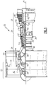
- FIG. 1 schematically illustrates an example gas turbine engine 20 that includes a fan section 22, a compressor section 24, a combustor section 26 and a turbine section 28.
- Alternative engines might include an augmenter section (not shown) among other systems or features.
- the fan section 22 drives air along a bypass flow path B while the compressor section 24 draws air in along a core flow path C where air is compressed and communicated to a combustor section 26.
- air is mixed with fuel and ignited to generate a high pressure exhaust gas stream that expands through the turbine section 28 where energy is extracted and utilized to drive the fan section 22 and the compressor section 24.
- a turbine engine including a three-spool architecture in which three spools concentrically rotate about a common axis and where a low spool enables a low pressure turbine to drive a fan via a gearbox, an intermediate spool that enables an intermediate pressure turbine to drive a first compressor of the compressor section, and a high spool that enables a high pressure turbine to drive a high pressure compressor of the compressor section.
- the example engine 20 generally includes a low speed spool 30 and a high speed spool 32 mounted for rotation about an engine central longitudinal axis A relative to an engine static structure 36 via several bearing systems 38. It should be understood that various bearing systems 38 at various locations may alternatively or additionally be provided.
- the low speed spool 30 generally includes an inner shaft 40 that connects a fan 42 and a low pressure (or first) compressor section 44 to a low pressure (or first) turbine section 46.
- the inner shaft 40 drives the fan 42 through a speed change device, such as a geared architecture 48, to drive the fan 42 at a lower speed than the low speed spool 30.
- the high-speed spool 32 includes an outer shaft 50 that interconnects a high pressure (or second) compressor section 52 and a high pressure (or second) turbine section 54.
- the inner shaft 40 and the outer shaft 50 are concentric and rotate via the bearing systems 38 about the engine central longitudinal axis A.
- a combustor 56 is arranged between the high pressure compressor 52 and the high pressure turbine 54.
- the high pressure turbine 54 includes at least two stages to provide a double stage high pressure turbine 54.
- the high pressure turbine 54 includes only a single stage.
- a "high pressure" compressor or turbine experiences a higher pressure than a corresponding "low pressure” compressor or turbine.
- the example low pressure turbine 46 has a pressure ratio that is greater than about 5.
- the pressure ratio of the example low pressure turbine 46 is measured prior to an inlet of the low pressure turbine 46 as related to the pressure measured at the outlet of the low pressure turbine 46 prior to an exhaust nozzle.
- a mid-turbine frame 58 of the engine static structure 36 is arranged generally between the high pressure turbine 54 and the low pressure turbine 46.
- the mid-turbine frame 58 further supports bearing systems 38 in the turbine section 28 as well as setting airflow entering the low pressure turbine 46.
- Airflow through the core airflow path C is compressed by the low pressure compressor 44 then by the high pressure compressor 52 mixed with fuel and ignited in the combustor 56 to produce high energy exhaust gases that are then expanded through the high pressure turbine 54 and low pressure turbine 46.
- the mid-turbine frame 58 includes vanes 60, which are in the core airflow path and function as an inlet guide vane for the low pressure turbine 46. Utilizing the vane 60 of the mid-turbine frame 58 as the inlet guide vane for low pressure turbine 46 decreases the length of the low pressure turbine 46 without increasing the axial length of the mid-turbine frame 58. Reducing or eliminating the number of vanes in the low pressure turbine 46 shortens the axial length of the turbine section 28. Thus, the compactness of the gas turbine engine 20 is increased and a higher power density may be achieved.
- the disclosed gas turbine engine 20 in one example is a high-bypass geared aircraft engine.
- the gas turbine engine 20 includes a bypass ratio greater than about six, with an example embodiment being greater than about ten.
- the example geared architecture 48 is an epicyclical gear train, such as a planetary gear system, star gear system or other known gear system, with a gear reduction ratio of greater than about 2.3.
- the gas turbine engine 20 includes a bypass ratio greater than about ten and the fan diameter is significantly larger than an outer diameter of the low pressure compressor 44. It should be understood, however, that the above parameters are only exemplary of one embodiment of a gas turbine engine including a geared architecture and that the present disclosure is applicable to other gas turbine engines.
- the fan section 22 of the engine 20 is designed for a particular flight condition -- typically cruise at about 0.8 Mach and about 35,000 feet (10,668 metres).
- the flight condition of 0.8 Mach and 35,000 ft. (10,668 m), with the engine at its best fuel consumption - also known as "bucket cruise Thrust Specific Fuel Consumption ('TSFC')" - is the industry standard parameter of pound-mass (lbm) of fuel per hour being burned divided by pound-force (lbf) of thrust the engine produces at that minimum point.
- Low fan pressure ratio is the pressure ratio across the fan blade alone, without a Fan Exit Guide Vane (“FEGV”) system.
- the low fan pressure ratio as disclosed herein according to one non-limiting embodiment is less than about 1.50. In another non-limiting embodiment the low fan pressure ratio is less than about 1.45.
- the "Low corrected fan tip speed”, as disclosed herein according to one non-limiting embodiment, is less than about 1150 ft/second (350.5 m/second).
- the example gas turbine engine includes the fan 42 that comprises in one non-limiting embodiment less than about twenty-six fan blades. In another non-limiting embodiment, the fan section 22 includes less than about twenty fan blades. Moreover, in one disclosed embodiment the low pressure turbine 46 includes no more than about six turbine rotors schematically indicated at 34. In another non-limiting example embodiment the low pressure turbine 46 includes about three turbine rotors. A ratio between the number of fan blades 42 and the number of low pressure turbine rotors is between about 3.3 and about 8.6. The example low pressure turbine 46 provides the driving power to rotate the fan section 22 and therefore the relationship between the number of turbine rotors 34 in the low pressure turbine 46 and the number of blades 42 in the fan section 22 disclose an example gas turbine engine 20 with increased power transfer efficiency.
- a blade outer air seal (BOAS) 62 defines a portion of the core flow path C for the high-energy exhaust gasses generated in the combustor 56.
- the BOAS 62 is disposed radially outward of a rotating airfoil 64.
- the BOAS 62 includes passages 70 that receive cooling air utilized to maintain the gas path surface at a temperature within material capabilities.
- the BOAS 62 includes a forward side 66 and an aft side 68.
- Each of the BOAS 62 are disposed within channels defined within a static structure 36 of the turbine engine 20.
- the BOAS 62 are supported within the static structure 36 and circumferentially surround rotatable airfoils 64 of the turbine section 28.
- each of the BOAS 62 includes the air passages 70 for cooling air flow.
- the passages 70 are formed using a sacrificial core schematically indicated at 72.
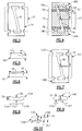
- Figure 3 illustrates the blade outer air seal 62 perimeter outline relative to the core 72.
- the core 72 is of a material that may be over molded with the metal alloy utilized to construct and form the BOAS 62 while being able to be removed once the BOAS 62 is completely formed. This disclosure contemplates use of the disclosed core 72 with any variation of known lost core molding processes.
- the core 72 defines empty spaces within the interior sections of a completed BOAS 62.
- open spaces in the core 72 define rigid and solid structures of the completed BOAS 62.
- the core 72 includes an open section 98 that is utilized to form a solid rib or wall portion within an interior space of the completed BOAS 62.
- the structure of the BOAS 62 is therefore dependent on the structure of the core 72 and both the completed BOAS 62 and the core 72 are within the contemplation of this disclosure.
- the core 72 defines air passages extending through the BOAS 62.
- Smaller airflow passages provide better thermal transfer as compared to larger airflow passages and therefore it is desirable to provide the core 72 with a small cross-sectional area to define smaller air flow passages through the BOAS 62.
- Smaller cross-sections may make certain core sections fragile and difficult to handle during manufacturing.
- thinner core sections 72 complicate manufacturing and can result in undesirable defects within the finished blade outer air seal 62.
- the example core 72 includes features that define air passages to improve thermal transfer while also improving manufacturability by tailoring cross-sectional areas and shapes in areas particularly susceptible to damage during manufacturing.
- an example core 72 that defines air passages through a BOAS 62 and includes an open section 98.
- the open section 98 defines a solid rib in the completed BOAS 62.
- the core 72 includes middle portion 82 between a first end portion 80A and a second end portion 80B.
- a transition portion 84 is disposed between the middle portion 82 and each of the end portions 80A and 80B.
- the end portions 80A, 80B, middle portion 82 and transition portions 84 refer to features in the core 72. Accordingly, the example core 72 includes a nonuniform shape from the first end portion 80a to the second end portion 80b.
- each of the airflow passages 70 ( Figure 2 ) includes end portions 74A, 74B, transition portions 78 and middle portions 76.
- the airflow passages 70 are continuous from one end portion 74A to the other end portion 74B.
- the core 72 defines the features of the passages 70 and include a first passage cross-section 86.
- the first passage cross section 86 defines the cross-section at the end portions 80B and 80A.
- the first passage cross-section 86 includes a first height 90 and a first width 96.
- a second passage cross-section 88 defines the core 72 within the middle portion 82.
- the second passage cross-section 88 includes a height 94 and a width 92.
- the first passage cross-section 86 and the second passage cross-section 88 refer to portions of the core 72 that define the completed passages and open areas.
- the core portion that defines the first passage cross-section 86 includes the first height 90 which is larger than the second height 94 of the second passage cross section 88.
- the first height 90 is two times greater than the second height 94.
- the first height 90 is no more than two times the second height 94. Accordingly, the end portions 80A and 80B include a larger core cross-section and thereby forms a larger completed air passage within end portions 74A, 74B in the completed BOAS 62.
- the transition area portion 84 of the core 72 includes a passage cross-section that transitions between the second cross section 88 of the middle portion 82 to the larger first cross-sections 86 at the end portions 80A and 80B.
- the variable height of the passages enable the use of thicker core sections in areas most susceptible to damage during manufacturing.
- the thinner second passage cross-section 88 defined by the core 72 in areas not as susceptible to damage during manufacture.
- the resulting air passage cross-section in the middle portion 76 of the completed BOAS 62 therefore benefits from the improved thermal transfer properties provided by the smaller cross-section.
- FIG. 7 another core assembly 102 is schematically illustrated for forming passages within a completed BOAS 100.
- the example BOAS 100 is shown schematically by the dashed line and includes passages that are formed by the core 102.
- the core 102 includes a uniform shape and configuration from a first end portion 130A to a second end portion 130B.
- the cross-section of the core 102 includes a unique shape that improves manufacturability while maintaining configurations desirable for air passages in a completed BOAS 100.
- the hot side also referred to as the flow path side of the passage wall of the BOAS 100 is the side that is down in the Figures.
- a first passage cross section 104 includes a middle section 112 between a first side section 110A and a second side section 110B.
- the middle section 112 includes a height 128 and the side sections 110A and 110B includes a height 126.
- the height 126 at each of the side sections 110A and 110B is greater than the height 128 of the middle sections.
- the end sections 110A and 110B define ribs that provide increased strength to that part of the core 102 during manufacture.
- the middle section 112 includes the smaller height 128 of the core 102 that is strengthened at the end sections 110A and 110B. Accordingly, the cross-section 104 of the core 102 can have ribs that provide strengthening features to enable more robust manufacturability while also maintaining the smaller cross sectional area in the middle section 112 that provides the desired thermal transfer properties in the completed BOAS 100.
- the ribs defined at the end sections 110A and 110B extend on a side that is not exposed to flow path side of the BOAS 100.
- the ribs of the end sections 110A and 110B extend from a side opposite the flow path or hot side of the BOAS and the side of the passage that is uniform or flat as shown in Figure 8 is on the flow path side.
- the height 126 is no more than two times the height 128 of the middle section 112. In another disclosed example embodiment, the height 126 is two times the height 128 of the middle section 112.
- another passage cross section 106 includes the middle section 112 with a height 114 and the side sections 110A and 110B with a height 116.
- the middle section 112 includes the greater height 114 while the end sections 110A and 110B include a reduced height.
- the height 114 of the middle section 112 in one example embodiment is no more than two times the height 116 of the end sections 110A and 110B. In another example embodiment the height of the middle section 112 is two times the height 116 at the end sections 110A and 110B.
- the center middle section 112 with the increased height 114 faces away from the hot side, or flow path side of the BOAS, and the side opposite is nearest the flow path side of the BOAS.
- another passage cross section 108 includes a middle section 118 with a height 124.
- Each end section 132A, 132B includes a height 120 that is smaller than the height 124.
- a transition region 122 is disposed between the middle section 118 and the end sections 132A, 132B such that a smooth transition from the height 124 to the height 120 is provided by the core 102.
- the height 124 is no more than two times the height 120 at the end sections 132A and 132B.
- the height 120 is two times the height 120 at the end sections 132A and 132B.
- the middle portion 118 increased height is provided in a direction away from the flow path side, such that the passage defines a uniform straight surface on the flow path side.
- variable cross sections of the example core provide improved strength and durability to improve and ease manufacturing while maintaining the desired thermal transfer properties for the completed BOAS.
- example core is disclosed by way of example for a BOAS, other structures that include passages formed using a core would benefit from this disclosure and are within the contemplation of this disclosure.
Landscapes
- Engineering & Computer Science (AREA)
- Mechanical Engineering (AREA)
- General Engineering & Computer Science (AREA)
- Chemical & Material Sciences (AREA)
- Combustion & Propulsion (AREA)
- Turbine Rotor Nozzle Sealing (AREA)
- Structures Of Non-Positive Displacement Pumps (AREA)
Applications Claiming Priority (1)
| Application Number | Priority Date | Filing Date | Title |
|---|---|---|---|
| US15/157,857 US11193386B2 (en) | 2016-05-18 | 2016-05-18 | Shaped cooling passages for turbine blade outer air seal |
Publications (2)
| Publication Number | Publication Date |
|---|---|
| EP3246533A1 true EP3246533A1 (de) | 2017-11-22 |
| EP3246533B1 EP3246533B1 (de) | 2023-06-28 |
Family
ID=58715137
Family Applications (1)
| Application Number | Title | Priority Date | Filing Date |
|---|---|---|---|
| EP17171827.3A Active EP3246533B1 (de) | 2016-05-18 | 2017-05-18 | Geformte kühlkanäle für aussendichtung für eine turbinenschaufel |
Country Status (2)
| Country | Link |
|---|---|
| US (1) | US11193386B2 (de) |
| EP (1) | EP3246533B1 (de) |
Cited By (1)
| Publication number | Priority date | Publication date | Assignee | Title |
|---|---|---|---|---|
| EP3533532A1 (de) * | 2018-03-01 | 2019-09-04 | Rolls-Royce plc | Kern für ein feingussverfahren |
Families Citing this family (1)
| Publication number | Priority date | Publication date | Assignee | Title |
|---|---|---|---|---|
| FR3080051B1 (fr) * | 2018-04-13 | 2022-04-08 | Safran | Noyau pour la fonderie d'une piece aeronautique |
Citations (4)
| Publication number | Priority date | Publication date | Assignee | Title |
|---|---|---|---|---|
| US5243759A (en) * | 1991-10-07 | 1993-09-14 | United Technologies Corporation | Method of casting to control the cooling air flow rate of the airfoil trailing edge |
| US20070248462A1 (en) * | 2005-09-30 | 2007-10-25 | United Technologies Corporation | Multiple cooling schemes for turbine blade outer air seal |
| EP1854567A2 (de) * | 2006-05-12 | 2007-11-14 | United Technologies Corporation | Profilierter metallener Gusskern |
| US8366383B2 (en) * | 2007-11-13 | 2013-02-05 | United Technologies Corporation | Air sealing element |
Family Cites Families (24)
| Publication number | Priority date | Publication date | Assignee | Title |
|---|---|---|---|---|
| US5326224A (en) * | 1991-03-01 | 1994-07-05 | General Electric Company | Cooling hole arrangements in jet engine components exposed to hot gas flow |
| US5649806A (en) | 1993-11-22 | 1997-07-22 | United Technologies Corporation | Enhanced film cooling slot for turbine blade outer air seals |
| KR960005230B1 (ko) | 1993-12-29 | 1996-04-23 | 포항종합제철주식회사 | 고강도 고인성 스프링용강의 제조방법 |
| FR2766517B1 (fr) * | 1997-07-24 | 1999-09-03 | Snecma | Dispositif de ventilation d'un anneau de turbomachine |
| US6139257A (en) * | 1998-03-23 | 2000-10-31 | General Electric Company | Shroud cooling assembly for gas turbine engine |
| US6984102B2 (en) | 2003-11-19 | 2006-01-10 | General Electric Company | Hot gas path component with mesh and turbulated cooling |
| GB0424593D0 (en) * | 2004-11-06 | 2004-12-08 | Rolls Royce Plc | A component having a film cooling arrangement |
| US7306424B2 (en) | 2004-12-29 | 2007-12-11 | United Technologies Corporation | Blade outer seal with micro axial flow cooling system |
| EP1990507B1 (de) | 2006-03-02 | 2015-04-15 | IHI Corporation | Prallkühlungsstruktur |
| US7686068B2 (en) | 2006-08-10 | 2010-03-30 | United Technologies Corporation | Blade outer air seal cores and manufacture methods |
| US7650926B2 (en) | 2006-09-28 | 2010-01-26 | United Technologies Corporation | Blade outer air seals, cores, and manufacture methods |
| US8439629B2 (en) * | 2007-03-01 | 2013-05-14 | United Technologies Corporation | Blade outer air seal |
| US7874792B2 (en) | 2007-10-01 | 2011-01-25 | United Technologies Corporation | Blade outer air seals, cores, and manufacture methods |
| US8061979B1 (en) | 2007-10-19 | 2011-11-22 | Florida Turbine Technologies, Inc. | Turbine BOAS with edge cooling |
| JP5412254B2 (ja) * | 2009-04-30 | 2014-02-12 | 三菱重工業株式会社 | タービン翼、タービン翼の製造方法、及び、ガスタービン |
| US8876458B2 (en) | 2011-01-25 | 2014-11-04 | United Technologies Corporation | Blade outer air seal assembly and support |
| US8596963B1 (en) * | 2011-07-07 | 2013-12-03 | Florida Turbine Technologies, Inc. | BOAS for a turbine |
| US8858159B2 (en) | 2011-10-28 | 2014-10-14 | United Technologies Corporation | Gas turbine engine component having wavy cooling channels with pedestals |
| US9279330B2 (en) * | 2012-02-15 | 2016-03-08 | United Technologies Corporation | Gas turbine engine component with converging/diverging cooling passage |
| US9103225B2 (en) | 2012-06-04 | 2015-08-11 | United Technologies Corporation | Blade outer air seal with cored passages |
| US20130340966A1 (en) | 2012-06-21 | 2013-12-26 | United Technologies Corporation | Blade outer air seal hybrid casting core |
| EP3084184B1 (de) | 2013-12-19 | 2022-03-23 | Raytheon Technologies Corporation | Kühlkanal für schaufelaussendichtung |
| US9713843B2 (en) * | 2014-01-22 | 2017-07-25 | United Technologies Corporation | Method for additively constructing internal channels |
| US10202864B2 (en) * | 2016-02-09 | 2019-02-12 | United Technologies Corporation | Chevron trip strip |
-
2016
- 2016-05-18 US US15/157,857 patent/US11193386B2/en active Active
-
2017
- 2017-05-18 EP EP17171827.3A patent/EP3246533B1/de active Active
Patent Citations (4)
| Publication number | Priority date | Publication date | Assignee | Title |
|---|---|---|---|---|
| US5243759A (en) * | 1991-10-07 | 1993-09-14 | United Technologies Corporation | Method of casting to control the cooling air flow rate of the airfoil trailing edge |
| US20070248462A1 (en) * | 2005-09-30 | 2007-10-25 | United Technologies Corporation | Multiple cooling schemes for turbine blade outer air seal |
| EP1854567A2 (de) * | 2006-05-12 | 2007-11-14 | United Technologies Corporation | Profilierter metallener Gusskern |
| US8366383B2 (en) * | 2007-11-13 | 2013-02-05 | United Technologies Corporation | Air sealing element |
Cited By (1)
| Publication number | Priority date | Publication date | Assignee | Title |
|---|---|---|---|---|
| EP3533532A1 (de) * | 2018-03-01 | 2019-09-04 | Rolls-Royce plc | Kern für ein feingussverfahren |
Also Published As
| Publication number | Publication date |
|---|---|
| EP3246533B1 (de) | 2023-06-28 |
| US20170335706A1 (en) | 2017-11-23 |
| US11193386B2 (en) | 2021-12-07 |
Similar Documents
| Publication | Publication Date | Title |
|---|---|---|
| EP3047119B1 (de) | Kühlkonfiguration für motorkomponenten | |
| USRE49382E1 (en) | High pressure rotor disk | |
| WO2015023338A2 (en) | Gas turbine engine component having trip strips | |
| EP3044418B1 (de) | Gasturbinenmotorschaufel mit gabelförmigem blechkühlsystem | |
| US11970954B2 (en) | Airfoil with rib having connector arms | |
| EP3078807B1 (de) | Kühlkanäle für eine gasturbinenmotorkomponente | |
| EP3255249A1 (de) | Gasturbinentriebwerkschaufel mit anstreifrippe | |
| US20190176228A1 (en) | Gas turbine engine component cooling passage and space eating core | |
| WO2014159800A1 (en) | Obtuse angle chevron trip strip | |
| EP3054094B1 (de) | Gasturbinenmotorturbinenschaufelablenkplatte und schlangenförmiger kühlkanal | |
| EP3650655B1 (de) | Schaufelprofil, zugehöriges gasturbinentriebwerk und montageverfahren | |
| EP4325026A1 (de) | Luftröhrenkühlkanal für tragflächenvorderkante | |
| EP2971544B1 (de) | Kühlung einer gasturbinenmotorkomponente mit verschachtelten, gegenüberliegenden nockenstreifen | |
| US20180252108A1 (en) | Staggered core printout | |
| EP3246533B1 (de) | Geformte kühlkanäle für aussendichtung für eine turbinenschaufel | |
| US11773726B2 (en) | Angled tip rods | |
| EP3693547B1 (de) | Gasturbinentriebwerksschaufel, gasturbinentriebwerk und verfahren zur herstellung einer gasturbinentriebwerksschaufel | |
| US11661850B2 (en) | Airfoil with convex sides and multi-piece baffle | |
| EP3246535B1 (de) | Turbinenleitschaufel mit versteifungsrippen für die deckbandschienen | |
| EP3061913B1 (de) | Gasturbinentriebwerksschaufel-kühlkonfiguration mit druckgefälleseparatoren |
Legal Events
| Date | Code | Title | Description |
|---|---|---|---|
| PUAI | Public reference made under article 153(3) epc to a published international application that has entered the european phase |
Free format text: ORIGINAL CODE: 0009012 |
|
| STAA | Information on the status of an ep patent application or granted ep patent |
Free format text: STATUS: THE APPLICATION HAS BEEN PUBLISHED |
|
| AK | Designated contracting states |
Kind code of ref document: A1 Designated state(s): AL AT BE BG CH CY CZ DE DK EE ES FI FR GB GR HR HU IE IS IT LI LT LU LV MC MK MT NL NO PL PT RO RS SE SI SK SM TR |
|
| AX | Request for extension of the european patent |
Extension state: BA ME |
|
| STAA | Information on the status of an ep patent application or granted ep patent |
Free format text: STATUS: REQUEST FOR EXAMINATION WAS MADE |
|
| 17P | Request for examination filed |
Effective date: 20180522 |
|
| RBV | Designated contracting states (corrected) |
Designated state(s): AL AT BE BG CH CY CZ DE DK EE ES FI FR GB GR HR HU IE IS IT LI LT LU LV MC MK MT NL NO PL PT RO RS SE SI SK SM TR |
|
| RAP1 | Party data changed (applicant data changed or rights of an application transferred) |
Owner name: RAYTHEON TECHNOLOGIES CORPORATION |
|
| STAA | Information on the status of an ep patent application or granted ep patent |
Free format text: STATUS: EXAMINATION IS IN PROGRESS |
|
| 17Q | First examination report despatched |
Effective date: 20210622 |
|
| GRAP | Despatch of communication of intention to grant a patent |
Free format text: ORIGINAL CODE: EPIDOSNIGR1 |
|
| STAA | Information on the status of an ep patent application or granted ep patent |
Free format text: STATUS: GRANT OF PATENT IS INTENDED |
|
| INTG | Intention to grant announced |
Effective date: 20230109 |
|
| RIN1 | Information on inventor provided before grant (corrected) |
Inventor name: RYAN, KEVIN J. Inventor name: LUTJEN, PAUL M. Inventor name: DAVIS, TIMOTHY M. |
|
| GRAS | Grant fee paid |
Free format text: ORIGINAL CODE: EPIDOSNIGR3 |
|
| GRAA | (expected) grant |
Free format text: ORIGINAL CODE: 0009210 |
|
| STAA | Information on the status of an ep patent application or granted ep patent |
Free format text: STATUS: THE PATENT HAS BEEN GRANTED |
|
| AK | Designated contracting states |
Kind code of ref document: B1 Designated state(s): AL AT BE BG CH CY CZ DE DK EE ES FI FR GB GR HR HU IE IS IT LI LT LU LV MC MK MT NL NO PL PT RO RS SE SI SK SM TR |
|
| REG | Reference to a national code |
Ref country code: CH Ref legal event code: EP |
|
| REG | Reference to a national code |
Ref country code: AT Ref legal event code: REF Ref document number: 1582859 Country of ref document: AT Kind code of ref document: T Effective date: 20230715 |
|
| REG | Reference to a national code |
Ref country code: IE Ref legal event code: FG4D |
|
| REG | Reference to a national code |
Ref country code: DE Ref legal event code: R096 Ref document number: 602017070601 Country of ref document: DE |
|
| REG | Reference to a national code |
Ref country code: LT Ref legal event code: MG9D |
|
| PG25 | Lapsed in a contracting state [announced via postgrant information from national office to epo] |
Ref country code: SE Free format text: LAPSE BECAUSE OF FAILURE TO SUBMIT A TRANSLATION OF THE DESCRIPTION OR TO PAY THE FEE WITHIN THE PRESCRIBED TIME-LIMIT Effective date: 20230628 Ref country code: NO Free format text: LAPSE BECAUSE OF FAILURE TO SUBMIT A TRANSLATION OF THE DESCRIPTION OR TO PAY THE FEE WITHIN THE PRESCRIBED TIME-LIMIT Effective date: 20230928 |
|
| RAP4 | Party data changed (patent owner data changed or rights of a patent transferred) |
Owner name: RTX CORPORATION |
|
| REG | Reference to a national code |
Ref country code: NL Ref legal event code: MP Effective date: 20230628 |
|
| REG | Reference to a national code |
Ref country code: AT Ref legal event code: MK05 Ref document number: 1582859 Country of ref document: AT Kind code of ref document: T Effective date: 20230628 |
|
| PG25 | Lapsed in a contracting state [announced via postgrant information from national office to epo] |
Ref country code: RS Free format text: LAPSE BECAUSE OF FAILURE TO SUBMIT A TRANSLATION OF THE DESCRIPTION OR TO PAY THE FEE WITHIN THE PRESCRIBED TIME-LIMIT Effective date: 20230628 Ref country code: NL Free format text: LAPSE BECAUSE OF FAILURE TO SUBMIT A TRANSLATION OF THE DESCRIPTION OR TO PAY THE FEE WITHIN THE PRESCRIBED TIME-LIMIT Effective date: 20230628 Ref country code: LV Free format text: LAPSE BECAUSE OF FAILURE TO SUBMIT A TRANSLATION OF THE DESCRIPTION OR TO PAY THE FEE WITHIN THE PRESCRIBED TIME-LIMIT Effective date: 20230628 Ref country code: LT Free format text: LAPSE BECAUSE OF FAILURE TO SUBMIT A TRANSLATION OF THE DESCRIPTION OR TO PAY THE FEE WITHIN THE PRESCRIBED TIME-LIMIT Effective date: 20230628 Ref country code: HR Free format text: LAPSE BECAUSE OF FAILURE TO SUBMIT A TRANSLATION OF THE DESCRIPTION OR TO PAY THE FEE WITHIN THE PRESCRIBED TIME-LIMIT Effective date: 20230628 Ref country code: GR Free format text: LAPSE BECAUSE OF FAILURE TO SUBMIT A TRANSLATION OF THE DESCRIPTION OR TO PAY THE FEE WITHIN THE PRESCRIBED TIME-LIMIT Effective date: 20230929 |
|
| PG25 | Lapsed in a contracting state [announced via postgrant information from national office to epo] |
Ref country code: FI Free format text: LAPSE BECAUSE OF FAILURE TO SUBMIT A TRANSLATION OF THE DESCRIPTION OR TO PAY THE FEE WITHIN THE PRESCRIBED TIME-LIMIT Effective date: 20230628 |
|
| PG25 | Lapsed in a contracting state [announced via postgrant information from national office to epo] |
Ref country code: SK Free format text: LAPSE BECAUSE OF FAILURE TO SUBMIT A TRANSLATION OF THE DESCRIPTION OR TO PAY THE FEE WITHIN THE PRESCRIBED TIME-LIMIT Effective date: 20230628 |
|
| PG25 | Lapsed in a contracting state [announced via postgrant information from national office to epo] |
Ref country code: ES Free format text: LAPSE BECAUSE OF FAILURE TO SUBMIT A TRANSLATION OF THE DESCRIPTION OR TO PAY THE FEE WITHIN THE PRESCRIBED TIME-LIMIT Effective date: 20230628 |
|
| PG25 | Lapsed in a contracting state [announced via postgrant information from national office to epo] |
Ref country code: IS Free format text: LAPSE BECAUSE OF FAILURE TO SUBMIT A TRANSLATION OF THE DESCRIPTION OR TO PAY THE FEE WITHIN THE PRESCRIBED TIME-LIMIT Effective date: 20231028 |
|
| PG25 | Lapsed in a contracting state [announced via postgrant information from national office to epo] |
Ref country code: SM Free format text: LAPSE BECAUSE OF FAILURE TO SUBMIT A TRANSLATION OF THE DESCRIPTION OR TO PAY THE FEE WITHIN THE PRESCRIBED TIME-LIMIT Effective date: 20230628 Ref country code: SK Free format text: LAPSE BECAUSE OF FAILURE TO SUBMIT A TRANSLATION OF THE DESCRIPTION OR TO PAY THE FEE WITHIN THE PRESCRIBED TIME-LIMIT Effective date: 20230628 Ref country code: RO Free format text: LAPSE BECAUSE OF FAILURE TO SUBMIT A TRANSLATION OF THE DESCRIPTION OR TO PAY THE FEE WITHIN THE PRESCRIBED TIME-LIMIT Effective date: 20230628 Ref country code: PT Free format text: LAPSE BECAUSE OF FAILURE TO SUBMIT A TRANSLATION OF THE DESCRIPTION OR TO PAY THE FEE WITHIN THE PRESCRIBED TIME-LIMIT Effective date: 20231030 Ref country code: IS Free format text: LAPSE BECAUSE OF FAILURE TO SUBMIT A TRANSLATION OF THE DESCRIPTION OR TO PAY THE FEE WITHIN THE PRESCRIBED TIME-LIMIT Effective date: 20231028 Ref country code: ES Free format text: LAPSE BECAUSE OF FAILURE TO SUBMIT A TRANSLATION OF THE DESCRIPTION OR TO PAY THE FEE WITHIN THE PRESCRIBED TIME-LIMIT Effective date: 20230628 Ref country code: EE Free format text: LAPSE BECAUSE OF FAILURE TO SUBMIT A TRANSLATION OF THE DESCRIPTION OR TO PAY THE FEE WITHIN THE PRESCRIBED TIME-LIMIT Effective date: 20230628 Ref country code: CZ Free format text: LAPSE BECAUSE OF FAILURE TO SUBMIT A TRANSLATION OF THE DESCRIPTION OR TO PAY THE FEE WITHIN THE PRESCRIBED TIME-LIMIT Effective date: 20230628 Ref country code: AT Free format text: LAPSE BECAUSE OF FAILURE TO SUBMIT A TRANSLATION OF THE DESCRIPTION OR TO PAY THE FEE WITHIN THE PRESCRIBED TIME-LIMIT Effective date: 20230628 |
|
| PG25 | Lapsed in a contracting state [announced via postgrant information from national office to epo] |
Ref country code: PL Free format text: LAPSE BECAUSE OF FAILURE TO SUBMIT A TRANSLATION OF THE DESCRIPTION OR TO PAY THE FEE WITHIN THE PRESCRIBED TIME-LIMIT Effective date: 20230628 |
|
| REG | Reference to a national code |
Ref country code: DE Ref legal event code: R097 Ref document number: 602017070601 Country of ref document: DE |
|
| PG25 | Lapsed in a contracting state [announced via postgrant information from national office to epo] |
Ref country code: DK Free format text: LAPSE BECAUSE OF FAILURE TO SUBMIT A TRANSLATION OF THE DESCRIPTION OR TO PAY THE FEE WITHIN THE PRESCRIBED TIME-LIMIT Effective date: 20230628 |
|
| PLBE | No opposition filed within time limit |
Free format text: ORIGINAL CODE: 0009261 |
|
| STAA | Information on the status of an ep patent application or granted ep patent |
Free format text: STATUS: NO OPPOSITION FILED WITHIN TIME LIMIT |
|
| PG25 | Lapsed in a contracting state [announced via postgrant information from national office to epo] |
Ref country code: IT Free format text: LAPSE BECAUSE OF FAILURE TO SUBMIT A TRANSLATION OF THE DESCRIPTION OR TO PAY THE FEE WITHIN THE PRESCRIBED TIME-LIMIT Effective date: 20230628 |
|
| 26N | No opposition filed |
Effective date: 20240402 |
|
| PG25 | Lapsed in a contracting state [announced via postgrant information from national office to epo] |
Ref country code: SI Free format text: LAPSE BECAUSE OF FAILURE TO SUBMIT A TRANSLATION OF THE DESCRIPTION OR TO PAY THE FEE WITHIN THE PRESCRIBED TIME-LIMIT Effective date: 20230628 |
|
| PG25 | Lapsed in a contracting state [announced via postgrant information from national office to epo] |
Ref country code: BG Free format text: LAPSE BECAUSE OF FAILURE TO SUBMIT A TRANSLATION OF THE DESCRIPTION OR TO PAY THE FEE WITHIN THE PRESCRIBED TIME-LIMIT Effective date: 20230628 |
|
| PG25 | Lapsed in a contracting state [announced via postgrant information from national office to epo] |
Ref country code: BG Free format text: LAPSE BECAUSE OF FAILURE TO SUBMIT A TRANSLATION OF THE DESCRIPTION OR TO PAY THE FEE WITHIN THE PRESCRIBED TIME-LIMIT Effective date: 20230628 |
|
| REG | Reference to a national code |
Ref country code: CH Ref legal event code: PL |
|
| PG25 | Lapsed in a contracting state [announced via postgrant information from national office to epo] |
Ref country code: MC Free format text: LAPSE BECAUSE OF FAILURE TO SUBMIT A TRANSLATION OF THE DESCRIPTION OR TO PAY THE FEE WITHIN THE PRESCRIBED TIME-LIMIT Effective date: 20230628 |
|
| PG25 | Lapsed in a contracting state [announced via postgrant information from national office to epo] |
Ref country code: LU Free format text: LAPSE BECAUSE OF NON-PAYMENT OF DUE FEES Effective date: 20240518 |
|
| PG25 | Lapsed in a contracting state [announced via postgrant information from national office to epo] |
Ref country code: MC Free format text: LAPSE BECAUSE OF FAILURE TO SUBMIT A TRANSLATION OF THE DESCRIPTION OR TO PAY THE FEE WITHIN THE PRESCRIBED TIME-LIMIT Effective date: 20230628 Ref country code: LU Free format text: LAPSE BECAUSE OF NON-PAYMENT OF DUE FEES Effective date: 20240518 Ref country code: CH Free format text: LAPSE BECAUSE OF NON-PAYMENT OF DUE FEES Effective date: 20240531 |
|
| REG | Reference to a national code |
Ref country code: BE Ref legal event code: MM Effective date: 20240531 |
|
| PG25 | Lapsed in a contracting state [announced via postgrant information from national office to epo] |
Ref country code: IE Free format text: LAPSE BECAUSE OF NON-PAYMENT OF DUE FEES Effective date: 20240518 |
|
| PG25 | Lapsed in a contracting state [announced via postgrant information from national office to epo] |
Ref country code: BE Free format text: LAPSE BECAUSE OF NON-PAYMENT OF DUE FEES Effective date: 20240531 |
|
| PGFP | Annual fee paid to national office [announced via postgrant information from national office to epo] |
Ref country code: DE Payment date: 20250423 Year of fee payment: 9 |
|
| PGFP | Annual fee paid to national office [announced via postgrant information from national office to epo] |
Ref country code: GB Payment date: 20250423 Year of fee payment: 9 |
|
| PGFP | Annual fee paid to national office [announced via postgrant information from national office to epo] |
Ref country code: FR Payment date: 20250423 Year of fee payment: 9 |
|
| PG25 | Lapsed in a contracting state [announced via postgrant information from national office to epo] |
Ref country code: CY Free format text: LAPSE BECAUSE OF FAILURE TO SUBMIT A TRANSLATION OF THE DESCRIPTION OR TO PAY THE FEE WITHIN THE PRESCRIBED TIME-LIMIT; INVALID AB INITIO Effective date: 20170518 |
|
| PG25 | Lapsed in a contracting state [announced via postgrant information from national office to epo] |
Ref country code: HU Free format text: LAPSE BECAUSE OF FAILURE TO SUBMIT A TRANSLATION OF THE DESCRIPTION OR TO PAY THE FEE WITHIN THE PRESCRIBED TIME-LIMIT; INVALID AB INITIO Effective date: 20170518 |
|
| REG | Reference to a national code |
Ref country code: DE Ref legal event code: R081 Ref document number: 602017070601 Country of ref document: DE Owner name: RTX CORPORATION (N.D.GES.D. STAATES DELAWARE),, US Free format text: FORMER OWNER: RAYTHEON TECHNOLOGIES CORPORATION, FARMINGTON, CT, US |
|
| P01 | Opt-out of the competence of the unified patent court (upc) registered |
Free format text: CASE NUMBER: UPC_APP_0019310_3246533/2025 Effective date: 20251223 |