EP1854630A2 - Dispositif de revêtement ou de flocage des objects, notamment des materiaux textils avec pochoir - Google Patents
Dispositif de revêtement ou de flocage des objects, notamment des materiaux textils avec pochoir Download PDFInfo
- Publication number
- EP1854630A2 EP1854630A2 EP07009042A EP07009042A EP1854630A2 EP 1854630 A2 EP1854630 A2 EP 1854630A2 EP 07009042 A EP07009042 A EP 07009042A EP 07009042 A EP07009042 A EP 07009042A EP 1854630 A2 EP1854630 A2 EP 1854630A2
- Authority
- EP
- European Patent Office
- Prior art keywords
- flocking
- template frame
- container
- coating
- fixing elements
- Prior art date
- Legal status (The legal status is an assumption and is not a legal conclusion. Google has not performed a legal analysis and makes no representation as to the accuracy of the status listed.)
- Withdrawn
Links
Images


Classifications
-
- B—PERFORMING OPERATIONS; TRANSPORTING
- B41—PRINTING; LINING MACHINES; TYPEWRITERS; STAMPS
- B41F—PRINTING MACHINES OR PRESSES
- B41F15/00—Screen printers
- B41F15/08—Machines
- B41F15/0863—Machines with a plurality of flat screens mounted on a turntable
-
- B—PERFORMING OPERATIONS; TRANSPORTING
- B41—PRINTING; LINING MACHINES; TYPEWRITERS; STAMPS
- B41F—PRINTING MACHINES OR PRESSES
- B41F15/00—Screen printers
- B41F15/14—Details
- B41F15/34—Screens, Frames; Holders therefor
- B41F15/36—Screens, Frames; Holders therefor flat
-
- B—PERFORMING OPERATIONS; TRANSPORTING
- B41—PRINTING; LINING MACHINES; TYPEWRITERS; STAMPS
- B41P—INDEXING SCHEME RELATING TO PRINTING, LINING MACHINES, TYPEWRITERS, AND TO STAMPS
- B41P2215/00—Screen printing machines
- B41P2215/10—Screen printing machines characterised by their constructional features
- B41P2215/11—Registering devices
- B41P2215/112—Registering devices with means for displacing the frame
Definitions
- the invention relates to a device for coating or flocking articles, in particular of textile materials, mats, ceramics, plastic, paper, wood, metal or the like, as well as a flocking machine.
- the flock material used is preferably short fibers, in particular textile fibers.
- electrostatic charging of fibers received in a container the flock material is applied to the article to be flocked.
- a Beflockungsvorraum which consists of several printing units, which are each assigned to a arranged on a pallet carrier pallet.
- the pallet carriers are provided on a rotary drive which transports the object arranged on the pallet from processing station to processing station.
- a flocking container is provided, which applies the textile fibers to the object in the processing station.
- the invention is therefore an object of the invention to provide a device for coating or flocking articles, especially textile materials and a flocking machine, which allows a quick and accurate adjustment of a print motif to the palette, which receives the object to be flocked, as well as a reduction of Pollution by not applied flocked material allows.
- a quick and easy setting of a stencil frame with a print motif is made possible to fixing elements, which are assigned to a container receiving the flock material.
- These fixing elements simultaneously serve to receive and position a pallet to the template frame, which receives the object to be coated or flocked, so that an exact positioning of the pallet and thus of the object to be coated is made possible for the aligned template frame.
- the template frame takes over a grid or one Fabric the print motif.
- the area to be coated or flocked on the article is continuous to the fabric or grid for the flock material and the non-coated area of the article is formed on the grid or fabric as a closed surface.
- An aligning device which can be attached to the fixing elements allows the template frame to be aligned precisely with the fixing elements in a simple and fast manner.
- the print motif is thereby applied to the object to be coated with high accuracy, since the pallet carrying the object to be coated or flocked is likewise aligned by the fixing elements to the template frame.
- Flocking from below takes place through the template frame arranged on the upper end of the container and the pallet resting thereon, that is to say that the flock material located in the container interior is applied by the electrostatic charge from bottom to top onto the object provided with an adhesive layer.
- the arrangement according to the invention has both the advantage that a simple fixation and alignment of the template frame is given as well as a significantly pollution-minimized flocking is possible.
- the setting device for the template frame comprises a bearing surface on which the template frame rests at least in sections and preferably the fixing elements are positioned in the bearing surface of the adjusting device.
- the bearing surface of the adjusting device is preferably fixed to the container.
- the support surface of the adjustment device is adjacent to the outer wall of the container and surrounding it.
- the fixing elements are preferably designed to be higher than the template frame resting on the support surface. Both the alignment device and the pallet can thus rest directly on the template frame. When placing the alignment device can be made an aligning engagement with the template frame. When placing a pallet, a seal of flocking space may be given, so that the pollution is reduced.
- the fixing pins represent the simplest embodiment as fixing elements. It is understood that other elements can be provided for a snug fit and quick release arrangement.
- the bearing surface of the adjusting device preferably has adjusting elements which are arranged on the support surface via holders in order to engage or engage the template frame and to position it in its position relative to the fixing elements.
- These adjusting elements can be provided according to an embodiment as adjusting screws with a thread or fine thread, which are manually operated.
- infinitely adjustable positioning elements for example via a clamping, can be provided in order to allow alignment of the template frame in the X and Y directions or in an alignment plane.
- the alignment device for positioning and adjusting the template frame is preferably formed of a transparent material.
- a simple optical alignment of the template frame to the alignment device can take place via indexing or setting markings.
- a plastic is provided as the transparent material, such as Plexiglas.
- the alignment device advantageously has a small wall thickness. The wall thickness is less than 10 mm, in particular less than 5 mm thick, designed to avoid so-called paralax error when aligning the indexing or Einstellmark isten.
- the alignment device advantageously has at one end face a bore and at an opposite end side two spaced-apart U- or V-shaped, adjacent to the end face Recesses, which preferably have an insertion bevel. These recesses and holes are adapted in dimensions to the arranged on the support surface fixing pins. First, the open-edged recesses of the alignment aid or alignment device are positioned to the fixing elements. Subsequently, the opposite fixing pin is caught by the hole. Thus, a positioning of the alignment is possible in a simple and fast way. The same applies to a pallet receiving the coating article, which preferably comprises the same structure, in particular in the case of a manual flocking station.
- the bearing surface of the adjusting device is provided on an outer container wall and preferably recessed relative to an upper container edge. This allows the template frame encompass and cover this free upper container edge. Due to the support of the template frame on the support surface and / or the grid or tissue on the upper edge of the container, the interior of the flocking container is closed, so that the risk of contamination is reduced.
- the support surface is preferably variable in height adjustable to the container and possibly also interchangeable, so that a simple and quick adaptation to different template frame is possible.
- the alignment device has at least two setting marks, which are preferably arranged with a large distance from each other. These alignment marks indicate the exact location of the subject to be flocked on the pallet. On the template frame also at least two markings are provided which have a defined distance from the print motif, so that an adjustment of the template frame is given by the congruent orientation of the markers.
- the object to be flocked is applied or applied to a pallet, which is coated with an adhesive in the region of the motif to be applied and then positioned with the side to be flocked to the container interior becomes.
- the pallet In a manual flocking station, the pallet is usually referred to as a pallet mask, which receives the object to be flocked.
- an adhesive layer is sprayed on first, so that the textile, for example, with a smooth surface rests on the pallet. Due to the orientation of the pallet over the fixing elements, the region provided with adhesive is arranged on the object congruent to the permeable region of the grid or fabric for the flock material.
- the device according to the invention for coating or flocking articles in particular textile materials, mats, ceramics, plastics, wood, metal, paper or the like, can be used both as a manual station and in an automatic flocking machine comprising a plurality of printing units.
- Flock materials with different flock length and / or type of flock material and / or color may be provided in the individual printing units.
- the flocking containers are stationarily associated with a flocking machine, wherein the pallets are transported intermittently from Beflockungsbereheat to flocking via a rotary drive.
- the template frame can be moved up and down, wherein between the template frame and the flock receiving container receiving a variable-length sleeve, sleeve or the like is provided to allow a closed arrangement
- the flocking can be provided movable relative to the pallets.
- Such an automatic flocking machine can be designed as a rotary transfer machine or as a longitudinal transfer machine. The number of stations of the flocking machine is essentially determined by the number of printing units.
- FIG. 1 shows a schematic side view of the device 11 according to the invention for flocking an article, in particular for a manual flocking station for flocking, for example, textile articles.
- the objects to be stained can be made of natural or artificial materials. By flocking a refining of the product. These may be, for example, clothing items or floor mats for indoor and outdoor use or for vehicles or decorative items.
- FIG. 2 shows a schematic sectional view of the device 11 according to FIG. 1, and FIG. 3 shows a plan view of the device according to the invention Device 11 shown, to which reference is made below.
- the device 11 comprises a container 12 in which a flock material 13 is provided.
- a flock material 13 is provided.
- short fibers in particular natural or artificial textile fibers, are preferably used to perform the flocking.
- the container 12 comprises at the bottom an electrode 14, which is responsible for the electrostatic charging of the fibers, at the upper end of the container 12, an adjusting device 16 is provided, which according to the embodiment comprises a support surface 17 which connects to outer walls 18 of the container 12 and is recessed relative to an upper container rim 21. Alternatively it can be provided that the support surface 17 rests against the upper container rim 21 or forms part of the upper container opening.
- the adjusting device 16 can be provided replaceably to a standard container size 12, so that differently sized Häblonenrahmen 23 can be used.
- the illustrated template frame 23 is larger than the container 12 is formed and surrounds this.
- An end face 24 of the template frame 23 is at least partially on the support surface 17 of the adjusting device 16.
- the template frame 23 carries a grid or fabric 26 on which a print motif 27 is applied.
- This print motif 27 may be applied by various techniques wherein the areas of an article to be flocked are formed in the motif 27 as permeable areas and the areas not to be flocked are provided as impermeable areas.
- the template frame 23 is formed, for example, as a rectangular frame by tubular profiles, to which the grid or fabric 26 is mounted interchangeable.
- clamping elements may be provided on the template frame to allow the application of a clamping force on the tissue for tight recording.
- the zero potential is connected, so that in the container interior, a directional high voltage field to the template frame 23 is applied to perform the flocking.
- the adjusting device 16 has at the support surface 17 brackets 31, which are formed for example as a corner angle. These holders 31 receive adjustment elements 32 in order to align the template frame 23 in the X and Y direction or in the support plane of the support surface 17.
- the adjusting elements 32 include, for example threaded rods that are manually adjustable. Alternatively, spring-loaded pins can be provided which are infinitely adjustable by a clamping element. In a further embodiment, not shown, it can be provided that the adjusting elements 32 are driven by a motor in order to allow the alignment of the template frame 23. In the plan view according to FIG. 4, for example, five adjusting elements 32 are provided. The number and arrangement is dependent on the configuration of the adjusting elements 32, but at least such a number of adjusting elements 32 is provided so that a precise adjustment and alignment of the template frame 23 in the X / Y plane is possible.
- the adjusting device 16 has fixing elements 34, in particular fixing pins or fixing bolts, which are fixedly arranged in the support surface 17. These fixing elements 34 serve to receive a pallet on which the object to be coated or to be flocked is applied.
- an alignment device 38 according to FIG. 4 is provided.
- This alignment device 38 has, for example, a bore 41 lying in the plane of symmetry on an end face 42 and on an opposite end face 43 two open-edged U-shaped recesses 44 which are spaced apart from one another. These recesses 44 may also have V-shaped or other geometries that allow a centering of the alignment device 38 to the fixing elements 34.
- insertion chamfers 46 are preferably provided. Such an insertion bevel 46 may also be provided on the bore 41 in the form of a countersink.
- the alignment device 38 is positioned on the fixing elements 34.
- On the alignment device 38 are at least two setting marks 48 provided. These adjustment marks 48 are preferably applied to the same side, which is brought directly to the tissue 26 for conditioning.
- the alignment device 38 is transparent at least in the region of the alignment marks 48, preferably formed completely transparent, and has a thin plate thickness to avoid parallax errors in the alignment of the template frame 23.
- On the fabric 26 are also relative to the print motif 27 setting marks 48 are provided.
- the alignment device 38 is preferably located directly on the template frame 23 in analogy to the pallet, as is done in a flocking or coating process.
- the fixing elements 34 are designed in their length such that they protrude slightly at least relative to the template frame 23, in order to allow alignment of the alignment device 38.
- three fixing elements 34 are provided in order to achieve a statically determined recording of the alignment device 38.
- the arrangement of the fixing elements 34 to each other is only an example, wherein the arrangement of two fixing elements 34 along a side edge of the template frame 23 has the advantage that a slight positioning of the alignment device 38 and the pallet on the edge open U-shaped recesses 44 is possible.
- the fixing elements 34 are arranged on the container 12.
- Their length can be variable according to a further preferred embodiment, for example, to allow adjustment of different thickness template frame 23. This variability in the length of the fixing elements 34 can be achieved by replacing the fixing elements 34 or by an adjustability in analogy to the adjusting elements 32nd
- the template frame 23 is fixed in a preferred embodiment simultaneously to the support surface 17, so that a quasi-tight conclusion is given. As a result, the risk of contamination is considerably minimized.
- a pallet 36 has a geometry at a manual flocking station which substantially corresponds to the alignment device 38 in FIG. Only the setting marks 48 are not required here.
- the object to be coated is placed, slipped over or held by a releasable adhesive bond, so that it rests on the fabric 26 of the template frame 23 during coating or flocking and aligned via the bore 41 and recesses 44 to the print motif 27 of the template frame 23 is.
- spacer elements are applied to the fabric 26 adjacent to the motif to maintain a defined distance between the fabric 26 and the pallet 36.
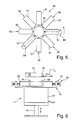
- FIGS. 5 and 6 show a flocking machine 49 as a rotary transfer machine, which comprises at least one flocking station 56 with the device 11 according to the invention.
- a flocking machine 49 has a basic construction substantially similar to that according to FIGS DE 196 22 230 A1 equivalent.
- Via a rotary drive 50 several pallets, which are connected to the flocking machine 49 with pallet carriers 51, transported from one processing station to the next to make a flocking.
- a processing station 52 for example, the surface of a pallet 36 is provided with a spray adhesive.
- the object to be coated is applied to the pallet 36. This can be, for example, a textile material.
- a processing station 54 the pallet carrier 51 is rotated by 180 ° so that the top of the article to be flocked points downwards.
- a first flocking station 56 which is shown in a side view in FIG. 6, flocking with a flock material takes place.
- the device 11 is moved via a lifting cylinder 61 upwards, so that the pallet carrier 51 is positioned over the fixing elements 34 to the template frame 23 and the pallet comes to rest on the template frame 23.
- the flocking is performed by applying a high voltage field.
- the device 11 is moved over the lifting cylinder 61 and other height-adjustable mechanisms lowered, and the rotary actuator 50 clocks the pallet carrier 51 in an emptying station or a subsequent flocking station 57 on.
- This may include deviant flock material in the color, type and / or size of the fibers.
- a rotation of the pallet carrier 51 by 180 °, so that the object to be coated is provided for removal in a processing station 59.
- a flocking machine may be designed as a longitudinal transfer machine.
- the stations described in FIG. 5 can be provided in a line one behind the other.
- a linear axis drive is provided which, for example, successively leads or continues the clockwise movement of the charge carrier to the individual processing stations.
- the pallet carrier can be arranged stationary, wherein the individual processing stations are moved back and forth below the pallet carrier, so that the respective processing step is performed.
- the pallet carrier is provided on a rotary drive, so that, for example, a series of flocking stations opposite to a loading and unloading station is provided to provide the pallet with a spray adhesive and an object to be coated, in which case the Pallet is rotated 180 ° in the horizontal in a processing station. In this processing position, several flocking stations can be sequentially assigned to the pallet carrier. At the same time, another pallet carrier for a new flocking task can be prepared in the loading and unloading station.
- the variations and embodiments described with reference to FIGS. 5 and 6 apply analogously to a flocking machine designed as a linear transfer machine.
- a drying station in particular after the last flocking process, may be provided.
- the number of pallet carrier 51 in the flocking machine 49 is arbitrary.
- One or more flocking stations 56, 57 may be provided.
- an adhesive application station can also be used and / or an inking station and / or a printing unit are integrated.
- the device 11 according to the invention allows both manual and mechanical use with reduced setting times for the template frame 23 and at the same time reducing the risk of fouling by the use of flocking from below.
- the device 11 according to the invention can also be used for the alignment and adjustment of a template frame 23, which is provided for applying an adhesive layer to an object, in order subsequently to apply the print motif 27. Furthermore, the device 11 according to the invention can also be provided for use in a liquid or pasty medium which requires an exact alignment of a motif 27.
Landscapes
- Engineering & Computer Science (AREA)
- Mechanical Engineering (AREA)
- Application Of Or Painting With Fluid Materials (AREA)
- Coating Apparatus (AREA)
- Treatment Of Fiber Materials (AREA)
Applications Claiming Priority (1)
| Application Number | Priority Date | Filing Date | Title |
|---|---|---|---|
| DE102006021799A DE102006021799B3 (de) | 2006-05-09 | 2006-05-09 | Vorrichtung zum Beschichten oder Beflocken von Gegenständen, insbesondere von textilen Werkstoffen, sowie Beflockungsmaschine |
Publications (2)
| Publication Number | Publication Date |
|---|---|
| EP1854630A2 true EP1854630A2 (fr) | 2007-11-14 |
| EP1854630A3 EP1854630A3 (fr) | 2010-06-02 |
Family
ID=38171362
Family Applications (1)
| Application Number | Title | Priority Date | Filing Date |
|---|---|---|---|
| EP07009042A Withdrawn EP1854630A3 (fr) | 2006-05-09 | 2007-05-04 | Dispositif de revêtement ou de flocage des objects, notamment des materiaux textils avec pochoir |
Country Status (3)
| Country | Link |
|---|---|
| US (1) | US7854196B2 (fr) |
| EP (1) | EP1854630A3 (fr) |
| DE (1) | DE102006021799B3 (fr) |
Cited By (1)
| Publication number | Priority date | Publication date | Assignee | Title |
|---|---|---|---|---|
| USD938648S1 (en) * | 2020-08-10 | 2021-12-14 | Louisa Anthony Hair Goods Inc. | Hair flocking device |
Families Citing this family (3)
| Publication number | Priority date | Publication date | Assignee | Title |
|---|---|---|---|---|
| CN101537407B (zh) * | 2008-11-14 | 2012-05-30 | 厦门创薪设备科技有限公司 | 一种改进型的植绒机 |
| US9144285B2 (en) | 2012-08-27 | 2015-09-29 | Goody Products, Inc. | Hair accessories and methods for their manufacture |
| CN107855253A (zh) * | 2017-12-08 | 2018-03-30 | 张家港炬弘板业有限公司 | 便捷式钢卷涂粉装置 |
Family Cites Families (17)
| Publication number | Priority date | Publication date | Assignee | Title |
|---|---|---|---|---|
| US3404624A (en) * | 1964-06-01 | 1968-10-08 | Owens Illinois Inc | Offset plate decorating methods and apparatus |
| US3390756A (en) * | 1965-08-25 | 1968-07-02 | Monsanto Co | Geneva type actuating mechanism |
| US3589283A (en) * | 1969-02-19 | 1971-06-29 | Electrostatic Printing Corp | Multicolor electrostatic printing system |
| US3793050A (en) * | 1971-08-12 | 1974-02-19 | E Mumpower | Method of applying flocking to a base |
| DE2745619A1 (de) * | 1977-10-05 | 1979-04-19 | Champion Products | Beflockungsverfahren und -einrichtungen |
| US4463673A (en) * | 1981-09-08 | 1984-08-07 | Michael Moore | Method and apparatus for registration of planar members and the like through the employment of an intermediate alignment sheet |
| US4939991A (en) * | 1987-11-06 | 1990-07-10 | Precision Screen Machines, Inc. | Multicolor screen printing assembly |
| US5185040A (en) * | 1988-12-19 | 1993-02-09 | Murata Manufacturing Co., Ltd. | Apparatus for forming electrode on electronic component |
| DE3934929A1 (de) * | 1989-10-20 | 1991-04-25 | Rudolf August Kuerten | Passer-system fuer den siebdruck |
| US5076162A (en) * | 1990-10-04 | 1991-12-31 | Goin Bobby G | Expandable mesh frame |
| JPH0596700A (ja) * | 1991-10-04 | 1993-04-20 | Murata Mfg Co Ltd | スクリーン印刷の位置合わせ方法 |
| DE19622230A1 (de) * | 1996-06-03 | 1997-12-04 | Schenk Gmbh | Vorrichtung zum Bedrucken von Materialien, insbesondere textilen Werkstoffen, Keramik, Papier oder dergleichen |
| JPH10129098A (ja) * | 1996-10-30 | 1998-05-19 | Riso Kagaku Corp | 減圧式孔版印刷方法及び装置 |
| US6575091B2 (en) * | 1998-08-06 | 2003-06-10 | Reefdale Proprietary Limited | Screen printing machines |
| US6234077B1 (en) * | 1999-02-26 | 2001-05-22 | Micron Technology, Inc. | Method and apparatus for screen printing |
| US6338297B1 (en) * | 2000-05-26 | 2002-01-15 | Industrial Technology Research Institute | Precise and rapid positioning mechanism for stencil printing |
| CN100439101C (zh) * | 2004-06-01 | 2008-12-03 | 东远精技工业股份有限公司 | 悬臂式双台面网印机 |
-
2006
- 2006-05-09 DE DE102006021799A patent/DE102006021799B3/de not_active Expired - Fee Related
-
2007
- 2007-05-04 EP EP07009042A patent/EP1854630A3/fr not_active Withdrawn
- 2007-05-09 US US11/801,343 patent/US7854196B2/en not_active Expired - Fee Related
Cited By (1)
| Publication number | Priority date | Publication date | Assignee | Title |
|---|---|---|---|---|
| USD938648S1 (en) * | 2020-08-10 | 2021-12-14 | Louisa Anthony Hair Goods Inc. | Hair flocking device |
Also Published As
| Publication number | Publication date |
|---|---|
| EP1854630A3 (fr) | 2010-06-02 |
| US20070272101A1 (en) | 2007-11-29 |
| US7854196B2 (en) | 2010-12-21 |
| DE102006021799B3 (de) | 2007-11-15 |
Similar Documents
| Publication | Publication Date | Title |
|---|---|---|
| EP2830828B1 (fr) | Procédé pour le meulage en plusieurs étapes de pièces | |
| EP3197639B1 (fr) | Dispositif d'usinage | |
| EP3482939B1 (fr) | Système de mise à disposition d'ecran | |
| AT13360U1 (de) | Vorrichtung und Verfahren zum Auftragen von Farbe auf einen plattenförmigen Gegenstand | |
| DE102007050953A1 (de) | Vorrichtung zum schichtweisen Aufbau von Modellen | |
| DE202014011375U1 (de) | Anlage zur Herstellung von dreidimensionalen Siebdrucken | |
| DE1923833A1 (de) | Vorrichtung zur Befestigung von Werkstuecken od.dgl. an einer Werkzeugmaschine | |
| DE10022269A1 (de) | Verfahren und Vorrichtung zur Durchführung eines Produktwechsels bei Thermoformvorgängen | |
| WO2020127536A1 (fr) | Procédé et dispositif pour l'estampage de plaques d'immatriculation, en particulier de plaques d'immatriculation de véhicule automobile | |
| WO2018019818A1 (fr) | Table d'avance | |
| WO2009016250A1 (fr) | Dispositif porte-outil et dispositif pour usiner des pièces découpées plates | |
| EP1854630A2 (fr) | Dispositif de revêtement ou de flocage des objects, notamment des materiaux textils avec pochoir | |
| EP0046474B1 (fr) | Procédé et dispositif pour imprimer des objets en forme de caisse avec des pochoirs disposés verticalement | |
| DE102024118524A1 (de) | Aufnahmevorrichtung für pharmazeutische Behälter, planares Transportsystem und Anlage zum Verarbeiten pharmazeutischer Behälter | |
| DE19614740A1 (de) | Verfahren und Vorrichtung zum Bedrucken von selbsttragenden Einzelobjekten | |
| EP3482935B1 (fr) | Unité de tamisage pour un dispositif d'impression | |
| DE202010002623U1 (de) | Platteneinzugsvorrichtung | |
| AT15693U1 (de) | Ausrichten eines plattenförmigen gegenstands | |
| DE102019110567A1 (de) | Haftmittelauftragseinrichtung | |
| EP0584542A1 (fr) | Méthode et dispositif pour imprimer des objets | |
| EP0446397A1 (fr) | Dispositif de présentation d'étiquettes au point de couture pour machine à coudre industrielle | |
| DE19500400C2 (de) | Auflagersystem für mit Kunststoffolie zu überziehende plattenförmige Werkstücke | |
| DE102017114727B3 (de) | Verfahren zum Bearbeiten von Zuschnitten aus einem plattenförmigen Material | |
| DE102022130446A1 (de) | Vorrichtung und Verfahren zum Beschichten eines Werkstücks | |
| EP0479129A2 (fr) | Dispositif et procédé pour la localisation et la fixation d'inserts sur un coffrage pour la fabrication d'éléments de construction préfabriqués en béton |
Legal Events
| Date | Code | Title | Description |
|---|---|---|---|
| PUAI | Public reference made under article 153(3) epc to a published international application that has entered the european phase |
Free format text: ORIGINAL CODE: 0009012 |
|
| AK | Designated contracting states |
Kind code of ref document: A2 Designated state(s): AT BE BG CH CY CZ DE DK EE ES FI FR GB GR HU IE IS IT LI LT LU LV MC MT NL PL PT RO SE SI SK TR |
|
| AX | Request for extension of the european patent |
Extension state: AL BA HR MK YU |
|
| PUAL | Search report despatched |
Free format text: ORIGINAL CODE: 0009013 |
|
| AK | Designated contracting states |
Kind code of ref document: A3 Designated state(s): AT BE BG CH CY CZ DE DK EE ES FI FR GB GR HU IE IS IT LI LT LU LV MC MT NL PL PT RO SE SI SK TR |
|
| AX | Request for extension of the european patent |
Extension state: AL BA HR MK RS |
|
| RIC1 | Information provided on ipc code assigned before grant |
Ipc: B05C 19/00 20060101ALI20100427BHEP Ipc: B41F 15/36 20060101ALI20100427BHEP Ipc: B41F 15/08 20060101AFI20070704BHEP |
|
| 17P | Request for examination filed |
Effective date: 20101202 |
|
| AKX | Designation fees paid |
Designated state(s): AT BE BG CH CY CZ DE DK EE ES FI FR GB GR HU IE IS IT LI LT LU LV MC MT NL PL PT RO SE SI SK TR |
|
| STAA | Information on the status of an ep patent application or granted ep patent |
Free format text: STATUS: THE APPLICATION IS DEEMED TO BE WITHDRAWN |
|
| 18D | Application deemed to be withdrawn |
Effective date: 20101203 |