EP1854672A2 - Dispositif de stockage pour une console intermédiaire de véhicule automobile et console intermédiaire pour véhicule automobile - Google Patents
Dispositif de stockage pour une console intermédiaire de véhicule automobile et console intermédiaire pour véhicule automobile Download PDFInfo
- Publication number
- EP1854672A2 EP1854672A2 EP07002245A EP07002245A EP1854672A2 EP 1854672 A2 EP1854672 A2 EP 1854672A2 EP 07002245 A EP07002245 A EP 07002245A EP 07002245 A EP07002245 A EP 07002245A EP 1854672 A2 EP1854672 A2 EP 1854672A2
- Authority
- EP
- European Patent Office
- Prior art keywords
- storage device
- receptacle
- longitudinal
- dividing
- transverse
- Prior art date
- Legal status (The legal status is an assumption and is not a legal conclusion. Google has not performed a legal analysis and makes no representation as to the accuracy of the status listed.)
- Granted
Links
- 238000006073 displacement reaction Methods 0.000 claims abstract description 6
- 244000144619 Abrus precatorius Species 0.000 claims description 4
- 230000037431 insertion Effects 0.000 claims description 3
- 238000003780 insertion Methods 0.000 claims description 3
- 238000005192 partition Methods 0.000 claims 1
- 230000001419 dependent effect Effects 0.000 description 3
- 238000009434 installation Methods 0.000 description 2
- 230000007423 decrease Effects 0.000 description 1
Images





Classifications
-
- B—PERFORMING OPERATIONS; TRANSPORTING
- B60—VEHICLES IN GENERAL
- B60R—VEHICLES, VEHICLE FITTINGS, OR VEHICLE PARTS, NOT OTHERWISE PROVIDED FOR
- B60R7/00—Stowing or holding appliances inside vehicle primarily intended for personal property smaller than suit-cases, e.g. travelling articles, or maps
- B60R7/04—Stowing or holding appliances inside vehicle primarily intended for personal property smaller than suit-cases, e.g. travelling articles, or maps in driver or passenger space, e.g. using racks
-
- B—PERFORMING OPERATIONS; TRANSPORTING
- B60—VEHICLES IN GENERAL
- B60N—SEATS SPECIALLY ADAPTED FOR VEHICLES; VEHICLE PASSENGER ACCOMMODATION NOT OTHERWISE PROVIDED FOR
- B60N2/00—Seats specially adapted for vehicles; Arrangement or mounting of seats in vehicles
- B60N2/75—Arm-rests
- B60N2/79—Adaptations for additional use of the arm-rests
- B60N2/793—Adaptations for additional use of the arm-rests for use as storage compartments
Definitions
- the present invention relates to a storage device for a center console of a motor vehicle according to the preamble of claim 1, and a storage device according to the preamble of claim 16, a storage device according to the preamble of claim 17, and a center console according to the preamble of claim 23.
- a storage device for installation in a center console of a motor vehicle with longitudinal and transverse elements for subdividing into different compartments wherein the upper edge of the storage device and the upper edge of the longitudinal element are provided with grid-shaped recesses, in the laterally arranged on the longitudinal and transverse elements, radially engage protruding projections, and that the lower edges of the longitudinal and transverse elements are provided with pins which engage in bores in the bottom of the storage device of the German utility model G 92 02 354 known.
- the aforementioned storage device has disadvantages.
- the compartments in particular the size of the compartments, can be adapted by converting the longitudinal and transverse elements, however, the transverse and longitudinal elements can be removed and therefore also lost. It is also conceivable, of course, that the transverse and longitudinal elements unintentionally solve and can be lost for this reason, apart from the fact that the order of the objects received in the subjects is also lost.
- a storage device with the characterizing features of claim 1.
- the storage device is equipped with at least one guide means which is adapted to allow a stepless displacement of the at least one dividing element within the receptacle, a suitable connection between the at least one dividing element and the receptacle can be made, which makes the loss of the dividing element impossible.
- the storage device in particular the configuration of the compartments, can be adapted to the respective needs.
- the object of the invention can also be achieved by a storage device having the characterizing features of claim 16.
- the dividing element is equipped as a folding element, wherein the folding element is pivotally mounted on the bottom of the receptacle, wherein the folding element can assume at least one lying on the bottom of the receptacle position and a position perpendicular to the bottom of the receptacle, it ensures that the dividing element is captively connected to the receptacle. Equally, however, it can be ensured that a subdivision of the receptacle can be ensured in a comfortable manner.
- Another object of the present invention is to propose a storage device which is equipped with a dividing element, wherein the dividing element can be adapted to different dimensions, in particular heights of the receptacle.
- this object is achieved by a storage device with the characterizing features of claim 17.
- the at least one dividing element is designed to be telescopic
- the dividing element can be adapted to different heights of a receptacle, i. the dividing element can be inserted at any position in a receptacle whose wall height decreases, for example, in the longitudinal direction. In both situations, optimal and complete division into individual compartments can be ensured.
- a further object of the present invention is to propose a center console for a vehicle equipped with a storage device, wherein the amount of objects to be received by the center console via the storage means is to be increased, but equally ensures an improved handling and clarity for the user shall be.
- this object is basically achieved in that at least two receiving devices are arranged one above the other within the shaft. Basically, the receiving devices can be taken out of a magazine or stacked in a predeterminable order. Accordingly, it is possible for the user to assign different object groups to different recording devices. Of course, differently configured recording devices are conceivable. The amount of items that can be received generally increases with the number of storage devices used.
- An inventive storage device A for installation in a center console M essentially comprises a trough-shaped receptacle 1, wherein a longitudinal element 3 and a cross member 4 is provided for dividing the receptacle 1 into individual compartments 2.
- the longitudinal member 3 and the cross member 4 are slidably received within the receptacle 1 via guide means.
- FIG. 1a to 1c in which a first preferred embodiment of the storage device 1 according to the invention is shown.
- the longitudinal element 3 comprises a rectangular frame 5, wherein a number of strings 7 are clamped parallel within the frame 5.
- the cross member 4 comprises a rectangular frame 6, wherein a number of strings 8 are clamped parallel within the frame 6.
- the longitudinal element 3 extends substantially along the longitudinal direction of the receptacle 1, while the transverse element 4 extends transversely to the longitudinal direction of the receptacle 1.
- the longitudinal member 3 and the cross member 4 are therefore aligned orthogonal to each other.
- a guide means is designed as follows.
- the longitudinal element 3 and the transverse element 4 are inserted into one another such that the cords 8 of the transverse element 4, the cords 7 of the longitudinal element 3 are arranged alternately one above the other. Consequently, the cords 7 comb through the cords 8 if the longitudinal element 3 is moved and the cords 8, the cords 7, as long as the cross member 4 is moved.
- the arrangement of the cords 7, 8 accordingly forms a guide means which is adapted to connect the longitudinal element 3 and the transverse element 4 with each other, but to allow a displacement of the longitudinal element 3 and the transverse element 4 relative to each other and with respect to the receptacle 1.
- the cords 7, 8 abut relatively closely, so that the longitudinal element 3 and the cross member 4 can be precisely guided.
- the longitudinal member 3 in the Y direction and the cross member in the X direction is movable.
- longitudinal element 3 and transverse element 4 are locked by the "comb principle" described above. Accordingly, by an optional displacement of the longitudinal member 3 and / or the cross member 4, the size of the compartments 2 can be variably adjusted.
- the proposed here preferred embodiment of the present invention has a further guide means.
- the guide means comprises rails 9, which may be formed as grooves or depressions within the wall of the receptacle 1, and corresponding connection elements 10, for example in the form of projections, on the longitudinal elements 3 and / or the cross members 4, which can engage in the rails 5 ,
- the rails 9 are aligned in the longitudinal direction and in the transverse direction of the receptacle 1.
- the second guide means thus fixes the longitudinal member 3 and the cross member 4 with respect to the receptacle 1 in the Z direction, but allows the displacement of the longitudinal member 3 in the Y direction and the cross member 4 in the X direction.
- a further guide means can be designed as a recess 11 in the upper edge region of the receptacle 1 and as a corresponding lug 12 of the longitudinal element 3 or of the transverse element 4.
- the upper edge region of the receptacle 1 can be seen, which tapers in the direction of the bottom of the storage device over a short portion of the wall of the receptacle 1.
- the upper region of the longitudinal element 3 or of the transverse element 4 is configured as a lug 12, so that the aforementioned elements can be guided through their lugs 12 in the recess 11.
- the transverse element 4 and / or the longitudinal element 3 are provided with a releasable lock 13, which is adapted to lock the transverse element 4 and / or the longitudinal element 3 at a predetermined position with respect to the receptacle 1. Accordingly, a user-defined subdivision of the receptacle 1 can be fixed in individual compartments 2.
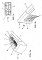
- FIGS. 2a to 2c A further embodiment of the storage device A according to the invention is shown in FIGS. 2a to 2c.
- the storage device A proposed here is essentially comparable to the embodiment according to FIGS. 1a to 1c.
- a longitudinal member 3 and a cross member 4 which is integrally formed and preferably made of a plastic.
- the embodiment proposed here has a frame 20 with an internal comb structure 21. Consequently, the combination of frames and strings spanned within the frame may be dispensed with.
- this embodiment also has a guide means according to the "comb principle" already described above.
- this embodiment can also be equipped with further guide means, as well as with a lock 13 and / or further longitudinal elements 3 and / or transverse elements 4.
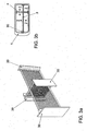
- FIGS. 3a and 3b a longitudinal element 3 and a transverse element 4 of a further embodiment of the proposed storage device A are depicted.
- the longitudinal element 3 and transverse element 4 proposed here has a further guide means, which is designed as a runner 30, in particular as a number of runners 30, which are respectively attached to the ends of the longitudinal element 3 and the transverse element 4 facing the wall of the receiving container 1.
- the runners 30 are adapted to slide on the wall of the receptacle 1. Also, they are set up not to tilt.
- the completely assembled arrangement of longitudinal element 3 and cross member 4 can be used directly in the receptacle 1 and lock for fixing in the upper region of the receptacle 1.
- FIG. 4a and 4b another guide means for a storage device A according to the invention is shown.
- the guide means proposed here essentially has a first U-shaped receiving frame 40 for a longitudinal element 3 and a second U-shaped receiving frame 41 for a transverse element 4.
- the U-shaped receiving frame 40, 41 has two side legs, 42 and a bottom leg 43.
- the bottom leg 43 of the U-shaped receiving frame 40, 41 is each equipped with a slot 44, 45. Through the slots 44, 45 of the receiving frame 40, 41 a split pin 46 is inserted, so that the receiving frame 40, 41 can be moved according to the orientation of the slots 40, 41.
- the split pin 46 may be provided with caps 47 so that the receiving frames 40, 41 are non-releasably but slidably connected together. It may further be provided that the split pin 46 is connected to the bottom of the receptacle 1, so that the receiving frame 40, 41 are equally connected to the receptacle 1.
- a longitudinal element 3 and a transverse element 4 can be inserted into the respective receiving frames 40, 41.
- the system proposed here can not tilt, since it is inside the walls of the receptacle. 1 to be led.
- the side legs 42 may be equipped with the skids 30 already proposed above, so that further results in an advantageous guide along the side walls of the receptacle 1.
- FIG. A guide means is provided here by the telescoping of the longitudinal elements 3 and transverse elements 4.
- the longitudinal elements 3 and the transverse elements 4 consist of a center piece 50 with four telescoping elements 51 aligned at right angles to each other.
- the arrangement of telescopic longitudinal and transverse elements is, as can be seen from Fig. 5, inserted into the receptacle 1.
- this embodiment is also provided with running rails 9 attached to the wall side of the receiving container, wherein at least the transverse element 4 and / or the longitudinal element 3 is equipped with a connecting element 10 that corresponds to the running rail 9.
- the middle piece 50 can be detected, for example, by the user and moved within the receptacle 1.
- the dimensions and position of the compartments 2, which are limited by the longitudinal and transverse elements 3,4 change.
- a Cartesian coordinate system set up within the storage device is assumed, a variability in the XZ and YZ plane can be ensured by the abovementioned embodiments of the storage device according to FIGS. 1a to 5. It can also be provided, as indicated for example in FIG. 1c, that a plurality of transverse elements 4, for example two transverse elements 4, are provided. Also, several longitudinal elements 3 may be provided.
- the storage device A proposed here essentially comprises a receptacle 1, as well as a number of transverse elements 4, which are received within the receptacle 1 in the manner of a hanging file.
- the transverse elements 4 divide the receptacle 1 into corresponding compartments 2, wherein the dimension of the compartments 2 can be changed by displacing the transverse elements 4.
- the transverse element 4 is essentially a planar element whose dimensions essentially correspond to the cross section of the receptacle 1.
- the hanging file is designed as a recess 11 in the upper edge region of the receptacle 1, wherein the transverse elements 4 are each equipped on the head side with lugs 12 which can be mounted in the upper edge region. Also conceivable are further guide means in the manner of the guide means already described above.
- the above-proposed storage facilities A depending on the application, be equipped with one or more of the above-described guide means.
- the proposed preferred embodiments represent only a selection of the conceivable combinations.
- FIGS. 7a and 7b A storage device A according to the invention for a center console is shown in FIGS. 7a and 7b.
- the storage device A essentially comprises a receptacle 1, as well as a folding element 70.
- the hinged element 70 is a flat element which can be folded about an axis 71, which preferably runs along the bottom of the receptacle 1.
- a preferred orientation of the axis 71 is the longitudinal direction of the receptacle 1, as seen in Fig. 7b.
- the folding element 70 can be set up optionally or lie flat on the floor.
- the receptacle 1 can optionally be divided into two compartments 2.
- the flap element 70 is equipped with a suitable locking device, which allows a releasable fixation in a raised position.
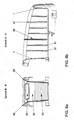
- the storage device A proposed here essentially comprises a trough-shaped receptacle 1, wherein at least one dividing element 80 is provided, which can subdivide the receptacle 1 into a number of compartments 2.
- the receptacle 1 is provided with a number of guide slots 81 which extend perpendicularly from the bottom of the receptacle 1 and are mounted on opposite sides of the walls of the receptacle 1.
- the guide slots are arranged on the walls along the longitudinal axis of the receptacle 1.
- the dividing elements 80 are configured telescopically.
- the dividing elements 80 comprise a mold half 82 and a telescopic wall 83, wherein the dividing elements 80 can be displaced into one another lengthwise.
- the mold half 82 is at least partially configured as a grip region 84.
- the advantage resulting from the telescopic dividing elements 80 becomes particularly clear when the receptacle 1 has different dimensions, in particular different heights along the longitudinal axis. It can be seen, for example, that the wall at the left end of the receptacle 1 is higher than at the right edge of the receptacle 1. The height of the side walls drops approximately uniformly along the longitudinal axis.
- the guide slots 81 have different lengths, wherein the dividing element 80 can be inserted into each guide slot 81 and can adapt to the respective length of the guide slot 81. Accordingly, only one kind of dividing element 80 needs to be stored. It is further provided that the dividing element 80 is equipped with a nose 85 which is suitable for insertion into a recess in the head region of the receptacle 1. The nose 85 acts as a stop, while the telescopic wall touches the bottom of the receptacle 1.
- the storage device according to the invention is used at a predetermined, usually fixed position within the center console of a motor vehicle.
- a center console M according to the invention is also conceivable, as suggested below for a center console M according to the invention.
- FIGS. 9a to 9c A center console M according to the invention, which follows a variable concept, is shown in FIGS. 9a to 9c.
- a center console M with a shaft 90 is proposed, wherein the shaft 90 is suitable for receiving at least two storage devices A.
- the well 90 is configured such that the storage devices A are stackable, i. can be recorded on top of each other. If, for example, different storage devices A are assumed, then the respective desired storage device A can be arranged in the topping area of the shaft 90, whereas the storage device or devices A not required are arranged below the topmost storage device A.
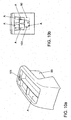
- FIGS. 10a and 10b A further center console M according to the invention is shown in FIGS. 10a and 10b. Again, a number of storage facilities A are housed in a center console M. It is proposed according to the invention to store the storage device A according to the principle of a paternoster lift 100 within a shaft 90 of the center console M. In the embodiment proposed here, for example, five storage devices A are provided, wherein two storage devices A are located in an upper, user-accessible part of the shaft 90. It can be seen that three further storage devices A are arranged in a lower region of the shaft 90. It is now possible and indicated in Fig.
- a manual drive device may be provided in the form of a handwheel 101, with which the storage device A on a predetermined railway can be moved.
- motor-driven drive systems are also conceivable.
- FIG. 11a and 11b Another center console is shown in Figs. 11a and 11b.
- the center console M has a slot 90 for receiving a number of storage devices A, wherein the storage devices A are pivotally received by an axle 110, wherein the axis 110 extends substantially transverse to the longitudinal axis of the center console M. Accordingly, the storage devices A can be pivoted overall as well as individually. According to the pivot position, the access to the respective storage device A is released or blocked.
- the storage device is equipped with a roller blind 111 or a similar locking mechanism. About the blind 111, the trough-shaped receptacle 1 can be closed or released.
Landscapes
- Engineering & Computer Science (AREA)
- Mechanical Engineering (AREA)
- Aviation & Aerospace Engineering (AREA)
- Transportation (AREA)
- Vehicle Step Arrangements And Article Storage (AREA)
Applications Claiming Priority (1)
| Application Number | Priority Date | Filing Date | Title |
|---|---|---|---|
| DE102006021685A DE102006021685A1 (de) | 2006-05-10 | 2006-05-10 | Aufbewahrungseinrichtung für eine Mittelkonsole eines Kraftfahrzeuges, sowie Mittelkonsole für ein Kraftfahrzeug |
Publications (3)
| Publication Number | Publication Date |
|---|---|
| EP1854672A2 true EP1854672A2 (fr) | 2007-11-14 |
| EP1854672A3 EP1854672A3 (fr) | 2009-09-09 |
| EP1854672B1 EP1854672B1 (fr) | 2012-06-13 |
Family
ID=38236473
Family Applications (1)
| Application Number | Title | Priority Date | Filing Date |
|---|---|---|---|
| EP07002245A Not-in-force EP1854672B1 (fr) | 2006-05-10 | 2007-02-02 | Dispositif de stockage pour une console intermédiaire de véhicule automobile et console intermédiaire pour véhicule automobile |
Country Status (2)
| Country | Link |
|---|---|
| EP (1) | EP1854672B1 (fr) |
| DE (1) | DE102006021685A1 (fr) |
Cited By (11)
| Publication number | Priority date | Publication date | Assignee | Title |
|---|---|---|---|---|
| GB2466357A (en) * | 2008-12-22 | 2010-06-23 | Gm Global Tech Operations Inc | A movable accommodation unit for a storage compartment of a vehicle |
| GB2469680A (en) * | 2009-04-24 | 2010-10-27 | Bentley Motors Ltd | Elongate storage compartment for a vehicle |
| FR2959185A1 (fr) * | 2010-04-26 | 2011-10-28 | Peugeot Citroen Automobiles Sa | Console centrale d'un vehicule automobile |
| DE102012020753A1 (de) * | 2012-10-23 | 2014-04-24 | GM Global Technology Operations LLC (n. d. Ges. d. Staates Delaware) | Becherhalter für ein Kraftfahrzeug |
| WO2015086633A1 (fr) * | 2013-12-11 | 2015-06-18 | Brose Fahrzeugteile Gmbh & Co. Kommanditgesellschaft, Coburg | Dispositif de rangement équipé d'un système d'acquisition d'images pour véhicule |
| EP3025906A1 (fr) * | 2014-10-30 | 2016-06-01 | Dr. Schneider Kunststoffwerke GmbH | Dispositif de reception de recipients de boissons et appareils electroniques |
| ES2586002A1 (es) * | 2016-08-29 | 2016-10-10 | Seat, S.A. | Dispositivo de almacenamiento para interior de un habitáculo de un vehículo |
| CN106829151A (zh) * | 2015-11-18 | 2017-06-13 | 福特全球技术公司 | 具有无限可调节存储分隔件系统的存储装置 |
| US9771026B2 (en) | 2014-08-21 | 2017-09-26 | Ford Global Technologies, Llc | Vehicle storage container |
| US10183625B2 (en) | 2017-02-08 | 2019-01-22 | Honda Motor Co., Ltd. | Armrest with adjustable cushions |
| DE102019208688A1 (de) * | 2019-06-14 | 2020-12-17 | Volkswagen Aktiengesellschaft | Ablagefach sowie Fahrzeug mit einem derartigen Ablagefach |
Families Citing this family (13)
| Publication number | Priority date | Publication date | Assignee | Title |
|---|---|---|---|---|
| DE102008049759A1 (de) * | 2008-09-30 | 2010-04-01 | GM Global Technology Operations, Inc., Detroit | Haltevorrichtung |
| DE102008063665A1 (de) * | 2008-12-18 | 2010-06-24 | Euwe Eugen Wexler Gmbh | Mittelkonsole eines Kraftfahrzeugs |
| DE102009043768A1 (de) * | 2009-09-30 | 2011-03-31 | GM Global Technology Operations, Inc., Detroit | Aufbewahrungsvorrichtung für Gegenstände in einem Kraftfahrzeug |
| DE102009043770A1 (de) * | 2009-09-30 | 2011-04-07 | GM Global Technology Operations, Inc., Detroit | Aufbewahrungsvorrichtung für Gegenstände in einem Kraftfahrzeug |
| DE102009043771A1 (de) * | 2009-09-30 | 2011-03-31 | GM Global Technology Operations, Inc., Detroit | Aufbewahrungsvorrichtung für Gegenstände in einem Kraftfahrzeug |
| DE102009049363A1 (de) | 2009-10-14 | 2011-04-21 | GM Global Technology Operations, Inc., Detroit | Aufbewahrungsvorrichtung für Gegenstände in einem Kraftfahrzeug |
| DE102009049364A1 (de) | 2009-10-14 | 2011-04-21 | GM Global Technology Operations, Inc., Detroit | Aufbewahrungsvorrichtung für Gegenstände in einem Kraftfahrzeug |
| DE102011100835B3 (de) * | 2011-05-07 | 2012-03-29 | Audi Ag | Ablagefach für ein Kraftfahrzeug |
| DE102013111555B4 (de) | 2013-10-21 | 2024-04-18 | Dr. Ing. H.C. F. Porsche Aktiengesellschaft | Ablagevorrichtung, Mittelkonsole und Querriegel |
| DE102015013242A1 (de) * | 2015-10-12 | 2017-04-13 | GM Global Technology Operations LLC (n. d. Ges. d. Staates Delaware) | Kraftfahrzeug mit Aufbewahrungssystem |
| DE102017129412B3 (de) | 2017-12-11 | 2019-05-29 | Dr. Schneider Kunststoffwerke Gmbh | Aufbewahrungseinrichtung |
| DE102022203153A1 (de) * | 2022-03-31 | 2023-10-05 | Psa Automobiles Sa | Stauraumanordnung für einen Innenraum eines Fahrzeugs, Fahrzeug mit der Stauraumanordnung und Verfahren zur Benutzung einer Stauraumanordnung |
| DE102023208103B3 (de) | 2023-08-24 | 2025-01-09 | Volkswagen Aktiengesellschaft | Stauraumvorrichtung und Kraftfahrzeug |
Family Cites Families (11)
| Publication number | Priority date | Publication date | Assignee | Title |
|---|---|---|---|---|
| DE9202354U1 (de) * | 1992-02-24 | 1993-06-17 | fischerwerke Artur Fischer GmbH & Co KG, 7244 Waldachtal | Aufbewahrungsbehälter, insbesondere für den Einbau in ein Aufnahmefach eines Kraftfahrzeuges |
| DE4409562C1 (de) * | 1994-03-21 | 1995-04-27 | Daimler Benz Ag | Ablagefach für Fahrzeuginnenräume |
| JPH08238969A (ja) * | 1995-03-07 | 1996-09-17 | Nifco Inc | 車両用飲料容器ホルダ |
| JPH1024770A (ja) * | 1996-07-08 | 1998-01-27 | Kojima Press Co Ltd | 車両用コンソールボックス |
| DE10027373B4 (de) * | 2000-06-02 | 2009-03-05 | Lisa Dräxlmaier GmbH | Warenaufbewahrungsbehältnis für ein Kraftfahrzeug |
| KR100535596B1 (ko) * | 2003-10-02 | 2005-12-08 | 현대자동차주식회사 | 이동식 컵지지대를 가지는 컵홀더 |
| DE102004011306A1 (de) * | 2004-03-09 | 2005-09-29 | Fischer Automotive Systems Gmbh | Ablagefach für ein Kraftfahrzeug |
| DE102004029864A1 (de) * | 2004-06-21 | 2006-01-12 | Daimlerchrysler Ag | Mittelkonsole für ein Kraftfahrzeug |
| DE202004011589U1 (de) * | 2004-07-23 | 2005-12-08 | Fischer Automotive Systems Gmbh | Ablage für einen Kraftwagen |
| DE102004051443A1 (de) * | 2004-10-22 | 2006-04-27 | Bayerische Motoren Werke Ag | Aufnahmeelement für einen Cupholder mit einer integrierten Ablage, insbes. für Kraftfahrzeuge |
| DE102006030474A1 (de) * | 2006-07-01 | 2008-01-03 | GM Global Technology Operations, Inc., Detroit | Mehrteilige Konsole für ein Kraftfahrzeug |
-
2006
- 2006-05-10 DE DE102006021685A patent/DE102006021685A1/de not_active Withdrawn
-
2007
- 2007-02-02 EP EP07002245A patent/EP1854672B1/fr not_active Not-in-force
Non-Patent Citations (1)
| Title |
|---|
| None |
Cited By (19)
| Publication number | Priority date | Publication date | Assignee | Title |
|---|---|---|---|---|
| GB2466357A (en) * | 2008-12-22 | 2010-06-23 | Gm Global Tech Operations Inc | A movable accommodation unit for a storage compartment of a vehicle |
| US8480151B2 (en) | 2008-12-22 | 2013-07-09 | GM Global Technology Operations LLC | Accommodation unit for storage compartment and storage compartment |
| GB2466357B (en) * | 2008-12-22 | 2013-09-25 | Gm Global Tech Operations Inc | Accomodation unit for storage compartment and storage compartment |
| GB2469680A (en) * | 2009-04-24 | 2010-10-27 | Bentley Motors Ltd | Elongate storage compartment for a vehicle |
| GB2469680B (en) * | 2009-04-24 | 2013-12-18 | Bentley Motors Ltd | Vehicle storage compartment divider |
| FR2959185A1 (fr) * | 2010-04-26 | 2011-10-28 | Peugeot Citroen Automobiles Sa | Console centrale d'un vehicule automobile |
| US9180806B2 (en) | 2012-10-23 | 2015-11-10 | GM Global Technology Operations LLC | Cup holder for a motor vehicle |
| DE102012020753A1 (de) * | 2012-10-23 | 2014-04-24 | GM Global Technology Operations LLC (n. d. Ges. d. Staates Delaware) | Becherhalter für ein Kraftfahrzeug |
| WO2015086633A1 (fr) * | 2013-12-11 | 2015-06-18 | Brose Fahrzeugteile Gmbh & Co. Kommanditgesellschaft, Coburg | Dispositif de rangement équipé d'un système d'acquisition d'images pour véhicule |
| US10059262B2 (en) | 2013-12-11 | 2018-08-28 | Brose Fahrzeugteile Gmbh & Co. Kommanditgesellschaft, Coburg | Storage device for a vehicle with an image-capturing device |
| US9771026B2 (en) | 2014-08-21 | 2017-09-26 | Ford Global Technologies, Llc | Vehicle storage container |
| EP3025906A1 (fr) * | 2014-10-30 | 2016-06-01 | Dr. Schneider Kunststoffwerke GmbH | Dispositif de reception de recipients de boissons et appareils electroniques |
| CN106829151A (zh) * | 2015-11-18 | 2017-06-13 | 福特全球技术公司 | 具有无限可调节存储分隔件系统的存储装置 |
| US10336504B2 (en) | 2015-11-18 | 2019-07-02 | Ford Global Technologies, Llc | Storage device with infinitely adjustable storage divider system |
| CN106829151B (zh) * | 2015-11-18 | 2021-01-12 | 福特全球技术公司 | 具有无限可调节存储分隔件系统的存储装置 |
| ES2586002A1 (es) * | 2016-08-29 | 2016-10-10 | Seat, S.A. | Dispositivo de almacenamiento para interior de un habitáculo de un vehículo |
| US10183625B2 (en) | 2017-02-08 | 2019-01-22 | Honda Motor Co., Ltd. | Armrest with adjustable cushions |
| DE102019208688A1 (de) * | 2019-06-14 | 2020-12-17 | Volkswagen Aktiengesellschaft | Ablagefach sowie Fahrzeug mit einem derartigen Ablagefach |
| DE102019208688B4 (de) | 2019-06-14 | 2024-03-07 | Volkswagen Aktiengesellschaft | Ablagefach sowie Fahrzeug mit einem derartigen Ablagefach |
Also Published As
| Publication number | Publication date |
|---|---|
| EP1854672B1 (fr) | 2012-06-13 |
| DE102006021685A1 (de) | 2007-11-15 |
| EP1854672A3 (fr) | 2009-09-09 |
Similar Documents
| Publication | Publication Date | Title |
|---|---|---|
| EP1854672B1 (fr) | Dispositif de stockage pour une console intermédiaire de véhicule automobile et console intermédiaire pour véhicule automobile | |
| EP3478533B1 (fr) | Dispositif de réglage en longueur et siège de véhicule | |
| DE102015219472B4 (de) | Längsverstellvorrichtung für einen Fahrzeugsitz, Schienenpaar und Fahrzeugsitz | |
| DE102020105202A1 (de) | Vorrichtung zur translatorischen und rotatorischen Bewegung eines Gegenstands relativ zu einer Trägerplatte | |
| EP2292468B1 (fr) | Surface de chargement en plusieurs parties et déplaçable | |
| EP3587294A1 (fr) | Récipient empilable pourvu de mécanisme de raccordement | |
| DE102008061106A1 (de) | Laderaumabdeckung für ein Fahrzeug | |
| DE112008004018B4 (de) | Armlehne für Kraftfahrzeug | |
| EP1190664B1 (fr) | Dispositif de liaison pour un chariot de nettoyage | |
| DE102014220476B4 (de) | Längsversteller mit Sperrmechanismus | |
| DE102020106035A1 (de) | Fluggastsitz mit einer Verbindungsvorrichtung sowie Sitzreihe | |
| DE102021133322A1 (de) | Automobil mit Regal im Laderaum | |
| DE102015112843B4 (de) | Runge für einen Nutzfahrzeugaufbau sowie Ladungssicherungssystem, Nutzfahrzeugaufbau und Nutzfahrzeug mit einer solchen Runge | |
| DE102021109542A1 (de) | Stabiler Aufbewahrungsbehälter mit flexibler Einteilung des Innenraums | |
| EP1084659B1 (fr) | Unité d'assemblage | |
| DE202005018504U1 (de) | Schublade und Werkstattwagen | |
| EP2815923B1 (fr) | Compartiment coulissant dans un coffre de vehicule automobile | |
| DE102021114154B3 (de) | Ablage für ein fahrzeug | |
| DE202022001906U1 (de) | Schubladenvorrichtung zur nachträglichen Montage in eine Möbeleinrichtung | |
| DE102010015799A1 (de) | Höheneinstellbare Aufnahme einer Lagerung eines Bett- oder Untermatratzenbauteils | |
| DE102020114068A1 (de) | Aufsatzrahmen für eine Palette und/oder eine Platte zur Auflage auf die Oberfläche eines Palettenoberdecks einer Palette | |
| DE102005017145B4 (de) | Verfahrbare Kletterwand | |
| DE102020205304A1 (de) | Bodenbaugruppe für ein Kraftfahrzeug sowie ein System und ein Kraftfahrzeug | |
| EP0286811A1 (fr) | Recouvrement téléscopique | |
| DE2709889C3 (de) | Ringbuchheftvorrichtung |
Legal Events
| Date | Code | Title | Description |
|---|---|---|---|
| PUAI | Public reference made under article 153(3) epc to a published international application that has entered the european phase |
Free format text: ORIGINAL CODE: 0009012 |
|
| AK | Designated contracting states |
Kind code of ref document: A2 Designated state(s): AT BE BG CH CY CZ DE DK EE ES FI FR GB GR HU IE IS IT LI LT LU LV MC NL PL PT RO SE SI SK TR |
|
| AX | Request for extension of the european patent |
Extension state: AL BA HR MK YU |
|
| PUAL | Search report despatched |
Free format text: ORIGINAL CODE: 0009013 |
|
| AK | Designated contracting states |
Kind code of ref document: A3 Designated state(s): AT BE BG CH CY CZ DE DK EE ES FI FR GB GR HU IE IS IT LI LT LU LV MC NL PL PT RO SE SI SK TR |
|
| AX | Request for extension of the european patent |
Extension state: AL BA HR MK RS |
|
| 17P | Request for examination filed |
Effective date: 20100309 |
|
| 17Q | First examination report despatched |
Effective date: 20100412 |
|
| AKX | Designation fees paid |
Designated state(s): AT BE BG CH CY CZ DE DK EE ES FI FR GB GR HU IE IS IT LI LT LU LV MC NL PL PT RO SE SI SK TR |
|
| REG | Reference to a national code |
Ref country code: DE Ref legal event code: R079 Ref document number: 502007010014 Country of ref document: DE Free format text: PREVIOUS MAIN CLASS: B60R0007040000 Ipc: B60N0002460000 |
|
| GRAP | Despatch of communication of intention to grant a patent |
Free format text: ORIGINAL CODE: EPIDOSNIGR1 |
|
| RIC1 | Information provided on ipc code assigned before grant |
Ipc: B60R 7/04 20060101ALI20120102BHEP Ipc: B60N 2/46 20060101AFI20120102BHEP |
|
| GRAS | Grant fee paid |
Free format text: ORIGINAL CODE: EPIDOSNIGR3 |
|
| GRAA | (expected) grant |
Free format text: ORIGINAL CODE: 0009210 |
|
| AK | Designated contracting states |
Kind code of ref document: B1 Designated state(s): AT BE BG CH CY CZ DE DK EE ES FI FR GB GR HU IE IS IT LI LT LU LV MC NL PL PT RO SE SI SK TR |
|
| REG | Reference to a national code |
Ref country code: GB Ref legal event code: FG4D Free format text: NOT ENGLISH |
|
| REG | Reference to a national code |
Ref country code: CH Ref legal event code: EP Ref country code: AT Ref legal event code: REF Ref document number: 561833 Country of ref document: AT Kind code of ref document: T Effective date: 20120615 |
|
| RAP2 | Party data changed (patent owner data changed or rights of a patent transferred) |
Owner name: VOLKSWAGEN AKTIENGESELLSCHAFT |
|
| REG | Reference to a national code |
Ref country code: IE Ref legal event code: FG4D Free format text: LANGUAGE OF EP DOCUMENT: GERMAN |
|
| REG | Reference to a national code |
Ref country code: DE Ref legal event code: R096 Ref document number: 502007010014 Country of ref document: DE Effective date: 20120809 |
|
| REG | Reference to a national code |
Ref country code: NL Ref legal event code: VDEP Effective date: 20120613 |
|
| PG25 | Lapsed in a contracting state [announced via postgrant information from national office to epo] |
Ref country code: FI Free format text: LAPSE BECAUSE OF FAILURE TO SUBMIT A TRANSLATION OF THE DESCRIPTION OR TO PAY THE FEE WITHIN THE PRESCRIBED TIME-LIMIT Effective date: 20120613 Ref country code: SE Free format text: LAPSE BECAUSE OF FAILURE TO SUBMIT A TRANSLATION OF THE DESCRIPTION OR TO PAY THE FEE WITHIN THE PRESCRIBED TIME-LIMIT Effective date: 20120613 Ref country code: LT Free format text: LAPSE BECAUSE OF FAILURE TO SUBMIT A TRANSLATION OF THE DESCRIPTION OR TO PAY THE FEE WITHIN THE PRESCRIBED TIME-LIMIT Effective date: 20120613 Ref country code: CY Free format text: LAPSE BECAUSE OF FAILURE TO SUBMIT A TRANSLATION OF THE DESCRIPTION OR TO PAY THE FEE WITHIN THE PRESCRIBED TIME-LIMIT Effective date: 20120613 |
|
| REG | Reference to a national code |
Ref country code: LT Ref legal event code: MG4D Effective date: 20120627 |
|
| PG25 | Lapsed in a contracting state [announced via postgrant information from national office to epo] |
Ref country code: LV Free format text: LAPSE BECAUSE OF FAILURE TO SUBMIT A TRANSLATION OF THE DESCRIPTION OR TO PAY THE FEE WITHIN THE PRESCRIBED TIME-LIMIT Effective date: 20120613 Ref country code: GR Free format text: LAPSE BECAUSE OF FAILURE TO SUBMIT A TRANSLATION OF THE DESCRIPTION OR TO PAY THE FEE WITHIN THE PRESCRIBED TIME-LIMIT Effective date: 20120914 Ref country code: SI Free format text: LAPSE BECAUSE OF FAILURE TO SUBMIT A TRANSLATION OF THE DESCRIPTION OR TO PAY THE FEE WITHIN THE PRESCRIBED TIME-LIMIT Effective date: 20120613 |
|
| REG | Reference to a national code |
Ref country code: DE Ref legal event code: R084 Ref document number: 502007010014 Country of ref document: DE |
|
| PG25 | Lapsed in a contracting state [announced via postgrant information from national office to epo] |
Ref country code: CZ Free format text: LAPSE BECAUSE OF FAILURE TO SUBMIT A TRANSLATION OF THE DESCRIPTION OR TO PAY THE FEE WITHIN THE PRESCRIBED TIME-LIMIT Effective date: 20120613 Ref country code: EE Free format text: LAPSE BECAUSE OF FAILURE TO SUBMIT A TRANSLATION OF THE DESCRIPTION OR TO PAY THE FEE WITHIN THE PRESCRIBED TIME-LIMIT Effective date: 20120613 Ref country code: RO Free format text: LAPSE BECAUSE OF FAILURE TO SUBMIT A TRANSLATION OF THE DESCRIPTION OR TO PAY THE FEE WITHIN THE PRESCRIBED TIME-LIMIT Effective date: 20120613 Ref country code: SK Free format text: LAPSE BECAUSE OF FAILURE TO SUBMIT A TRANSLATION OF THE DESCRIPTION OR TO PAY THE FEE WITHIN THE PRESCRIBED TIME-LIMIT Effective date: 20120613 Ref country code: IS Free format text: LAPSE BECAUSE OF FAILURE TO SUBMIT A TRANSLATION OF THE DESCRIPTION OR TO PAY THE FEE WITHIN THE PRESCRIBED TIME-LIMIT Effective date: 20121013 |
|
| PG25 | Lapsed in a contracting state [announced via postgrant information from national office to epo] |
Ref country code: PT Free format text: LAPSE BECAUSE OF FAILURE TO SUBMIT A TRANSLATION OF THE DESCRIPTION OR TO PAY THE FEE WITHIN THE PRESCRIBED TIME-LIMIT Effective date: 20121015 Ref country code: IT Free format text: LAPSE BECAUSE OF FAILURE TO SUBMIT A TRANSLATION OF THE DESCRIPTION OR TO PAY THE FEE WITHIN THE PRESCRIBED TIME-LIMIT Effective date: 20120613 Ref country code: PL Free format text: LAPSE BECAUSE OF FAILURE TO SUBMIT A TRANSLATION OF THE DESCRIPTION OR TO PAY THE FEE WITHIN THE PRESCRIBED TIME-LIMIT Effective date: 20120613 |
|
| REG | Reference to a national code |
Ref country code: DE Ref legal event code: R084 Ref document number: 502007010014 Country of ref document: DE Effective date: 20130125 |
|
| PG25 | Lapsed in a contracting state [announced via postgrant information from national office to epo] |
Ref country code: NL Free format text: LAPSE BECAUSE OF FAILURE TO SUBMIT A TRANSLATION OF THE DESCRIPTION OR TO PAY THE FEE WITHIN THE PRESCRIBED TIME-LIMIT Effective date: 20120613 |
|
| PLBE | No opposition filed within time limit |
Free format text: ORIGINAL CODE: 0009261 |
|
| STAA | Information on the status of an ep patent application or granted ep patent |
Free format text: STATUS: NO OPPOSITION FILED WITHIN TIME LIMIT |
|
| PG25 | Lapsed in a contracting state [announced via postgrant information from national office to epo] |
Ref country code: DK Free format text: LAPSE BECAUSE OF FAILURE TO SUBMIT A TRANSLATION OF THE DESCRIPTION OR TO PAY THE FEE WITHIN THE PRESCRIBED TIME-LIMIT Effective date: 20120613 Ref country code: ES Free format text: LAPSE BECAUSE OF FAILURE TO SUBMIT A TRANSLATION OF THE DESCRIPTION OR TO PAY THE FEE WITHIN THE PRESCRIBED TIME-LIMIT Effective date: 20120924 |
|
| 26N | No opposition filed |
Effective date: 20130314 |
|
| REG | Reference to a national code |
Ref country code: DE Ref legal event code: R097 Ref document number: 502007010014 Country of ref document: DE Effective date: 20130314 |
|
| PG25 | Lapsed in a contracting state [announced via postgrant information from national office to epo] |
Ref country code: BG Free format text: LAPSE BECAUSE OF FAILURE TO SUBMIT A TRANSLATION OF THE DESCRIPTION OR TO PAY THE FEE WITHIN THE PRESCRIBED TIME-LIMIT Effective date: 20120913 |
|
| BERE | Be: lapsed |
Owner name: VOLKSWAGEN A.G. Effective date: 20130228 |
|
| PG25 | Lapsed in a contracting state [announced via postgrant information from national office to epo] |
Ref country code: MC Free format text: LAPSE BECAUSE OF NON-PAYMENT OF DUE FEES Effective date: 20130228 |
|
| REG | Reference to a national code |
Ref country code: CH Ref legal event code: PL |
|
| PG25 | Lapsed in a contracting state [announced via postgrant information from national office to epo] |
Ref country code: CH Free format text: LAPSE BECAUSE OF NON-PAYMENT OF DUE FEES Effective date: 20130228 Ref country code: LI Free format text: LAPSE BECAUSE OF NON-PAYMENT OF DUE FEES Effective date: 20130228 |
|
| REG | Reference to a national code |
Ref country code: IE Ref legal event code: MM4A |
|
| PG25 | Lapsed in a contracting state [announced via postgrant information from national office to epo] |
Ref country code: BE Free format text: LAPSE BECAUSE OF NON-PAYMENT OF DUE FEES Effective date: 20130228 Ref country code: IE Free format text: LAPSE BECAUSE OF NON-PAYMENT OF DUE FEES Effective date: 20130202 |
|
| REG | Reference to a national code |
Ref country code: AT Ref legal event code: MM01 Ref document number: 561833 Country of ref document: AT Kind code of ref document: T Effective date: 20130202 |
|
| PG25 | Lapsed in a contracting state [announced via postgrant information from national office to epo] |
Ref country code: AT Free format text: LAPSE BECAUSE OF NON-PAYMENT OF DUE FEES Effective date: 20130202 |
|
| PG25 | Lapsed in a contracting state [announced via postgrant information from national office to epo] |
Ref country code: TR Free format text: LAPSE BECAUSE OF FAILURE TO SUBMIT A TRANSLATION OF THE DESCRIPTION OR TO PAY THE FEE WITHIN THE PRESCRIBED TIME-LIMIT Effective date: 20120613 |
|
| PG25 | Lapsed in a contracting state [announced via postgrant information from national office to epo] |
Ref country code: LU Free format text: LAPSE BECAUSE OF NON-PAYMENT OF DUE FEES Effective date: 20130202 Ref country code: HU Free format text: LAPSE BECAUSE OF FAILURE TO SUBMIT A TRANSLATION OF THE DESCRIPTION OR TO PAY THE FEE WITHIN THE PRESCRIBED TIME-LIMIT; INVALID AB INITIO Effective date: 20070202 |
|
| REG | Reference to a national code |
Ref country code: FR Ref legal event code: PLFP Year of fee payment: 10 |
|
| PGFP | Annual fee paid to national office [announced via postgrant information from national office to epo] |
Ref country code: GB Payment date: 20160226 Year of fee payment: 10 Ref country code: FR Payment date: 20160229 Year of fee payment: 10 |
|
| GBPC | Gb: european patent ceased through non-payment of renewal fee |
Effective date: 20170202 |
|
| REG | Reference to a national code |
Ref country code: DE Ref legal event code: R079 Ref document number: 502007010014 Country of ref document: DE Free format text: PREVIOUS MAIN CLASS: B60N0002460000 Ipc: B60N0002750000 |
|
| REG | Reference to a national code |
Ref country code: FR Ref legal event code: ST Effective date: 20171031 |
|
| PG25 | Lapsed in a contracting state [announced via postgrant information from national office to epo] |
Ref country code: FR Free format text: LAPSE BECAUSE OF NON-PAYMENT OF DUE FEES Effective date: 20170228 |
|
| PG25 | Lapsed in a contracting state [announced via postgrant information from national office to epo] |
Ref country code: GB Free format text: LAPSE BECAUSE OF NON-PAYMENT OF DUE FEES Effective date: 20170202 |
|
| PGFP | Annual fee paid to national office [announced via postgrant information from national office to epo] |
Ref country code: DE Payment date: 20210228 Year of fee payment: 15 |
|
| REG | Reference to a national code |
Ref country code: DE Ref legal event code: R119 Ref document number: 502007010014 Country of ref document: DE |
|
| PG25 | Lapsed in a contracting state [announced via postgrant information from national office to epo] |
Ref country code: DE Free format text: LAPSE BECAUSE OF NON-PAYMENT OF DUE FEES Effective date: 20220901 |