EP1854773A1 - Corps fritte avec entretoises et son procede de production et de jonction - Google Patents
Corps fritte avec entretoises et son procede de production et de jonction Download PDFInfo
- Publication number
- EP1854773A1 EP1854773A1 EP06715104A EP06715104A EP1854773A1 EP 1854773 A1 EP1854773 A1 EP 1854773A1 EP 06715104 A EP06715104 A EP 06715104A EP 06715104 A EP06715104 A EP 06715104A EP 1854773 A1 EP1854773 A1 EP 1854773A1
- Authority
- EP
- European Patent Office
- Prior art keywords
- spacers
- sintered
- side faces
- bodies
- main body
- Prior art date
- Legal status (The legal status is an assumption and is not a legal conclusion. Google has not performed a legal analysis and makes no representation as to the accuracy of the status listed.)
- Withdrawn
Links
Images


Classifications
-
- F—MECHANICAL ENGINEERING; LIGHTING; HEATING; WEAPONS; BLASTING
- F01—MACHINES OR ENGINES IN GENERAL; ENGINE PLANTS IN GENERAL; STEAM ENGINES
- F01N—GAS-FLOW SILENCERS OR EXHAUST APPARATUS FOR MACHINES OR ENGINES IN GENERAL; GAS-FLOW SILENCERS OR EXHAUST APPARATUS FOR INTERNAL-COMBUSTION ENGINES
- F01N3/00—Exhaust or silencing apparatus having means for purifying, rendering innocuous, or otherwise treating exhaust
- F01N3/02—Exhaust or silencing apparatus having means for purifying, rendering innocuous, or otherwise treating exhaust for cooling, or for removing solid constituents of, exhaust
- F01N3/021—Exhaust or silencing apparatus having means for purifying, rendering innocuous, or otherwise treating exhaust for cooling, or for removing solid constituents of, exhaust by means of filters
- F01N3/022—Exhaust or silencing apparatus having means for purifying, rendering innocuous, or otherwise treating exhaust for cooling, or for removing solid constituents of, exhaust by means of filters characterised by specially adapted filtering structure, e.g. honeycomb, mesh or fibrous
- F01N3/0222—Exhaust or silencing apparatus having means for purifying, rendering innocuous, or otherwise treating exhaust for cooling, or for removing solid constituents of, exhaust by means of filters characterised by specially adapted filtering structure, e.g. honeycomb, mesh or fibrous the structure being monolithic, e.g. honeycombs
-
- B—PERFORMING OPERATIONS; TRANSPORTING
- B01—PHYSICAL OR CHEMICAL PROCESSES OR APPARATUS IN GENERAL
- B01D—SEPARATION
- B01D46/00—Filters or filtering processes specially modified for separating dispersed particles from gases or vapours
- B01D46/24—Particle separators, e.g. dust precipitators, using rigid hollow filter bodies
- B01D46/2403—Particle separators, e.g. dust precipitators, using rigid hollow filter bodies characterised by the physical shape or structure of the filtering element
- B01D46/2418—Honeycomb filters
- B01D46/2422—Mounting of the body within a housing
-
- Y—GENERAL TAGGING OF NEW TECHNOLOGICAL DEVELOPMENTS; GENERAL TAGGING OF CROSS-SECTIONAL TECHNOLOGIES SPANNING OVER SEVERAL SECTIONS OF THE IPC; TECHNICAL SUBJECTS COVERED BY FORMER USPC CROSS-REFERENCE ART COLLECTIONS [XRACs] AND DIGESTS
- Y02—TECHNOLOGIES OR APPLICATIONS FOR MITIGATION OR ADAPTATION AGAINST CLIMATE CHANGE
- Y02T—CLIMATE CHANGE MITIGATION TECHNOLOGIES RELATED TO TRANSPORTATION
- Y02T10/00—Road transport of goods or passengers
- Y02T10/10—Internal combustion engine [ICE] based vehicles
- Y02T10/12—Improving ICE efficiencies
-
- Y—GENERAL TAGGING OF NEW TECHNOLOGICAL DEVELOPMENTS; GENERAL TAGGING OF CROSS-SECTIONAL TECHNOLOGIES SPANNING OVER SEVERAL SECTIONS OF THE IPC; TECHNICAL SUBJECTS COVERED BY FORMER USPC CROSS-REFERENCE ART COLLECTIONS [XRACs] AND DIGESTS
- Y10—TECHNICAL SUBJECTS COVERED BY FORMER USPC
- Y10T—TECHNICAL SUBJECTS COVERED BY FORMER US CLASSIFICATION
- Y10T428/00—Stock material or miscellaneous articles
- Y10T428/24—Structurally defined web or sheet [e.g., overall dimension, etc.]
- Y10T428/24149—Honeycomb-like
Definitions
- the present invention relates to a sintered body with spacers comprising a sintered body obtained by sintering a molded body and spacers formed on the sintered body, to its production method and bonding method, and to a ceramic honeycomb filter.
- DPFs diesel particulate filters
- a ceramic filter made of a non-oxide material such as a silicon carbide material or a silicon nitride material.
- the filter e.g. soot in the exhaust gas is accumulated in the filter. Accordingly, it is necessary to increase the exhaust gas temperature (for example, 500°C to 1,000°C) to burn this e.g. soot to improve filtering efficiency.
- a thermal stress increases and repeat of such a high-temperature treatment may cause a heat shock, which may cause e.g. a crack.
- a filter is proposed which is constituted by a plurality of sintered bodies bonded together to reduce heat expansion or heat shrinkage by such a heat shock.
- Patent Document 1 describes a ceramic structure.
- the ceramic structure is constituted by a plurality of porous ceramic members bound together via an adhesive layer, and distance-keeping members are interposed between the porous ceramic members bound.
- each of such porous ceramic members has sintering deformation due to e.g. shrinkage at the time of sintering
- the porous ceramic member is not an ideal rectangular solid but its side faces are warped. Accordingly, even when only such distance-keeping members of cylindrical shape or a rectangular column shape are provided on such warped side faces to maintain the distance, adjacent porous ceramic members are not straightly arranged but they are inclined, and thus, they are not bonded as they are aligned straightly in the same direction.
- Patent Document 1 JP-A-2002-102627
- the present invention provides, in order to achieve the above object, a sintered body with spacers comprising a sintered main body of column shape having both ends opening in a honeycomb shape and having a rectangular cross-section, and spacers provided on side faces of the sintered main body, wherein the spacers are provided on at least opposing two side faces among four side faces of the sintered main body, and wherein planes defined by top faces of the spacers on the respective side faces are parallel with each other.
- the present invention is characterized in that the spacers are provided on the four side faces, and an imaginary cross-section defined by top faces of the spacers is a rectangle or a square.
- the present invention provides a process for producing a sintered body with spacers, comprising a step of applying pasty spacers at predetermined positions of four side faces of a sintered main body of column shape having both ends opening in a honeycomb shape and having a rectangular cross-section, a step of setting the sintered main body in a molding frame having a rectangular hollow cross-section enclosed by four planes, and a step of drying and solidifying the spacers.
- the present invention provides the method for bonding the sintered bodies with spacers, wherein the spacers are provided on predetermined positions of four side faces of the sintered main body of each of the sintered bodies, and the method comprises a step of bonding adjacent sintered bodies in a state that their spacers are contact with each other.
- adjacent sintered bodies are bonded so that their center positions in their longitudinal directions are aligned.
- the present invention provides a ceramic honeycomb filter which is formed by machining a bonded body comprising a plurality of sintered bodies bonded by the bonding method of sintered bodies with spacers.
- the sintered bodies can be piled up without being inclined when they are piled up as they are in laying positions.
- the sintered bodies can be piled up without being inclined when they are piled up as they are in laying positions.
- the spacers are formed on all of four side faces of each sintered main bodies, a cross-section of an imaginary rectangular column defined by top faces of the spacers, becomes rectangle or square, and thus, the sintered bodies can be three-dimensionally piled up with good dimension accuracy, and a large sized filter excellent in dimension accuracy can be easily produced.
- each of the sintered main bodies having four side faces applied with pasty spacers is set in a molding frame having a rectangular hollow cross-section, and the pasty spacers are dried to be solidified in this state, whereby top faces of the spacers formed on the four side faces of the sintered main body define a part of side faces of an imaginary rectangular column having a rectangular cross-section.
- sintered bodies having side faces provided with spacers are bonded so that spacers of adjacent sintered bodies are contact with each other, and thus, when a large number of sintered bodies are arranged vertically or horizontally, they can be bonded as they are aligned in one direction without being distorted or inclined in vertical or lateral direction.
- a bonded body in which sintered bodies each having an accurate external shape of imaginary rectangular solid or square column defined by spacers, are bonded as they are aligned in one direction, is machined, and thus, a large-sized filter to be used for e.g. buses or trucks formed by bonding a plurality of sintered bodies as they are aligned in vertical and lateral directions, can be formed with good accuracy. Further, since such a filter is formed by bonding a plurality of sintered bodies, it is possible to reduce a heat shock at a time of using the filter, to reduce occurrence of e.g. cracks.
- FIG. 1 shows a sintered body with spacers according to the present invention, wherein Fig. 1(A) is a perspective view and Fig. 1(B) is a front view.
- the sintered body 1 with spacers according to the present invention is constituted by a sintered main body 2 and spacers 3.
- the sintered main body 2 has a column shape having a substantially rectangular (square or rectangular) cross-section, which has a plurality of through holes 4 perforating through both ends so that the cross-section (end faces) has a grating shape.
- both ends of the sintered main body 2 are each opened in a honeycomb shape of grating by the plurality of through holes 4.
- the through holes 4 are filled with sealing members 5 so that both end faces (inlet side and outlet side) of the sintered main body 2 becomes a hound's tooth pattern or a checkerboard pattern as shown in Fig. 1.
- the sealing members 5 fill different through holes 4 between the ends of inlet side and outlet side. Namely, a through hole 4 whose inlet side is sealed has an opening outlet side and a through hole 4 whose inlet side is open has a sealed outlet side. Partitions between adjacent through holes 4 are made of porous sintered body.
- an exhaust gas flows into through holes 4 opening in the inlet side and as it flows through the through holes 4, moves into adjacent through holes 4 through a filter made of a porous sintered body as partitions between the through holes 4, whereby e.g. a soot is removed by the filter and the gas is exhausted through the through holes 4 opening to the outlet side as a cleaned air.
- filling of the sealing members 5 may be carried out before or after the forming of spacers, and is not particularly limited.
- a plurality of spacers 3 are provided at predetermined positions of each of four side faces of the square column-shaped sintered main body 2 (4 spacers in each side face in the Figure).
- the spacers 3 are provided at positions of side faces of adjacent sintered main bodies 2 substantially corresponding to each other so that the spacers of the adjacent sintered main bodies 2 are contact with each other.
- the positions in the side faces of the sintered main bodies 2 at which the spacers 3 are provided are not particularly limited, but it is preferred to provide a plurality of spacers as they are distributed as uniformly as possible on the side faces. Specifically, when four spacers are provided on each side face, they are preferably provided in the corners of the side face.
- the spacers 3 each has a projecting shape having a flat top face (leading edge face), they have different heights according to irregular shapes of side faces of the sintered main body 2, and the top faces of the four spacers 3 in each side face share a common plane.
- planes defined by top faces of spacers on opposing two side faces of the sintered main body 2 are parallel with each other.
- four planes defined by spacers 3 of four side faces constitutes a virtual rectangular column having a rectangular cross-section. Namely, top faces of a plurality of spacers 3 provided on a side face of a sintered body 2 defines a common plane, and planes defined by top faces of spacers 3 of adjacent side faces, are perpendicular to each other. Accordingly, the outer shape defined by top faces of spacers 3 of four side faces, becomes a square column having a rectangular (square in the Figure) cross-section (virtual cross-section) as represented by the dotted line 13 of Fig. 1(B).
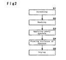
- FIG. 2 is a flow chart showing the process of producing a sintered body with spacers according to the present invention. Each step is described with reference to Fig. 2.
- Sintered main bodies of square column shape molded are screened according to the size of square cross-section into groups having predetermined sizes.
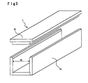
- the screening can be carried out, for example, by using a screening jig of gutter shape as shown in Fig. 3.
- the screening jig 6 is constituted by a gutter 6a having a predetermined width W.
- a plurality of gutters 6a having different Ws are prepared in advance.
- the sintered main bodies 2 are put into the gutter 6a to be screened according to their cross-sectional vertical and lateral dimensions into a group accommodable in the gutter and a group not accommodable in the gutter.
- the sintered main bodies not accommodable in the gutter can be further screened in the same manner using a different gutter 6a to be grouped according to the degree of deformation of the outer shape.
- a cap 6b to the gutter 6a containing a sintered main body, it is possible to screen the sintered main bodies by the vertical dimensions at the same time.
- the size of sintered bodies to be bonded can be unified to a certain extent before the bonding of sintered bodies to be described later, and it is possible to improve dimension accuracy of bonded body. Further, by appropriately selecting sintered bodies whose dimensions are screened before bonding, it is possible to attempt improvement of yield.
- Both ends of a sintered main body are applied with masking.
- its both ends are covered with e.g. a sheet in order to prevent bonding agent from being forced out to choke through holes at a time of bonding the sintered bodies to be described later.
- Pasty spacers are applied on four side faces of each sintered main body.
- the spacers are made of a kneaded material not dried, and applied to predetermined positions of each side face.
- the pasty spacers are provided at four separate positions in each side face in Fig. 1, but the positions are not limited thereto.
- the number of spacers provided on each side face can be changed, and the numbers of spacers applied to the respective side faces of a sintered main body may be different.
- the size and the shape of the spacers are not particularly limited, and instead of applying the spacers in dot shape as in this example, a single continuous spacer may be applied.
- the pasty spacer one formed by appropriately adding an inorganic binder, an organic binder, inorganic particles or inorganic fibers into a solvent such as an alcohol or water, and mixing and kneading them, may be preferably employed.
- Top face alignment (hereinafter referred to as top face forming) of spacers are carried out by using a molding frame.
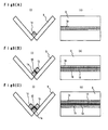
- the top face forming is carried out, for example, by setting a sintered main body in a molding frame for top face forming of spacers. This step is specifically described with reference to Fig. 4 and Fig. 5.
- Fig. 4 is a schematic view of a molding frame for top face forming of spacers
- Fig. 5 is a cross-sectional schematic view showing a state in which a sintered body with spacers according to the present invention is set in the molding frame.
- the molding frame 7 for top face forming is constituted by wall members 7a and 7b each having an L-shaped cross-section connected by a hinge 7c.
- Mold-separation papers 8 are attached to inner faces of the wall members 7a and 7b.
- spacers 3 of a sintered body 1 with spacers becomes easily separated from the molding frame, which can prevent e.g. deformation or damage at the time of separation, such being preferred.
- the wall members 7a and 7b may have inner faces made of materials excellent in mold-separation characteristic such as a fluororesin.
- Sintered-body-supporting members 14 are preferably provided on inner faces of the wall members 7a and 7b, for fixing a sintered main body 2 substantially at the center of the molding frame.
- the sintered-body-supporting members 14 may be ones having elasticity such as springs or spongies.
- Top face forming of spacers 3 is carried out in the following manner. First of all, a sintered main body 2 applied with spacers 3 is placed along inner faces of the wall member 7a. Then, another wall member 7 b is swung around a hinge 7c to make the molding frame 7 into square column shape and fixed by a catch (not shown). At this time, the pasty spacers 3 applied on side faces of the sintered main body 2 are pressed by the wall members 7a and 7b, and the sintered main body 2 is fixed in a state that top faces of the spacers are along inner faces of rectangular shape (square shape in the Figure) of the molding frame 7. Top faces of the spacers 3 formed on each of four side faces of the sintered main body 2, are formed to share a common plane by the wall member 7a or 7b, so that an outer shape defined by top faces is corrected to be a rectangular shape.
- the pasty spacers 3 are dried to be solidified. Accordingly, the spacers are solidified as they are molded so that the top faces fit to side faces of the square column having an accurate rectangular cross-section, and thus, an outer shape defined by spacer top faces of the sintered body with spacers, becomes an accurate rectangular solid or square column.
- a sintered body 1 with spacers according to the present invention is completed. Thereafter, the wall member 7b is opened to take out the sintered body 1 with spacers from the molding frame 7 for top face forming. At this time, the sintered body 1 with spacers can be easily taken out by the mold-separation paper 8.
- Figs 6(A) to 6(C) are schematic views sequentially showing the bonding method of the sintered bodies with spacers according to the present invention, wherein (i) and (ii) of Figs. 6(A) to 6(C) are side views and top views respectively.
- a sintered body 1a with spacers is placed on a bonding table 9 formed to have a V-shaped cross-section (crossing angle is 90°).
- the length of the bonding table 9 is formed to have the same length as that of the sintered body with spacers.
- the sintered body 1a with spacers is preferably positioned so that its central position in the longitudinal direction is aligned (centered) to the central position of the bonding table 9 in its longitudinal direction. Subsequently, as shown in Fig.
- another sintered body 1b with spacers is placed on the bonding table 9 so as to be adjacent to the sintered body 1a with spacers placed earlier, and the sintered body 1b with spacers is bonded to the sintered body 1a with spacers via a bonding agent 10.
- the bonding agent 10 one produced by adding an inorganic binder, an organic binder, inorganic particles or inorganic fibers into a solvent such as an alcohol or water and mixing and kneading them, is preferably employed.
- a sintered body 1c with spacers is bonded to another side face of the sintered body 1a with spacers. At this time, they are bonded so that their central positions in the longitudinal directions are aligned.
- a bonded body (refer to Fig. 7) of sintered bodies with spacers is formed.
- side faces of each sintered body are provided with spacers accurately formed so that planes defined by top faces of the spacers form a virtual square column. Accordingly, when the sintered bodies are piled up as they are aligned to one another, they are piled up in a state that the top faces of the spacers of adjacently bonded sintered bodies are contact with each other.
- the sintered bodies with spacers can be piled up and bonded as they are arranged in parallel in the same manner as in piling up square columns.
- sintered bodies having all four side faces provided with spacers are employed.
- side faces to which no sintered body is adjacent are not necessarily provided with spacers.
- Fig. 7 shows an end face of a bonded body formed by the bonding method of sintered bodies with spacers according to the present invention.
- a bonded body 11 is formed by bonding a sufficient number of sintered bodies 1 and 1a to constitute the shape (dotted line) of a honeycomb filter being a final product.
- 12 pieces of standard sintered bodies 1 and 4 pieces of corner small sintered bodies 1a are bonded as a combination.
- the sintered bodies 1 and 1a instead of using the V-shaped bonding table 9 of Fig. 6, the sintered bodies 1 and 1a are combined and bonded by using a bonding table of proper shape.
- the sintered bodies 1 and 1a each has spacers 3 provided on side faces and the external shape defined by the top faces of the spacers is rectangular as described above, and thus, adjacent sintered bodies 1 with spacers are bonded as they are parallel, aligned in vertical and lateral directions and oriented in the same direction.
- adjacent sintered bodies 1 with spacers are bonded without shift, and a bonded body having good dimension accuracy can be obtained. Accordingly, a large filter for e.g. trucks or buses can be formed by bonding a large number of sintered bodies 1 with spacers.
- the sintered bodies 1 with spacers are formed to have a unified shape of square column or rectangular solid, automation of bonding step of sintered bodies by a machine can be easily achieved. Thereafter, the bonded body 11 is subjected to machining steps such as cutting, grinding or polishing into cylindrical shape as shown in the dotted line of Fig. 7.
- Fig. 8 shows a ceramic honeycomb filter 12 produced by such machining steps, which is a large-sized filter to be employed as a DPF for cleaning exhaust gas of e.g. vehicles.
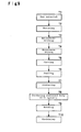
- Fig. 9 is a flow chart showing the process for producing a ceramic honeycomb filter.
- a raw material consisting of e.g. a ceramic powder such as a Si powder, a pore-forming agent and an auxiliary agent, is prepared.
- the raw material is mixed and kneaded into a clay state.
- the kneaded raw material is extrusion-molded.
- a molded body having through holes is produced.
- the molded body formed by the extrusion-molding is subjected to a microwave drying. This drying may be carried out by e.g. hot air or induction heating.
- the dried molded body is cut into a predetermined size.
- the sealing is to seal the through holes at the ends of the molded body into hound's tooth pattern as described in Fig. 1.
- the step may be carried out after sintering the molded body, after producing a sintered body with spacers or after producing a bonded body (refer to Fig. 7) depending on e.g. the material of the sealing member.
- the molded body is sintered.
- a sintered main body having substantially square column shape is formed.
- the sintered main body has non-flat warped surfaces as described above.
- a sintered body with spacers is produced according to the process shown in Fig. 2.
- a plurality of sintered bodies with spacers are bonded as shown in Fig. 6 or Fig. 7.
- the bonded body is cut into a cylindrical shape, and its surface is ground to form a ceramic honeycomb filter.
- the present invention can be applied to a case of forming a ceramic honeycomb filter to be used for buses or trucks by bonding a plurality of sintered bodies.
Landscapes
- Engineering & Computer Science (AREA)
- Chemical & Material Sciences (AREA)
- Physics & Mathematics (AREA)
- Geometry (AREA)
- Chemical Kinetics & Catalysis (AREA)
- Combustion & Propulsion (AREA)
- Mechanical Engineering (AREA)
- General Engineering & Computer Science (AREA)
- Filtering Materials (AREA)
- Filtering Of Dispersed Particles In Gases (AREA)
- Ceramic Products (AREA)
Applications Claiming Priority (2)
| Application Number | Priority Date | Filing Date | Title |
|---|---|---|---|
| JP2005058939 | 2005-03-03 | ||
| PCT/JP2006/303995 WO2006093231A1 (fr) | 2005-03-03 | 2006-03-02 | Corps fritte avec entretoises et son procede de production et de jonction |
Publications (1)
| Publication Number | Publication Date |
|---|---|
| EP1854773A1 true EP1854773A1 (fr) | 2007-11-14 |
Family
ID=36941260
Family Applications (1)
| Application Number | Title | Priority Date | Filing Date |
|---|---|---|---|
| EP06715104A Withdrawn EP1854773A1 (fr) | 2005-03-03 | 2006-03-02 | Corps fritte avec entretoises et son procede de production et de jonction |
Country Status (4)
| Country | Link |
|---|---|
| US (1) | US20080014404A1 (fr) |
| EP (1) | EP1854773A1 (fr) |
| JP (1) | JPWO2006093231A1 (fr) |
| WO (1) | WO2006093231A1 (fr) |
Cited By (5)
| Publication number | Priority date | Publication date | Assignee | Title |
|---|---|---|---|---|
| US7455710B2 (en) * | 2003-03-19 | 2008-11-25 | Ngk Insulators, Ltd. | Honeycomb structure and method of manufacturing the same |
| EP2080548A1 (fr) * | 2008-01-17 | 2009-07-22 | Ngk Insulators, Ltd. | Segment en nid d'abeille doté d'un espaceur et structure en nid d'abeille |
| WO2008137626A3 (fr) * | 2007-05-04 | 2009-09-24 | Dow Global Technologies Inc. | Éléments de filtre en nid d'abeilles améliorés |
| US8349432B2 (en) | 2008-03-24 | 2013-01-08 | Ibiden Co., Ltd. | Honeycomb structure and method for manufacturing honeycomb structure |
| WO2014003829A1 (fr) * | 2012-06-28 | 2014-01-03 | Dow Global Technologies Llc | Procédé de liaison de réseaux de filtre de céramique |
Families Citing this family (6)
| Publication number | Priority date | Publication date | Assignee | Title |
|---|---|---|---|---|
| EP1826517B1 (fr) * | 2006-02-28 | 2008-08-13 | Ibiden Co., Ltd. | Support de séchage, procédé de séchage d'un corps moulé en nid d'abeilles, et procédé pour la fabrication d'un corps à structure en nid d'abeilles |
| WO2008155856A1 (fr) | 2007-06-21 | 2008-12-24 | Ibiden Co., Ltd. | Structure en nid d'abeille et son procédé de production |
| JP5430867B2 (ja) * | 2007-06-21 | 2014-03-05 | イビデン株式会社 | ハニカム構造体、及び、ハニカム構造体の製造方法 |
| JP5767504B2 (ja) * | 2010-04-27 | 2015-08-19 | イビデン株式会社 | ハニカム構造体の製造方法 |
| JP2016079067A (ja) * | 2014-10-17 | 2016-05-16 | イビデン株式会社 | セラミック構造体並びにその製造方法及び装置 |
| CN118526838B (zh) * | 2024-07-11 | 2025-10-28 | 浙江省浦江宏达有限公司 | 一种流体过滤机构及其制备方法 |
Family Cites Families (4)
| Publication number | Priority date | Publication date | Assignee | Title |
|---|---|---|---|---|
| JPH0615138A (ja) * | 1992-07-06 | 1994-01-25 | Babcock Hitachi Kk | 触媒ブロック |
| JPH07213865A (ja) * | 1994-02-03 | 1995-08-15 | Babcock Hitachi Kk | 触媒ユニット |
| JP2000237601A (ja) * | 1999-02-16 | 2000-09-05 | Babcock Hitachi Kk | 触媒ユニットおよび触媒ブロック構造体 |
| JP4368050B2 (ja) * | 2000-09-27 | 2009-11-18 | イビデン株式会社 | セラミック構造体の製造方法 |
-
2006
- 2006-03-02 WO PCT/JP2006/303995 patent/WO2006093231A1/fr not_active Ceased
- 2006-03-02 JP JP2007506006A patent/JPWO2006093231A1/ja active Pending
- 2006-03-02 EP EP06715104A patent/EP1854773A1/fr not_active Withdrawn
-
2007
- 2007-08-24 US US11/844,378 patent/US20080014404A1/en not_active Abandoned
Non-Patent Citations (1)
| Title |
|---|
| See references of WO2006093231A1 * |
Cited By (6)
| Publication number | Priority date | Publication date | Assignee | Title |
|---|---|---|---|---|
| US7455710B2 (en) * | 2003-03-19 | 2008-11-25 | Ngk Insulators, Ltd. | Honeycomb structure and method of manufacturing the same |
| WO2008137626A3 (fr) * | 2007-05-04 | 2009-09-24 | Dow Global Technologies Inc. | Éléments de filtre en nid d'abeilles améliorés |
| EP2080548A1 (fr) * | 2008-01-17 | 2009-07-22 | Ngk Insulators, Ltd. | Segment en nid d'abeille doté d'un espaceur et structure en nid d'abeille |
| US8202602B2 (en) | 2008-01-17 | 2012-06-19 | Ngk Insulators, Ltd. | Honeycomb segment with spacer and honeycomb structure |
| US8349432B2 (en) | 2008-03-24 | 2013-01-08 | Ibiden Co., Ltd. | Honeycomb structure and method for manufacturing honeycomb structure |
| WO2014003829A1 (fr) * | 2012-06-28 | 2014-01-03 | Dow Global Technologies Llc | Procédé de liaison de réseaux de filtre de céramique |
Also Published As
| Publication number | Publication date |
|---|---|
| JPWO2006093231A1 (ja) | 2008-08-07 |
| US20080014404A1 (en) | 2008-01-17 |
| WO2006093231A1 (fr) | 2006-09-08 |
Similar Documents
| Publication | Publication Date | Title |
|---|---|---|
| US20080014404A1 (en) | Sintered body with spacers, and production method and bonding method for the same | |
| US7169203B2 (en) | Honeycomb structure | |
| KR100867292B1 (ko) | 세라믹 허니콤 구조체 | |
| EP2130574B1 (fr) | Filtre en nid d'abeilles | |
| EP2484504B1 (fr) | Méthode d'une fabrication d'une structure en nid d'abeilles | |
| EP2147905B1 (fr) | Procédé de production d'un corps lié de segments en nid d'abeille | |
| EP2116348B1 (fr) | Procédé permettant de fabriquer une structure à nid d'abeilles d'étanchéisation | |
| JP2002102627A (ja) | セラミック構造体及びその製造方法 | |
| WO2009118813A1 (fr) | Structure en nid d'abeille et son procédé de production | |
| KR20100021466A (ko) | 허니컴 세그먼트 성형용 다이와, 허니컴 구조체의 제조 방법 | |
| EP1726800B2 (fr) | Corps à structure en nids d'abeille | |
| EP2080548A1 (fr) | Segment en nid d'abeille doté d'un espaceur et structure en nid d'abeille | |
| CN108331642B (zh) | 蜂窝结构体 | |
| JP2009256187A (ja) | ハニカム構造体及びハニカム構造体の製造方法 | |
| JP4408203B2 (ja) | ハニカム構造体の製造方法 | |
| US9333683B2 (en) | Honeycomb structure and method for manufacturing the same | |
| EP1790408B1 (fr) | Structure en nid d'abeille | |
| JP2004075522A (ja) | セラミックハニカム構造体 | |
| US7438966B2 (en) | Honeycomb segment and honeycomb structure using the honeycomb segment | |
| JP6068219B2 (ja) | ハニカムフィルタ | |
| KR101403157B1 (ko) | 세라믹 허니컴 구조체의 제조방법 | |
| KR101265820B1 (ko) | 탄화규소질 허니컴 세그먼트용 접합재 및 이를 이용한허니컴 구조체 | |
| KR20090048241A (ko) | 탄화규소 필터의 제조방법 | |
| JPH01141732A (ja) | ハニカム状成形体の端面封止方法 |
Legal Events
| Date | Code | Title | Description |
|---|---|---|---|
| PUAI | Public reference made under article 153(3) epc to a published international application that has entered the european phase |
Free format text: ORIGINAL CODE: 0009012 |
|
| 17P | Request for examination filed |
Effective date: 20070830 |
|
| AK | Designated contracting states |
Kind code of ref document: A1 Designated state(s): DE FR GB NL PL |
|
| DAX | Request for extension of the european patent (deleted) | ||
| RBV | Designated contracting states (corrected) |
Designated state(s): DE FR GB NL PL |
|
| STAA | Information on the status of an ep patent application or granted ep patent |
Free format text: STATUS: THE APPLICATION IS DEEMED TO BE WITHDRAWN |
|
| 18D | Application deemed to be withdrawn |
Effective date: 20091111 |