EP1854909A2 - Structure de revêtement et son procédé de réalisation - Google Patents
Structure de revêtement et son procédé de réalisation Download PDFInfo
- Publication number
- EP1854909A2 EP1854909A2 EP20070107945 EP07107945A EP1854909A2 EP 1854909 A2 EP1854909 A2 EP 1854909A2 EP 20070107945 EP20070107945 EP 20070107945 EP 07107945 A EP07107945 A EP 07107945A EP 1854909 A2 EP1854909 A2 EP 1854909A2
- Authority
- EP
- European Patent Office
- Prior art keywords
- film
- coating structure
- nip
- forming
- fluorine
- Prior art date
- Legal status (The legal status is an assumption and is not a legal conclusion. Google has not performed a legal analysis and makes no representation as to the accuracy of the status listed.)
- Granted
Links
- 239000011248 coating agent Substances 0.000 title claims abstract description 117
- 238000000576 coating method Methods 0.000 title claims abstract description 117
- 238000000034 method Methods 0.000 title claims description 45
- YCKRFDGAMUMZLT-UHFFFAOYSA-N Fluorine atom Chemical compound [F] YCKRFDGAMUMZLT-UHFFFAOYSA-N 0.000 claims abstract description 97
- 229910052731 fluorine Inorganic materials 0.000 claims abstract description 97
- 239000011737 fluorine Substances 0.000 claims abstract description 97
- 239000002184 metal Substances 0.000 claims abstract description 87
- 229910052751 metal Inorganic materials 0.000 claims abstract description 87
- 239000000446 fuel Substances 0.000 claims abstract description 58
- 238000009499 grossing Methods 0.000 claims abstract description 46
- 238000002347 injection Methods 0.000 claims abstract description 41
- 239000007924 injection Substances 0.000 claims abstract description 41
- 239000000243 solution Substances 0.000 claims abstract description 20
- 238000001035 drying Methods 0.000 claims abstract description 5
- 239000002131 composite material Substances 0.000 claims description 84
- 230000003746 surface roughness Effects 0.000 claims description 51
- 229920001343 polytetrafluoroethylene Polymers 0.000 claims description 44
- 239000004810 polytetrafluoroethylene Substances 0.000 claims description 44
- 239000002245 particle Substances 0.000 claims description 22
- 229910052799 carbon Inorganic materials 0.000 claims description 16
- OKTJSMMVPCPJKN-UHFFFAOYSA-N Carbon Chemical compound [C] OKTJSMMVPCPJKN-UHFFFAOYSA-N 0.000 claims description 14
- 238000004544 sputter deposition Methods 0.000 claims description 6
- 238000007772 electroless plating Methods 0.000 claims description 5
- 238000007733 ion plating Methods 0.000 claims description 3
- 238000005268 plasma chemical vapour deposition Methods 0.000 claims description 3
- 239000000463 material Substances 0.000 description 18
- 238000010438 heat treatment Methods 0.000 description 15
- PXHVJJICTQNCMI-UHFFFAOYSA-N nickel Substances [Ni] PXHVJJICTQNCMI-UHFFFAOYSA-N 0.000 description 15
- XLYOFNOQVPJJNP-UHFFFAOYSA-N water Substances O XLYOFNOQVPJJNP-UHFFFAOYSA-N 0.000 description 12
- XKRFYHLGVUSROY-UHFFFAOYSA-N Argon Chemical compound [Ar] XKRFYHLGVUSROY-UHFFFAOYSA-N 0.000 description 8
- 238000010586 diagram Methods 0.000 description 8
- 229910052786 argon Inorganic materials 0.000 description 5
- 239000007789 gas Substances 0.000 description 5
- VEXZGXHMUGYJMC-UHFFFAOYSA-N Hydrochloric acid Chemical compound Cl VEXZGXHMUGYJMC-UHFFFAOYSA-N 0.000 description 4
- 230000000052 comparative effect Effects 0.000 description 4
- 230000004048 modification Effects 0.000 description 4
- 238000012986 modification Methods 0.000 description 4
- QTBSBXVTEAMEQO-UHFFFAOYSA-N Acetic acid Chemical compound CC(O)=O QTBSBXVTEAMEQO-UHFFFAOYSA-N 0.000 description 3
- 239000007864 aqueous solution Substances 0.000 description 3
- 230000006866 deterioration Effects 0.000 description 3
- 230000000694 effects Effects 0.000 description 3
- -1 polytetrafluoroethylene Polymers 0.000 description 3
- 239000004215 Carbon black (E152) Substances 0.000 description 2
- VYZAMTAEIAYCRO-UHFFFAOYSA-N Chromium Chemical compound [Cr] VYZAMTAEIAYCRO-UHFFFAOYSA-N 0.000 description 2
- QAOWNCQODCNURD-UHFFFAOYSA-N Sulfuric acid Chemical compound OS(O)(=O)=O QAOWNCQODCNURD-UHFFFAOYSA-N 0.000 description 2
- 230000003373 anti-fouling effect Effects 0.000 description 2
- 229910000963 austenitic stainless steel Inorganic materials 0.000 description 2
- 238000009713 electroplating Methods 0.000 description 2
- 229930195733 hydrocarbon Natural products 0.000 description 2
- 150000002430 hydrocarbons Chemical class 0.000 description 2
- 239000000126 substance Substances 0.000 description 2
- 229910052721 tungsten Inorganic materials 0.000 description 2
- 229910021586 Nickel(II) chloride Inorganic materials 0.000 description 1
- BRZANEXCSZCZCI-UHFFFAOYSA-N Nifenazone Chemical compound O=C1N(C=2C=CC=CC=2)N(C)C(C)=C1NC(=O)C1=CC=CN=C1 BRZANEXCSZCZCI-UHFFFAOYSA-N 0.000 description 1
- RTAQQCXQSZGOHL-UHFFFAOYSA-N Titanium Chemical compound [Ti] RTAQQCXQSZGOHL-UHFFFAOYSA-N 0.000 description 1
- 238000005299 abrasion Methods 0.000 description 1
- 150000001343 alkyl silanes Chemical class 0.000 description 1
- 239000002551 biofuel Substances 0.000 description 1
- 150000001768 cations Chemical class 0.000 description 1
- 238000004140 cleaning Methods 0.000 description 1
- 238000004891 communication Methods 0.000 description 1
- 238000010411 cooking Methods 0.000 description 1
- 230000003247 decreasing effect Effects 0.000 description 1
- 230000005611 electricity Effects 0.000 description 1
- 238000005530 etching Methods 0.000 description 1
- 239000007788 liquid Substances 0.000 description 1
- 238000005461 lubrication Methods 0.000 description 1
- 238000004519 manufacturing process Methods 0.000 description 1
- 239000007769 metal material Substances 0.000 description 1
- QMMRZOWCJAIUJA-UHFFFAOYSA-L nickel dichloride Chemical compound Cl[Ni]Cl QMMRZOWCJAIUJA-UHFFFAOYSA-L 0.000 description 1
- 230000002093 peripheral effect Effects 0.000 description 1
- 229910052710 silicon Inorganic materials 0.000 description 1
- 239000010703 silicon Substances 0.000 description 1
- 239000007787 solid Substances 0.000 description 1
- 239000004094 surface-active agent Substances 0.000 description 1
- WFKWXMTUELFFGS-UHFFFAOYSA-N tungsten Chemical compound [W] WFKWXMTUELFFGS-UHFFFAOYSA-N 0.000 description 1
- 239000010937 tungsten Substances 0.000 description 1
- UONOETXJSWQNOL-UHFFFAOYSA-N tungsten carbide Chemical compound [W+]#[C-] UONOETXJSWQNOL-UHFFFAOYSA-N 0.000 description 1
Images


Classifications
-
- C—CHEMISTRY; METALLURGY
- C23—COATING METALLIC MATERIAL; COATING MATERIAL WITH METALLIC MATERIAL; CHEMICAL SURFACE TREATMENT; DIFFUSION TREATMENT OF METALLIC MATERIAL; COATING BY VACUUM EVAPORATION, BY SPUTTERING, BY ION IMPLANTATION OR BY CHEMICAL VAPOUR DEPOSITION, IN GENERAL; INHIBITING CORROSION OF METALLIC MATERIAL OR INCRUSTATION IN GENERAL
- C23C—COATING METALLIC MATERIAL; COATING MATERIAL WITH METALLIC MATERIAL; SURFACE TREATMENT OF METALLIC MATERIAL BY DIFFUSION INTO THE SURFACE, BY CHEMICAL CONVERSION OR SUBSTITUTION; COATING BY VACUUM EVAPORATION, BY SPUTTERING, BY ION IMPLANTATION OR BY CHEMICAL VAPOUR DEPOSITION, IN GENERAL
- C23C28/00—Coating for obtaining at least two superposed coatings either by methods not provided for in a single one of groups C23C2/00 - C23C26/00 or by combinations of methods provided for in subclasses C23C and C25C or C25D
-
- C—CHEMISTRY; METALLURGY
- C23—COATING METALLIC MATERIAL; COATING MATERIAL WITH METALLIC MATERIAL; CHEMICAL SURFACE TREATMENT; DIFFUSION TREATMENT OF METALLIC MATERIAL; COATING BY VACUUM EVAPORATION, BY SPUTTERING, BY ION IMPLANTATION OR BY CHEMICAL VAPOUR DEPOSITION, IN GENERAL; INHIBITING CORROSION OF METALLIC MATERIAL OR INCRUSTATION IN GENERAL
- C23C—COATING METALLIC MATERIAL; COATING MATERIAL WITH METALLIC MATERIAL; SURFACE TREATMENT OF METALLIC MATERIAL BY DIFFUSION INTO THE SURFACE, BY CHEMICAL CONVERSION OR SUBSTITUTION; COATING BY VACUUM EVAPORATION, BY SPUTTERING, BY ION IMPLANTATION OR BY CHEMICAL VAPOUR DEPOSITION, IN GENERAL
- C23C18/00—Chemical coating by decomposition of either liquid compounds or solutions of the coating forming compounds, without leaving reaction products of surface material in the coating; Contact plating
- C23C18/16—Chemical coating by decomposition of either liquid compounds or solutions of the coating forming compounds, without leaving reaction products of surface material in the coating; Contact plating by reduction or substitution, e.g. electroless plating
- C23C18/1601—Process or apparatus
- C23C18/1619—Apparatus for electroless plating
- C23C18/1628—Specific elements or parts of the apparatus
-
- C—CHEMISTRY; METALLURGY
- C23—COATING METALLIC MATERIAL; COATING MATERIAL WITH METALLIC MATERIAL; CHEMICAL SURFACE TREATMENT; DIFFUSION TREATMENT OF METALLIC MATERIAL; COATING BY VACUUM EVAPORATION, BY SPUTTERING, BY ION IMPLANTATION OR BY CHEMICAL VAPOUR DEPOSITION, IN GENERAL; INHIBITING CORROSION OF METALLIC MATERIAL OR INCRUSTATION IN GENERAL
- C23C—COATING METALLIC MATERIAL; COATING MATERIAL WITH METALLIC MATERIAL; SURFACE TREATMENT OF METALLIC MATERIAL BY DIFFUSION INTO THE SURFACE, BY CHEMICAL CONVERSION OR SUBSTITUTION; COATING BY VACUUM EVAPORATION, BY SPUTTERING, BY ION IMPLANTATION OR BY CHEMICAL VAPOUR DEPOSITION, IN GENERAL
- C23C18/00—Chemical coating by decomposition of either liquid compounds or solutions of the coating forming compounds, without leaving reaction products of surface material in the coating; Contact plating
- C23C18/16—Chemical coating by decomposition of either liquid compounds or solutions of the coating forming compounds, without leaving reaction products of surface material in the coating; Contact plating by reduction or substitution, e.g. electroless plating
- C23C18/1601—Process or apparatus
- C23C18/1633—Process of electroless plating
- C23C18/1646—Characteristics of the product obtained
- C23C18/165—Multilayered product
- C23C18/1651—Two or more layers only obtained by electroless plating
-
- C—CHEMISTRY; METALLURGY
- C23—COATING METALLIC MATERIAL; COATING MATERIAL WITH METALLIC MATERIAL; CHEMICAL SURFACE TREATMENT; DIFFUSION TREATMENT OF METALLIC MATERIAL; COATING BY VACUUM EVAPORATION, BY SPUTTERING, BY ION IMPLANTATION OR BY CHEMICAL VAPOUR DEPOSITION, IN GENERAL; INHIBITING CORROSION OF METALLIC MATERIAL OR INCRUSTATION IN GENERAL
- C23C—COATING METALLIC MATERIAL; COATING MATERIAL WITH METALLIC MATERIAL; SURFACE TREATMENT OF METALLIC MATERIAL BY DIFFUSION INTO THE SURFACE, BY CHEMICAL CONVERSION OR SUBSTITUTION; COATING BY VACUUM EVAPORATION, BY SPUTTERING, BY ION IMPLANTATION OR BY CHEMICAL VAPOUR DEPOSITION, IN GENERAL
- C23C18/00—Chemical coating by decomposition of either liquid compounds or solutions of the coating forming compounds, without leaving reaction products of surface material in the coating; Contact plating
- C23C18/16—Chemical coating by decomposition of either liquid compounds or solutions of the coating forming compounds, without leaving reaction products of surface material in the coating; Contact plating by reduction or substitution, e.g. electroless plating
- C23C18/1601—Process or apparatus
- C23C18/1633—Process of electroless plating
- C23C18/1655—Process features
- C23C18/1662—Use of incorporated material in the solution or dispersion, e.g. particles, whiskers, wires
-
- C—CHEMISTRY; METALLURGY
- C23—COATING METALLIC MATERIAL; COATING MATERIAL WITH METALLIC MATERIAL; CHEMICAL SURFACE TREATMENT; DIFFUSION TREATMENT OF METALLIC MATERIAL; COATING BY VACUUM EVAPORATION, BY SPUTTERING, BY ION IMPLANTATION OR BY CHEMICAL VAPOUR DEPOSITION, IN GENERAL; INHIBITING CORROSION OF METALLIC MATERIAL OR INCRUSTATION IN GENERAL
- C23C—COATING METALLIC MATERIAL; COATING MATERIAL WITH METALLIC MATERIAL; SURFACE TREATMENT OF METALLIC MATERIAL BY DIFFUSION INTO THE SURFACE, BY CHEMICAL CONVERSION OR SUBSTITUTION; COATING BY VACUUM EVAPORATION, BY SPUTTERING, BY ION IMPLANTATION OR BY CHEMICAL VAPOUR DEPOSITION, IN GENERAL
- C23C18/00—Chemical coating by decomposition of either liquid compounds or solutions of the coating forming compounds, without leaving reaction products of surface material in the coating; Contact plating
- C23C18/16—Chemical coating by decomposition of either liquid compounds or solutions of the coating forming compounds, without leaving reaction products of surface material in the coating; Contact plating by reduction or substitution, e.g. electroless plating
- C23C18/31—Coating with metals
- C23C18/32—Coating with nickel, cobalt or mixtures thereof with phosphorus or boron
-
- C—CHEMISTRY; METALLURGY
- C23—COATING METALLIC MATERIAL; COATING MATERIAL WITH METALLIC MATERIAL; CHEMICAL SURFACE TREATMENT; DIFFUSION TREATMENT OF METALLIC MATERIAL; COATING BY VACUUM EVAPORATION, BY SPUTTERING, BY ION IMPLANTATION OR BY CHEMICAL VAPOUR DEPOSITION, IN GENERAL; INHIBITING CORROSION OF METALLIC MATERIAL OR INCRUSTATION IN GENERAL
- C23C—COATING METALLIC MATERIAL; COATING MATERIAL WITH METALLIC MATERIAL; SURFACE TREATMENT OF METALLIC MATERIAL BY DIFFUSION INTO THE SURFACE, BY CHEMICAL CONVERSION OR SUBSTITUTION; COATING BY VACUUM EVAPORATION, BY SPUTTERING, BY ION IMPLANTATION OR BY CHEMICAL VAPOUR DEPOSITION, IN GENERAL
- C23C28/00—Coating for obtaining at least two superposed coatings either by methods not provided for in a single one of groups C23C2/00 - C23C26/00 or by combinations of methods provided for in subclasses C23C and C25C or C25D
- C23C28/30—Coatings combining at least one metallic layer and at least one inorganic non-metallic layer
- C23C28/32—Coatings combining at least one metallic layer and at least one inorganic non-metallic layer including at least one pure metallic layer
- C23C28/321—Coatings combining at least one metallic layer and at least one inorganic non-metallic layer including at least one pure metallic layer with at least one metal alloy layer
-
- C—CHEMISTRY; METALLURGY
- C23—COATING METALLIC MATERIAL; COATING MATERIAL WITH METALLIC MATERIAL; CHEMICAL SURFACE TREATMENT; DIFFUSION TREATMENT OF METALLIC MATERIAL; COATING BY VACUUM EVAPORATION, BY SPUTTERING, BY ION IMPLANTATION OR BY CHEMICAL VAPOUR DEPOSITION, IN GENERAL; INHIBITING CORROSION OF METALLIC MATERIAL OR INCRUSTATION IN GENERAL
- C23C—COATING METALLIC MATERIAL; COATING MATERIAL WITH METALLIC MATERIAL; SURFACE TREATMENT OF METALLIC MATERIAL BY DIFFUSION INTO THE SURFACE, BY CHEMICAL CONVERSION OR SUBSTITUTION; COATING BY VACUUM EVAPORATION, BY SPUTTERING, BY ION IMPLANTATION OR BY CHEMICAL VAPOUR DEPOSITION, IN GENERAL
- C23C28/00—Coating for obtaining at least two superposed coatings either by methods not provided for in a single one of groups C23C2/00 - C23C26/00 or by combinations of methods provided for in subclasses C23C and C25C or C25D
- C23C28/30—Coatings combining at least one metallic layer and at least one inorganic non-metallic layer
- C23C28/32—Coatings combining at least one metallic layer and at least one inorganic non-metallic layer including at least one pure metallic layer
- C23C28/322—Coatings combining at least one metallic layer and at least one inorganic non-metallic layer including at least one pure metallic layer only coatings of metal elements only
-
- C—CHEMISTRY; METALLURGY
- C23—COATING METALLIC MATERIAL; COATING MATERIAL WITH METALLIC MATERIAL; CHEMICAL SURFACE TREATMENT; DIFFUSION TREATMENT OF METALLIC MATERIAL; COATING BY VACUUM EVAPORATION, BY SPUTTERING, BY ION IMPLANTATION OR BY CHEMICAL VAPOUR DEPOSITION, IN GENERAL; INHIBITING CORROSION OF METALLIC MATERIAL OR INCRUSTATION IN GENERAL
- C23C—COATING METALLIC MATERIAL; COATING MATERIAL WITH METALLIC MATERIAL; SURFACE TREATMENT OF METALLIC MATERIAL BY DIFFUSION INTO THE SURFACE, BY CHEMICAL CONVERSION OR SUBSTITUTION; COATING BY VACUUM EVAPORATION, BY SPUTTERING, BY ION IMPLANTATION OR BY CHEMICAL VAPOUR DEPOSITION, IN GENERAL
- C23C28/00—Coating for obtaining at least two superposed coatings either by methods not provided for in a single one of groups C23C2/00 - C23C26/00 or by combinations of methods provided for in subclasses C23C and C25C or C25D
- C23C28/30—Coatings combining at least one metallic layer and at least one inorganic non-metallic layer
- C23C28/34—Coatings combining at least one metallic layer and at least one inorganic non-metallic layer including at least one inorganic non-metallic material layer, e.g. metal carbide, nitride, boride, silicide layer and their mixtures, enamels, phosphates and sulphates
- C23C28/343—Coatings combining at least one metallic layer and at least one inorganic non-metallic layer including at least one inorganic non-metallic material layer, e.g. metal carbide, nitride, boride, silicide layer and their mixtures, enamels, phosphates and sulphates with at least one DLC or an amorphous carbon based layer, the layer being doped or not
-
- F—MECHANICAL ENGINEERING; LIGHTING; HEATING; WEAPONS; BLASTING
- F02—COMBUSTION ENGINES; HOT-GAS OR COMBUSTION-PRODUCT ENGINE PLANTS
- F02M—SUPPLYING COMBUSTION ENGINES IN GENERAL WITH COMBUSTIBLE MIXTURES OR CONSTITUENTS THEREOF
- F02M61/00—Fuel-injectors not provided for in groups F02M39/00 - F02M57/00 or F02M67/00
- F02M61/04—Fuel-injectors not provided for in groups F02M39/00 - F02M57/00 or F02M67/00 having valves, e.g. having a plurality of valves in series
- F02M61/10—Other injectors with elongated valve bodies, i.e. of needle-valve type
-
- F—MECHANICAL ENGINEERING; LIGHTING; HEATING; WEAPONS; BLASTING
- F02—COMBUSTION ENGINES; HOT-GAS OR COMBUSTION-PRODUCT ENGINE PLANTS
- F02M—SUPPLYING COMBUSTION ENGINES IN GENERAL WITH COMBUSTIBLE MIXTURES OR CONSTITUENTS THEREOF
- F02M61/00—Fuel-injectors not provided for in groups F02M39/00 - F02M57/00 or F02M67/00
- F02M61/16—Details not provided for in, or of interest apart from, the apparatus of groups F02M61/02 - F02M61/14
- F02M61/168—Assembling; Disassembling; Manufacturing; Adjusting
-
- F—MECHANICAL ENGINEERING; LIGHTING; HEATING; WEAPONS; BLASTING
- F02—COMBUSTION ENGINES; HOT-GAS OR COMBUSTION-PRODUCT ENGINE PLANTS
- F02M—SUPPLYING COMBUSTION ENGINES IN GENERAL WITH COMBUSTIBLE MIXTURES OR CONSTITUENTS THEREOF
- F02M2200/00—Details of fuel-injection apparatus, not otherwise provided for
- F02M2200/02—Fuel-injection apparatus having means for reducing wear
-
- F—MECHANICAL ENGINEERING; LIGHTING; HEATING; WEAPONS; BLASTING
- F02—COMBUSTION ENGINES; HOT-GAS OR COMBUSTION-PRODUCT ENGINE PLANTS
- F02M—SUPPLYING COMBUSTION ENGINES IN GENERAL WITH COMBUSTIBLE MIXTURES OR CONSTITUENTS THEREOF
- F02M2200/00—Details of fuel-injection apparatus, not otherwise provided for
- F02M2200/90—Selection of particular materials
- F02M2200/9038—Coatings
-
- F—MECHANICAL ENGINEERING; LIGHTING; HEATING; WEAPONS; BLASTING
- F02—COMBUSTION ENGINES; HOT-GAS OR COMBUSTION-PRODUCT ENGINE PLANTS
- F02M—SUPPLYING COMBUSTION ENGINES IN GENERAL WITH COMBUSTIBLE MIXTURES OR CONSTITUENTS THEREOF
- F02M2200/00—Details of fuel-injection apparatus, not otherwise provided for
- F02M2200/90—Selection of particular materials
- F02M2200/9046—Multi-layered materials
-
- Y—GENERAL TAGGING OF NEW TECHNOLOGICAL DEVELOPMENTS; GENERAL TAGGING OF CROSS-SECTIONAL TECHNOLOGIES SPANNING OVER SEVERAL SECTIONS OF THE IPC; TECHNICAL SUBJECTS COVERED BY FORMER USPC CROSS-REFERENCE ART COLLECTIONS [XRACs] AND DIGESTS
- Y10—TECHNICAL SUBJECTS COVERED BY FORMER USPC
- Y10T—TECHNICAL SUBJECTS COVERED BY FORMER US CLASSIFICATION
- Y10T428/00—Stock material or miscellaneous articles
- Y10T428/12—All metal or with adjacent metals
- Y10T428/12493—Composite; i.e., plural, adjacent, spatially distinct metal components [e.g., layers, joint, etc.]
- Y10T428/12535—Composite; i.e., plural, adjacent, spatially distinct metal components [e.g., layers, joint, etc.] with additional, spatially distinct nonmetal component
- Y10T428/12556—Organic component
- Y10T428/12569—Synthetic resin
-
- Y—GENERAL TAGGING OF NEW TECHNOLOGICAL DEVELOPMENTS; GENERAL TAGGING OF CROSS-SECTIONAL TECHNOLOGIES SPANNING OVER SEVERAL SECTIONS OF THE IPC; TECHNICAL SUBJECTS COVERED BY FORMER USPC CROSS-REFERENCE ART COLLECTIONS [XRACs] AND DIGESTS
- Y10—TECHNICAL SUBJECTS COVERED BY FORMER USPC
- Y10T—TECHNICAL SUBJECTS COVERED BY FORMER US CLASSIFICATION
- Y10T428/00—Stock material or miscellaneous articles
- Y10T428/12—All metal or with adjacent metals
- Y10T428/12493—Composite; i.e., plural, adjacent, spatially distinct metal components [e.g., layers, joint, etc.]
- Y10T428/12535—Composite; i.e., plural, adjacent, spatially distinct metal components [e.g., layers, joint, etc.] with additional, spatially distinct nonmetal component
- Y10T428/12583—Component contains compound of adjacent metal
-
- Y—GENERAL TAGGING OF NEW TECHNOLOGICAL DEVELOPMENTS; GENERAL TAGGING OF CROSS-SECTIONAL TECHNOLOGIES SPANNING OVER SEVERAL SECTIONS OF THE IPC; TECHNICAL SUBJECTS COVERED BY FORMER USPC CROSS-REFERENCE ART COLLECTIONS [XRACs] AND DIGESTS
- Y10—TECHNICAL SUBJECTS COVERED BY FORMER USPC
- Y10T—TECHNICAL SUBJECTS COVERED BY FORMER US CLASSIFICATION
- Y10T428/00—Stock material or miscellaneous articles
- Y10T428/24—Structurally defined web or sheet [e.g., overall dimension, etc.]
- Y10T428/24355—Continuous and nonuniform or irregular surface on layer or component [e.g., roofing, etc.]
- Y10T428/24372—Particulate matter
- Y10T428/24405—Polymer or resin [e.g., natural or synthetic rubber, etc.]
-
- Y—GENERAL TAGGING OF NEW TECHNOLOGICAL DEVELOPMENTS; GENERAL TAGGING OF CROSS-SECTIONAL TECHNOLOGIES SPANNING OVER SEVERAL SECTIONS OF THE IPC; TECHNICAL SUBJECTS COVERED BY FORMER USPC CROSS-REFERENCE ART COLLECTIONS [XRACs] AND DIGESTS
- Y10—TECHNICAL SUBJECTS COVERED BY FORMER USPC
- Y10T—TECHNICAL SUBJECTS COVERED BY FORMER US CLASSIFICATION
- Y10T428/00—Stock material or miscellaneous articles
- Y10T428/25—Web or sheet containing structurally defined element or component and including a second component containing structurally defined particles
- Y10T428/254—Polymeric or resinous material
-
- Y—GENERAL TAGGING OF NEW TECHNOLOGICAL DEVELOPMENTS; GENERAL TAGGING OF CROSS-SECTIONAL TECHNOLOGIES SPANNING OVER SEVERAL SECTIONS OF THE IPC; TECHNICAL SUBJECTS COVERED BY FORMER USPC CROSS-REFERENCE ART COLLECTIONS [XRACs] AND DIGESTS
- Y10—TECHNICAL SUBJECTS COVERED BY FORMER USPC
- Y10T—TECHNICAL SUBJECTS COVERED BY FORMER US CLASSIFICATION
- Y10T428/00—Stock material or miscellaneous articles
- Y10T428/26—Web or sheet containing structurally defined element or component, the element or component having a specified physical dimension
- Y10T428/263—Coating layer not in excess of 5 mils thick or equivalent
- Y10T428/264—Up to 3 mils
- Y10T428/265—1 mil or less
-
- Y—GENERAL TAGGING OF NEW TECHNOLOGICAL DEVELOPMENTS; GENERAL TAGGING OF CROSS-SECTIONAL TECHNOLOGIES SPANNING OVER SEVERAL SECTIONS OF THE IPC; TECHNICAL SUBJECTS COVERED BY FORMER USPC CROSS-REFERENCE ART COLLECTIONS [XRACs] AND DIGESTS
- Y10—TECHNICAL SUBJECTS COVERED BY FORMER USPC
- Y10T—TECHNICAL SUBJECTS COVERED BY FORMER US CLASSIFICATION
- Y10T428/00—Stock material or miscellaneous articles
- Y10T428/30—Self-sustaining carbon mass or layer with impregnant or other layer
-
- Y—GENERAL TAGGING OF NEW TECHNOLOGICAL DEVELOPMENTS; GENERAL TAGGING OF CROSS-SECTIONAL TECHNOLOGIES SPANNING OVER SEVERAL SECTIONS OF THE IPC; TECHNICAL SUBJECTS COVERED BY FORMER USPC CROSS-REFERENCE ART COLLECTIONS [XRACs] AND DIGESTS
- Y10—TECHNICAL SUBJECTS COVERED BY FORMER USPC
- Y10T—TECHNICAL SUBJECTS COVERED BY FORMER US CLASSIFICATION
- Y10T428/00—Stock material or miscellaneous articles
- Y10T428/31504—Composite [nonstructural laminate]
- Y10T428/3154—Of fluorinated addition polymer from unsaturated monomers
- Y10T428/31544—Addition polymer is perhalogenated
Definitions
- the present invention relates to a coating structure including a fluorine-based film on a metal member, and a method for forming the same.
- a coating structure including a fluorine-based film is used, for example.
- the coating structure can be used for a member which is heated and is required to have an antifouling property, e.g., a vehicle component such as a fuel injection nozzle as disclosed in JP-A-8-144893 , and a household product such as a flying pan and a cooking stove.
- a thickness of the fluorine-based film is typically very thin, e.g., a few dozens nm. Therefore, when the fluorine-based film is directly formed on the metal member having a large surface roughness, the fluorine-based film becomes uneven with a sink, and cannot provide a sufficient water-shedding property. Thus, when the fluorine-based film is formed on the metal member having the large surface roughness, the metal member is required to be smoothed in advance so that the surface roughness is within a nanometer range, for preventing the sink in the fluorine-based film.
- a coating structure can be formed on the metal member having the large surface roughness without a process of smoothing the surface of the metal member, while having the sufficient water-shedding property which is not reduced by heating.
- the fuel injection nozzle with the fluorine-based film In the fuel injection nozzle with the fluorine-based film, the nozzle is subjected to a high temperature due to a high-fuel injection pressure, and a fuel situation is changed due to a utilization of a biofuel. Therefore, the fuel injection nozzle has a problem that a large amount of foreign material, which is considered as a product generated from fuel, adheres to a needle of the fuel injection nozzle.
- the fuel injection nozzle includes a nozzle body having an injection hole for injecting fuel, and the needle which is housed in the nozzle body to be slidable.
- the fuel injection nozzle injects fuel by sliding the needle for opening the injection hole.
- the needle may be difficult to slide, and furthermore, the needle may adhere to the nozzle body and an engine may fail to start.
- the fuel injection nozzle is required to have a coating structure, which has a sufficient water-shedding property and can prevent the adherence of the foreign material.
- the coating structure may be used for a metal member having a large surface roughness.
- another object of the invention is to provide a method for forming a coating structure having a sufficient water-shedding property, on a metal member, regardless of surface roughness of the metal member.
- a coating structure for a metal member includes a surface-smoothing layer, formed on the metal member, for smoothing a surface of the metal member, and a fluorine-based film formed on the surface-smoothing layer.
- the fluorine-based film is not formed directly on the metal member, but formed on the surface-smoothing layer which is formed on the metal member. Therefore, the coating structure can have the sufficient water-shedding property which is not reduced by heating. Further, the coating structure may be used for a metal member having the large surface roughness.
- a method for forming a coating structure for a metal member includes a step of forming a surface-smoothing layer on a metal member to smooth a surface of the metal member, a step of applying a fluorine-containing solution on the surface-smoothing layer, and a step of drying the fluorine-containing solution to form a fluorine-based film.
- the fluorine-based film is not formed directly on the metal member, but formed on the surface-smoothing layer which is formed on the metal member. Therefore, the coating structure formed by the method can have the sufficient water-shedding property which is not reduced by heating, regardless of a surface roughness of the metal member.
- a coating structure 1 includes a surface-smoothing layer 11 and a fluorine-based film 12.
- the surface-smoothing layer 11 for smoothing a surface of a metal member 10 is formed on the metal member 10, and the fluorine-based film 12 is formed on the surface-smoothing layer 11.
- a NiP/PTFE composite film hereafter, composite film
- PTFE polytetrafluoroethylene
- the coating structure 1 can be used for the metal member 10 made of a various metal-based material.
- An example material for the metal member 10 is a Fe-based material.
- the coating structure 1 can provide a waterproof property (e.g., water-shedding property) effectively.
- an austenitic stainless steel (SUS304) consisting mainly of Fe is used.
- a surface roughness Rz(10) of the metal member 10 is about 2 ⁇ m, and the surface of the metal member 10 is uneven.
- Ni strike film 13 formed directly on the metal member 10, as an adhesion layer.
- NiP film 14 formed directly on the Ni strike film 13, as a ground layer.
- a preferred thickness of each of the Ni strike film 13 and the NiP film 14 is about in a range of 0.5 to 1.5 ⁇ m. When the thickness is under 0.5 ⁇ m, the adhesiveness of the composite film 11 may be not improved effectively. When the thickness is over 1.5 ⁇ m, a production cost of the coating structure 1 becomes high.
- the thickness of the Ni strike film 13 is 1 ⁇ m
- the thickness of the NiP film 14 is 1 ⁇ m, as an example.
- the Ni strike film 13 may be formed by an electroplating, and the NiP film 14 may be formed by an electroless plating, for example. In each case, the Ni strike film 13 and the NiP film 14 are formed with high accuracies.
- the composite film 11 is formed.
- the PTFE particles are dispersed in the NiP as a base material.
- a preferred particle size of the PTFE particles is about in a range of 0.2 to 1 ⁇ m. When the particle size is under 0.2 ⁇ m, the composite film 11 may not provide the water-shedding property effectively. When the particle size is over 1 ⁇ m, it may be difficult to disperse the PTFE particles uniformly.
- a preferred content rate of the PTFE particles in the composite film is about in a range of 7 to 9 wt%. When the content rate of the PTFE particles in the composite film is under 7 wt%, the water-shedding property of the composite film 11 may be reduced. When the content rate of PTFE particles in the composite film is over 9 wt%, a heat-resistance of the composite film 11 may be reduced.
- the composite film 11 may be formed by an electroless plating. In this case, the composite film 11 may be formed with a high accuracy.
- the composite film 11 may be formed by another method, such as an electroplating.
- a preferred thickness of the composite film 11 is about in a range of 5 to 20 ⁇ m.
- the composite film 11 may be difficult to be formed with the high accuracy on the metal member 10 having the large surface roughness.
- the thickness of the composite film 11 is over 20 ⁇ m, it may be difficult to control the thickness. Therefore, more preferred thickness of the composite film 11 is about in a range of 5 to 15 ⁇ m.
- a particle size of the PTFE particles is about in a range of 0.2 to 1 ⁇ m
- the content rate of the PTFE particles in the composite film is about in a range of 7 to 9 wt% (i.e., 22 to 26 vol%)
- a thickness of the composite film 11 is 10 ⁇ m, as an example.
- a preferred surface roughness Rz of a surface, on which the composite film 11 is formed i.e., a surface roughness Rz of a layer under the composite film 11, is not more than about 5 ⁇ m.
- the surface roughness Rz is over 5 ⁇ m, a sick may be occurred in the composite film 11, and the composite film 11 may be not formed with the high accuracy.
- the surface roughness Rz of the surface, on which the composite film 11 is formed i.e., a surface roughness Rz(14) of the the NiP film 14 is 0.03 ⁇ m, as an example.
- the fluorine-based film 12 is formed on the composite film 11, the fluorine-based film 12 is formed.
- the fluorine-based film 12 includes a fluoroalkylsilane. Therefore, the fluorine-based film 12 has a sufficient water-shedding property.
- a preferred thickness of the fluorine-based film 12 is about in a range of 0.01 to 0.5 ⁇ m. When the thickness of the fluorine-based film 12 is under 0.01 ⁇ m, a detachment and a deterioration of the fluorine-based film 12 may be occurred easily, and a durability of the fluorine-based film 12 may be reduced. When the thickness of the fluorine-based film 12 is over 0.5 ⁇ m, it may be difficult to control the thickness of the fluorine-based film 12. In the first embodiment, the thickness of the fluorine-based film 12 is 0.1 ⁇ m, as an exmaple.
- a preferred surface roughness Rz(11) of the composite film 11 is not more than about 0.1 ⁇ m.
- the fluorine-based film 12 formed on the composite film 11 may have a sink, and may be not formed with a high accuracy.
- the surface roughness Rz(11) is 0.03 ⁇ m, as an example.
- a method for forming the coating structure 1 will be described. Before forming the various layers, a sample piece as the metal member 10 is preliminary cleaned with following four cleaning processes.
- the sample piece 10 is soaked in an alkaline cleaner (PAKUNA200TA made by Yuken Industry Co., Ltd.) at 60 °C for 10 min, and is rinsed by water. Then, the sample piece 10 is soaked in a hydrochloric acid aqueous solution at room temperature for 10 min, and is rinsed by water. Next, the sample piece 10 is soaked in an electrolytic cleaner (ASAHI CLEANER C-4000 made by C. Uyemura & Co., Ltd.), is electrolytic cleaned at 60 °C and at 2A/dm 2 of current density for 10 min, and is rinsed by water. Additionally, the sample piece 10 is soaked in the hydrochloric acid aqueous solution at room temperature for 5 min, and is rinsed by water.
- PAKUNA200TA made by Yuken Industry Co., Ltd.
- the sample piece 10 is soaked in a Ni-containing solution 130, in which nickel chloride and acetic acid are mixed, at room temperature and at 2A/dm 2 of current density for 3 min, for forming the Ni strike film 13, and is rinsed by water.
- the sample piece 10 is soaked in a sulfuric acid aqueous solution 200 at room temperature for 30 sec. for etching, and is rinsed by water.
- the sample piece 10 is soaked in a NiP-containing solution 140 (TOP NICORON TOM-S made by Okuno Chemical Industries Co., Ltd.) at 95 °C for 5 min, for forming the NiP film 14.
- the sample piece 10 is soaked in a NiP/PTFE-containing solution 110 (TOP NICOSIT FL-M, FL-1, or FL-A made by Okuno Chemical Industries Co., Ltd.) at 95 °C for 60 min. Then, the sample piece 10 is rinsed by water, and is dried in a heater 3 at 60 °C, for forming the composite film 11.
- a NiP/PTFE-containing solution 110 TOP NICOSIT FL-M, FL-1, or FL-A made by Okuno Chemical Industries Co., Ltd.
- the fluorine-based film 12 is formed on the composite film 11 of the sample piece 10, by using a coating apparatus 4.
- the coating apparatus 4 includes a holding part 41 for holding the sample piece 10, and a motor 42 for moving up/down the holding part 41 at a predetermined rate.
- the sample piece 10 is set to the holding part 41 of the filming apparatus 4.
- the holding part 41 is moved downward, and the sample piece 10 is soaked in a fluorine-containing solution 120 (e.g., fluoroalkylsilane: 1 to 20 wt%, alkylsilane: 1 to 10 wt%, a surfactant, and a deformer) such that a surface on which the fluorine-based film 12 should be formed is perpendicular to the liquid surface of the fluorine-containing solution 120.
- the holding part 41 is moved upward, and the sample piece 10 is pulled-out from the fluorine-containing solution 120 at the predetermined rate, e.g., 30 mm/min.
- the sample piece 10 is dried at 280 °C for 10 min for forming the fluorine-based film 12. In this way, the coating structure 1 in FIG. 1 is formed.
- the fluorine-based film 12 is not formed directly on the metal member 10, but formed on the composite film 11 as the surface-smoothing layer which is formed on the metal member 10. Therefore, the coating structure 1 can be used for the metal member 10 having the large surface roughness, and has the sufficient water-shedding property which is not reduced by heating.
- the composite film 11 including NiP as the base material is formed on the metal member 10.
- the composite film 11 can be formed to be thicker than the fluorine-based film 12, and a thickness accuracy (uniform thickness accuracy) of the composite film 11 is higher than that of the fluorine-based film 12. Therefore, even when the surface roughness of the metal member 10 is large in the first embodiment, by forming the thick composite film 11 on the metal member 10, the uneven surface of the metal member 10 is filled and smoothed with the composite film 11. Thus, the composite film 11 becomes a layer with a small surface roughness and the high thickness accuracy.
- the fluorine-based film 12 is formed on the composite film 11, the fluorine-based film 12 is formed.
- the thickness of the fluorine-based film 12 can be made very thin, e.g., a few dozens nm. Therefore, the fluorine-based film 12 is easily affected by a surface roughness of the layer under the fluorine-based film 12.
- the fluorine-based film 12 is formed on the composite film 11 with the small-surface roughness formed on the metal member 10. Therefore, even when the surface roughness of the metal member 10 is large in the first embodiment, the fluorine-based film 12 can be formed at a high accuracy without an effect due to the large surface roughness of the metal member 10. As a result, the fluorine-based film 12 becomes a uniform and high accuracy film without a sink.
- the coating structure 1 As described above, in the coating structure 1 according to the first embodiment, the composite film 11, which can be formed to be thick, is formed on the metal member 10 as a first layer, and the thin fluorine-based film 12 is formed on the composite film 11 as a second layer. Therefore, the coating structure 1 can be used for the metal member 10 without being affect by the surface roughness of the metal member 10, even when the surface roughness of the metal member 10 is large. Thus, the metal member 10 is not required to be smoothed in advance until the surface roughness becomes an applicable surface roughness. Additionally, the coating structure 1 has the fluorine-based film 12 which is formed with the high accuracy on the metal member 10. Because the fluorine-based film 12 has the sufficient water-shedding property while having a uniform thickness, the coating structure 1 provides the sufficient water-shedding property and an antifouling property on the surface of the metal member 10.
- the composite film 11 includes the NiP as the base material, and the NiP has a sufficient heat resistance.
- the composite film 11 is formed between the metal member and the fluorine-based film 12. Therefore, even when the metal member 10 is heated, the water-shedding property of the fluorine-based film 12 is not reduced. Additionally, in the composite film 11, the water-shedding PTFE particles are dispersed in the NiP as the base material. Thus, the composite film 11 has the water-shedding property although the water-shedding effect is less than that of the fluorine-based film 12. Therefore, even when the fluorine-based film 12 is detached or deteriorated by heating or/and other reason, the composite film 11 prevents a substantial reduction of the water-shedding property of the coating structure 1.
- the Ni strike film 13 is formed directly on the metal member 10. Therefore, the adhesiveness of the various films formed on the Ni strike film 13 can be improved.
- the composite film 11 is formed on the NiP film 14 that is applied on the Ni strike film 13. Therefore, the adhesiveness of the composite film 11 can be improved. Additionally, the composite film 11 is formed by the electroless plating. Therefore, the thickness accuracy of the composite film 11 can be improved.
- the surface roughness of the surface, on which the composite film 11 is formed i.e., the surface roughness Rz(14) of the NiP film 14 is as very small as about 0.03 ⁇ m. Therefore, the composite film 11 can be formed with the high accuracy. Additionally, the surface roughness Rz(11) of the composite film 11 is also as very small as about 0.03 ⁇ m. Therefore, the fluorine-based film 12 can be formed directly on the composite film 11 with the high accuracy.
- the fluorine-based film 12 includes the fluoroalkylsilane. Therefore, the fluorine-based film 12 has the sufficient water-shedding property.
- the coating structure 1 according to the first embodiment can be used for the metal member 10 having the large surface roughness.
- the coating structure 1 has the sufficient water-shedding property which is not reduced by heating.
- both the Ni strike film 13 and the NiP film 14 are formed between the metal member 10 and the composite film 11.
- the coating structure 1 may have both of the films 13 and 14, either of the films 13 or 14, or neither of the films 13 nor 14.
- the coating structure 1 can be formed on the metal member 10 without being affected by the surface roughness of the metal member 10.
- the NiP/PTFE composite film 11 As a surface-smoothing layer for smoothing the surface of the metal member 10, the NiP/PTFE composite film 11 is used. However, a DLC (diamond-like carbon) can be used instead of the NiP/PTFE composite film 11. Because the DLC is a nonpolar material, the DLC film 11 may reduce an ion bonding with the foreign material. When the fluorine-based film 12 is formed on the DLC film 11, the surface of the fluorine-based film 12 becomes smooth, and an anchor effect based on the surface roughness is reduced. Therefore, the fluorine-based film 12 can prevent the adherence of the foreign material.
- a DLC diamond-like carbon
- the DLC film 11 may be formed by a method selected from a plasma CVD, a sputtering, and an ion plating. In each case, the DLC film 11 can be formed with a high thickness accuracy.
- a preferred thickness of the DLC film 11 is about in a range of 0.5 to 5 ⁇ m.
- the DLC film 11 may be not formed with the high accuracy on the metal member 10 having the large surface roughness, and a durability of the DLC film 11 may be reduced.
- the thickness of the DLC film 11 is over 5 ⁇ m, it may be difficult to control the thickness of the DLC film 11.
- a preferred surface roughness Rz of a surface, on which the DLC film 11 is formed i.e., a surface roughness Rz of a layer under the DLC film 11, is not more than about 10 ⁇ m. When the surface roughness Rz is over 10 ⁇ m, the durability of the DLC film 11 may be reduced.
- a preferred surface roughness Rz(11) of the DLC film 11 is not more than 10 ⁇ m.
- the fluorine-based film 12 formed on the DLC film 11 may have a sink and may be not formed with the high accuracy.
- the surface roughness Rz (11) of the DLC film 11 is smaller than the surface roughness Rz of the surface, on which the DLC film 11 is formed, because the surface is smoothed by forming the DLC film 11.
- a coating structure E according to a second embodiment of the invention the NiP/PTFE composite film 11 is formed directly on the metal member 10, and the fluorine-based film 12 is formed on the composite film 11.
- the Ni strike film 13 and NiP film 14 described in the first embodiment are not formed in the second embodiment.
- a coating structure C1 according to a first comparative example only the fluorine-based film 12 is formed directly on the metal member 10.
- a coating structure C2 according to a second comparative example only the NiP/PTFE composite film 11 is formed directly on the metal member 10.
- the austenitic stainless steel (SUS304) is used as the material of the metal member 10 similarly to the first embodiment, and the surface roughness Rz(10) of the metal member 10 is 2 ⁇ m. Thicknesses and forming methods of the composite film 11 and the fluorine-based film 12 are similar to those of the first embodiment.
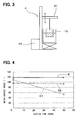
- water-shedding properties of the coating structures E, C1 and C2 are evaluated with a surface-free-energy measuring device (CA-VE type made by Kyowa Interface Science Co., Ltd) by measuring water contact angles in the conditions of ⁇ 0.7 mm of a syringe diameter, 3 to 4 ⁇ l of a measuring solution amount, ⁇ /2 method, and a parallel contact angle.
- CA-VE type made by Kyowa Interface Science Co., Ltd
- FIG. 4 is a graph showing relationships between the water contact angles of the coating structures E, C1 and C2 and heating times at 250 °C until 50 hours.
- the water contact angle (i.e., water-shedding property) of the coating structure C1 is substantially reduced by heating.
- the water-shedding property of the coating structure C2 is not reduced as such by heating.
- an initial water-shedding property of the coating structure C2 is lower than that of the coating structure C1.
- an initial water-shedding property of the coating structure E is higher than those of the coating structures C1 and C2, and the water-shedding property of the coating structure E is not reduced by heating.
- the coating structure E according to the second embodiment includes both the fluorine-based film 12 having the sufficient water-shedding property, and the NiP/PTFE composite film 11 having the sufficient thermal resistance and the water-shedding property. Therefore, the coating structure E has the sufficient water-shedding property which is not reduced by heating.
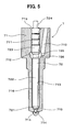
- a coating structure 1 similar to that of the first embodiment is used for a fuel injection nozzle 7.
- the fuel injection nozzle 7 can be used for a common-rail injection system of a diesel engine for injecting a high-pressure fuel into cylinders of the diesel engine.
- the injection nozzle 7 includes a nozzle body 71 and a needle 72.
- the injection nozzle 7 is set in a nozzle holder (not shown), and is attached to the diesel engine.
- the nozzle body 71 includes a guide hole 710 in which the needle 72 is inserted, a sliding hole part 711 adjacent to an opening end part 719 of the guide hole 710, a fuel storing part 712 provided in the guide hole 710, a fuel introducing passage 713 connected to the fuel storing part 712, a cone-shaped valve seat 715 located at a leading end part of the guide hole 710, and a plurality of injection holes 714 provided to penetrate through the valve seat 715.
- the guide hole 710 is provided in the nozzle body 71 to extend in an axial direction.
- the fuel storing part 712 is provided by expanding an inside diameter of the guide hole 710 for all circumstances, and has a circular space on an outer peripheral side of the needle 72 inserted in the guide hole 710.
- the fuel introducing passage 713 is provided in the nozzle body 71 for introducing the high-pressure fuel, which has been supplied to the nozzle holder, to the fuel storing part 712.
- the needle 72 includes a sliding part 723 inserted in the sliding hole part 711 so that the sliding part 723 is slidable, a cone-shaped valve part 721 for opening and closing the injection holes 714 by seating on and separating from the valve seat 715, a shaft part 722 for connecting the sliding part 723 and the valve part 721, and a journal part 724 on an axial end side of the sliding part 723.
- An outside diameter of the shaft part 722 is smaller than that of the sliding part 723.
- the shaft part 722 is inserted in the guide hole 710 for forming a fuel passage 716 with the guide hole 710.
- a pressure-receiving surface 725 and a small diameter part 726 are formed in a part of the shaft part 722 against the fuel storing part 712.
- the pressure-receiving surface 725 is formed to be taper-shaped in which a diameter becomes small from the side of the sliding part 723 to the small diameter part 726.
- a diameter of the small diameter part 726 is the smallest in the shaft part 722.
- the pressure-receiving surface 725 and the small diameter part 726 form the fuel storing part 712 with the nozzle body 71.
- the nozzle body 71 is operated as described bellow.
- the high-pressure fuel is pumped by a fuel pump (not shown) through the fuel introducing passage 713, and is stored in the fuel storing part 712.
- a fuel pressure of the fuel storing part 712 which is applied to the pressure-receiving surface 725 becomes higher than a pressure in a direction that the needle 72 closes a valve
- the needle 72 is lifted-up by a predetermined amount in the guide hole 710.
- the valve part 721 is separated from the valve seat 715, the fuel passage 716 and the injection holes 714 are connected, and the high-pressure fuel is injected from the plurality of injection holes 714 into the cylinders of the engine.
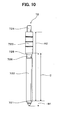
- the coating structure 1 according to the third embodiment of the invention is formed on a part of the needle 72.
- the coating structure 1 having the surface-smoothing layer 11 and the fluorine-based film 12 is formed on the needle 72 as the metal member 10.
- the coating structure 1 is formed on the area C of the needle 72, i.e., the valve part 721 and the shaft part 722.
- the DLC film 11 is used as the surface-smoothing layer 11.
- the DLC film 11 is formed on the area A1 of the needle 72, i.e., including the valve part 721, the shaft part 722, and the sliding part 723.
- the fluorine-based film 12 is formed on the area B1 of the needle 72, i.e., including the valve part 721 and the shaft part 722.
- the coating structure 1 is formed in an overlapped part in which the area A1 and the area B1 are overlapped.
- the DLC film 11 is formed, and on the area B1, the fluorine-based film 12 is formed.
- the sliding part 723 of the needle 72 only the DLC film 11 is formed. An abrasion resistance of the sliding part 723 is improved by a high-hardness and a high-solid lubrication property of the DLC film 11.
- a coating apparatus 5 for sputtering includes a sputter power source 51, a bias power source 56, an arc power source 57, a vacuum pump 52 for vacuating the coating apparatus 5, a first valve 53 for introducing argon gas 531 into the coating apparatus 5, a second valve 58 for introducing hydrocarbon gas into the coating apparatus 5, and a filament electron source 59.
- the sputter power source 51 is connected to a target electrode (-) 54.
- a target 55 which will be a filming material is set to the target electrode 54.
- the bias power source 56 is connected to the needle 72.
- argon gas 531 is introduced.
- the arc power source 57 supplies electricity to the filament electron source 59, so that the argon gas 531 becomes cations.
- the bias power source 56 supplies a negative potential to the needle 72
- the argon cations 531 hit against the needle 72, and a surface of the needle 72 is activated.
- the sputter power source 51 supplies a negative voltage to the target 55
- the argon cations 531 hit against the target 55 for taking out atoms 551.
- the atoms 551 pile-up on the needle 72 for forming the film. In this process, the needle 72 is located to be constantly rotated.
- the sputtering is performed on the predetermined area of the needle 72 with three different targets 55, i.e., Cr (chrome), W (tungsten), and C (carbon), in this order.
- the DLC film 11 including a Cr layer 111, a W/C layer 112, and a C layer 113 is formed as shown in FIG. 8.
- W and C are mixed, and a ratio of W in the W/C layer 112 is decreased as toward the C layer 113 in the thickness direction.
- the coating structure 1 is formed on a part of the needle 72 (in the third embodiment, the valve part 721 and the shaft part 722, for example), on which the foreign material such as a product generated from fuel may adhere.
- the coating structure 1 has the sufficient water-shedding property which is not reduced by heating. Therefore, the coating structure 1 can prevent the foreign material from adhering and piling-up on the surface of the needle 72. Thus, the coating structure 1 can keep a good sliding condition of the needle 72, and the fuel injection nozzle 7 can inject fuel for long time.
- the DLC film 11 is not formed on the journal part 724 of the needle 72.
- the journal part 724 is required to perform a gliding process for a dimensional coordination of the needle 72 after forming the DLC film 11.
- the gliding process becomes difficult. Therefore, the DLC film 11 is not formed on the journal part 724.
- the DLC film 11 may be formed on the journal part 724.
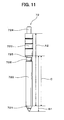
- the DLC film 11 may be formed on an area A1 of the needle 72, and the fluorine-based film 12 may be formed on an area B2 of the needle 72.
- the DLC film 11 may be formed on an area A2 of the needle 72, and the fluorine-based film 12 may be formed on an area B1 of the needle 72.
- the DLC film 11 may be formed on the area A2 of the needle 72, and the fluorine-based film 12 may be formed on the area B2 of the needle 72.
- the coating structure 1 is formed on the area C in which the area A1 or A2 and the area B1 or B2 overlap with each other.
- the DLC film 11 may be formed on the area A1 or A2 in the needle 72 based on the situation.
- the DLC film 11 may be formed on the area A1 of the needle 72 because the DLC film 11 can be formed easily.
- the DLC film 11 is preferred to be formed on the area A2 of the needle 72, which excludes the valve part 721.
- the valve part 721 may deteriorate with time because a friction is generated when the valve part 721 seats on and separates from the valve seat 715. Therefore, when the valve part 721 is checked, the valve part 721 may be optimized in accordance with a prediction of the deterioration.
- the DLC film 11 is formed on the valve part 721, a pattern of the deterioration may be changed.
- the valve part 721 is optimized similarly to the conventional case, a problem may be occurred. Therefore, in the conventional product, the DLC film 11 is formed on the area A2 in which the valve part 72 is excluded from the area A1.
- the surface-smoothing layer 11 may be formed on the shaft part 722 and a part of the sliding part 723.
- the surface-smoothing layer 11 may be formed on the valve part 721, the shaft part 722, and a part of the sliding part 723.
- the surface of the needle 72 can be smoothed. Therefore, the fluorine-based film 12 formed on the surface-smoothing layer 11 becomes uniform without a sink, and can provide the sufficient water-shedding property which is not reduced by heating.
- the fluorine-based film 12 may be formed on a part of the shaft part 722. Alternatively, the fluorine-based film 12 may be formed on the valve part 721 and a part of the shaft part 722. In each case, the fluorine-based film 12 can provide the sufficient water-shedding property on the predetermined portion of the needle 72.
- the fluorine-based film 12 may be formed on an area which is not less than 80% of the shaft part 722. In this case, the fluorine-based film 12 can sufficiently prevent the needle 72 from adhering and piling-up of the foreign material such as the product generated from fuel.
- a coating structure (1, E) for a metal member (10) includes a surface-smoothing layer (11, 13, 14) formed on the metal member (10) for smoothing a surface of the metal member (10), and a fluorine-based film (12) formed on the surface-smoothing layer (11, 13, 14).
- the fluorine-based film (12) can be formed by applying a fluorine-containing solution (120) on the surface-smoothing layer (11, 13, 14), and by drying the fluorine-containing solution (120).
- the coating structure (1, E) can be suitably used for a fuel injection nozzle (7).
Landscapes
- Chemical & Material Sciences (AREA)
- Engineering & Computer Science (AREA)
- Mechanical Engineering (AREA)
- Chemical Kinetics & Catalysis (AREA)
- Materials Engineering (AREA)
- Metallurgy (AREA)
- Organic Chemistry (AREA)
- Inorganic Chemistry (AREA)
- General Chemical & Material Sciences (AREA)
- Combustion & Propulsion (AREA)
- General Engineering & Computer Science (AREA)
- Dispersion Chemistry (AREA)
- Manufacturing & Machinery (AREA)
- Fuel-Injection Apparatus (AREA)
- Application Of Or Painting With Fluid Materials (AREA)
- Other Surface Treatments For Metallic Materials (AREA)
- Chemically Coating (AREA)
- Physical Vapour Deposition (AREA)
Applications Claiming Priority (2)
| Application Number | Priority Date | Filing Date | Title |
|---|---|---|---|
| JP2006133845 | 2006-05-12 | ||
| JP2007050745A JP5176337B2 (ja) | 2006-05-12 | 2007-02-28 | 皮膜構造及びその形成方法 |
Publications (3)
| Publication Number | Publication Date |
|---|---|
| EP1854909A2 true EP1854909A2 (fr) | 2007-11-14 |
| EP1854909A3 EP1854909A3 (fr) | 2007-12-26 |
| EP1854909B1 EP1854909B1 (fr) | 2015-02-25 |
Family
ID=38255066
Family Applications (1)
| Application Number | Title | Priority Date | Filing Date |
|---|---|---|---|
| EP20070107945 Not-in-force EP1854909B1 (fr) | 2006-05-12 | 2007-05-10 | Structure de revêtement et son procédé de réalisation |
Country Status (4)
| Country | Link |
|---|---|
| US (2) | US20070264491A1 (fr) |
| EP (1) | EP1854909B1 (fr) |
| JP (1) | JP5176337B2 (fr) |
| CN (1) | CN101070002B (fr) |
Cited By (4)
| Publication number | Priority date | Publication date | Assignee | Title |
|---|---|---|---|---|
| EP2644879A1 (fr) * | 2012-03-26 | 2013-10-02 | Robert Bosch Gmbh | Procédé de fabrication d'une électrovanne |
| FR3011308A1 (fr) * | 2013-10-02 | 2015-04-03 | Vallourec Oil & Gas France | Element de connexion d'un composant tubulaire recouvert d'un depot metallique composite |
| CN107475667A (zh) * | 2017-08-16 | 2017-12-15 | 信利光电股份有限公司 | 一种高疏水类金刚石薄膜及其制备方法 |
| US20220351749A1 (en) * | 2021-04-28 | 2022-11-03 | Seagate Technology Llc | Coated disk separator plate, electronic devices that include one or more coated disk separator plates, and related methods of making and using |
Families Citing this family (21)
| Publication number | Priority date | Publication date | Assignee | Title |
|---|---|---|---|---|
| JP5176337B2 (ja) * | 2006-05-12 | 2013-04-03 | 株式会社デンソー | 皮膜構造及びその形成方法 |
| DE112009001611T5 (de) * | 2008-06-30 | 2011-05-12 | Caterpillar Inc., Peoria | Beschichtung für eine Hochdruckkomponente |
| DE102009003192A1 (de) * | 2009-05-18 | 2010-11-25 | Robert Bosch Gmbh | Verschleißschutzschichtanordnung sowie Bauelement mit Verschleißschutzschichtanordnung |
| JP5465168B2 (ja) * | 2010-12-27 | 2014-04-09 | 日本発條株式会社 | 粘性液体供給ノズルへの潤滑性メッキ層の形成方法及び粘性液体供給ノズル |
| US20140097275A1 (en) * | 2012-10-10 | 2014-04-10 | Caterpillar Inc. | Fuel injector with nozzle passages having electroless nickel coating |
| US9051910B2 (en) * | 2013-01-31 | 2015-06-09 | Caterpillar Inc. | Valve assembly for fuel system and method |
| FR3011309B1 (fr) * | 2013-10-02 | 2015-10-30 | Vallourec Oil & Gas France | Butee pour un composant tubulaire recouverte d'un depot metallique composite |
| KR20150039548A (ko) * | 2013-10-02 | 2015-04-10 | 가부시키가이샤 시마노 | 접동 부재, 접동 부재를 이용한 자전거용 부품, 접동 부재를 이용한 낚시구용 부품, 및 접동 부재의 제조 방법 |
| EP3162916A4 (fr) * | 2014-06-25 | 2018-01-24 | IHI Corporation | Film de revêtement pour la suppression de l'adhérence de dépôts et élément de circuit d'écoulement pourvu dudit film de revêtement |
| CN104480423B (zh) * | 2014-11-20 | 2016-11-30 | 中国科学院宁波材料技术与工程研究所 | 一种利用超音速电弧喷涂制备超疏水涂层的方法 |
| DE102015225733A1 (de) * | 2015-12-17 | 2017-06-22 | Robert Bosch Gmbh | Kraftstoffeinspritzdüse |
| US10626834B2 (en) | 2016-05-03 | 2020-04-21 | GM Global Technology Operations LLC | Fuel injector for an internal combustion engine |
| JP2019100208A (ja) * | 2017-11-29 | 2019-06-24 | 株式会社デンソー | 燃料噴射弁 |
| WO2019108495A1 (fr) * | 2017-11-30 | 2019-06-06 | Cummins Inc. | Revêtement autocatalytique de nickel sur aiguille d'injecteur de carburant |
| DE112018007648T5 (de) * | 2018-05-22 | 2021-03-18 | Cummins Inc. | Plasma-elektrolytisch polierte dieselmotorkomponenten |
| CN115697676B (zh) * | 2020-06-18 | 2025-10-17 | 帝斯克玛股份有限公司 | 具有疏水特性的容器成型和填充系统 |
| CN111593334B (zh) * | 2020-07-10 | 2021-10-29 | 瑞声新能源发展(常州)有限公司科教城分公司 | 模具表面处理方法及其镀膜结构 |
| USD1034698S1 (en) * | 2020-12-15 | 2024-07-09 | Transportation Ip Holdings, Llc | Fuel injector and electrical box of the fuel injector |
| CN116816504A (zh) | 2022-03-22 | 2023-09-29 | 通用电气公司 | 调节表面的ζ电位以减少燃料和油系统中的焦炭 |
| CN116814311B (zh) | 2022-03-22 | 2025-09-09 | 通用电气公司 | 用于燃料和油系统中焦炭抑制的化学物质、应用和输送方法 |
| JP7674567B1 (ja) | 2024-06-26 | 2025-05-09 | 日鉄鋼板株式会社 | 植物栽培容器 |
Citations (9)
| Publication number | Priority date | Publication date | Assignee | Title |
|---|---|---|---|---|
| JPS5647926B2 (fr) | 1978-04-03 | 1981-11-12 | ||
| EP0453633A1 (fr) | 1990-04-26 | 1991-10-30 | Nkk Corporation | Tôle métallique plaquée avec une pluralité de couches de plaquage, une dénudabilité excellente et ayant une dureté élevée |
| JPH08144893A (ja) | 1994-11-21 | 1996-06-04 | Nippondenso Co Ltd | 燃料噴射ノズル |
| US5725907A (en) | 1994-10-28 | 1998-03-10 | Hashimoto Chemical Co., Ltd. | Metal material formed with fluorocarbon film, process for preparing the material and apparatus made with use of the material |
| EP1287953A1 (fr) | 2000-06-05 | 2003-03-05 | KAI R&D CENTER CO., LTD. | Lame de coupe et procede de fabrication de cette lame |
| US20030121158A1 (en) | 2000-02-29 | 2003-07-03 | The Gillette Company, A Delaware Corporation | Razor blade technology |
| US20040000601A1 (en) | 2002-06-28 | 2004-01-01 | Yutaka Niwa | Fuel injection nozzle having coating layer and manufacturing method thereof |
| US20050069237A1 (en) | 2003-09-25 | 2005-03-31 | Mickelson James E. | Corrosion-resistant and stain-resistant component and method for manufacturing same |
| WO2006030999A1 (fr) | 2004-09-16 | 2006-03-23 | Bukwang Technology Co., Ltd. | Procede de depot autocatalytique et couche de depot ainsi obtenue |
Family Cites Families (48)
| Publication number | Priority date | Publication date | Assignee | Title |
|---|---|---|---|---|
| US3645861A (en) * | 1970-09-08 | 1972-02-29 | Kewanee Oil Co | Method of plating on stainless steel |
| JPS5647926A (en) * | 1979-09-21 | 1981-04-30 | Hitachi Ltd | Magnetic recording medium |
| JPS5745036A (en) * | 1980-09-02 | 1982-03-13 | Mitsui Toatsu Chem Inc | Blow forming method |
| JPS6033913B2 (ja) * | 1982-09-24 | 1985-08-06 | 日本バルカ−工業株式会社 | フツ素樹脂コ−テイング方法 |
| DE3545826A1 (de) * | 1984-12-24 | 1986-06-26 | Kabushiki Kaisha Riken, Tokio/Tokyo | Kolbenring |
| US4833041A (en) * | 1986-12-08 | 1989-05-23 | Mccomas C Edward | Corrosion/wear-resistant metal alloy coating compositions |
| US4908280A (en) * | 1989-07-10 | 1990-03-13 | Toyo Kohan Co., Ltd. | Scratch and corrosion resistant, formable nickel plated steel sheet, and manufacturing method |
| US5086615A (en) * | 1990-02-15 | 1992-02-11 | A. B. Carter, Inc. | Coated spinning rings and travelers |
| JPH049498A (ja) * | 1990-04-26 | 1992-01-14 | Nkk Corp | 優れた剥離性および高い硬度を有するニツケル‐燐合金めつき金属板およびその製造方法 |
| JP3045612B2 (ja) * | 1992-06-22 | 2000-05-29 | 東洋鋼鈑株式会社 | 高耐食性ニッケルめっき鋼帯およびその製造法 |
| JPH06122962A (ja) * | 1992-10-09 | 1994-05-06 | Shincron:Kk | 物体の表面処理方法 |
| US5470661A (en) * | 1993-01-07 | 1995-11-28 | International Business Machines Corporation | Diamond-like carbon films from a hydrocarbon helium plasma |
| JPH06300129A (ja) * | 1993-04-08 | 1994-10-28 | Teikoku Piston Ring Co Ltd | ピストンリング |
| US5491864A (en) * | 1994-03-31 | 1996-02-20 | The Procter & Gamble Company | Implement for personal cleansing and method of construction |
| US5630275A (en) * | 1994-08-23 | 1997-05-20 | Warner-Lambert Company | Multi-blade razor head with improved performance |
| BR9509053A (pt) * | 1994-09-30 | 1997-09-30 | Henkel Corp | Processo para prover um substrato metálico com um revestimento protetor contendo um agente aglutinante orgánico |
| US5721055A (en) * | 1995-01-03 | 1998-02-24 | Surface Technology, Inc. | Lubricated textile spinning machinery parts |
| US6468642B1 (en) * | 1995-10-03 | 2002-10-22 | N.V. Bekaert S.A. | Fluorine-doped diamond-like coatings |
| JPH09112392A (ja) * | 1995-10-13 | 1997-04-28 | Denso Corp | 内燃機関用燃料噴射ノズル及びその製造方法 |
| US5783261A (en) * | 1996-07-11 | 1998-07-21 | Ford Global Technologies, Inc. | Using a coated fuel injector and method of making |
| US5985459A (en) * | 1996-10-31 | 1999-11-16 | The Gillette Company | Method of treating razor blade cutting edges |
| US6511156B1 (en) * | 1997-09-22 | 2003-01-28 | Citizen Watch Co., Ltd. | Ink-jet head nozzle plate, its manufacturing method and ink-jet head |
| US6156439A (en) * | 1997-10-21 | 2000-12-05 | General Electric Company | Coating for preventing formation of deposits on surfaces contacting hydrocarbon fluids and method therefor |
| US6062498A (en) * | 1998-04-27 | 2000-05-16 | Stanadyne Automotive Corp. | Fuel injector with at least one movable needle-guide |
| JP3567732B2 (ja) * | 1998-04-28 | 2004-09-22 | 株式会社日立製作所 | 燃料噴射弁 |
| US6105261A (en) * | 1998-05-26 | 2000-08-22 | Globix Technologies, Inc. | Self sharpening blades and method for making same |
| US6523803B1 (en) * | 1998-09-03 | 2003-02-25 | Micron Technology, Inc. | Mold apparatus used during semiconductor device fabrication |
| US6802457B1 (en) * | 1998-09-21 | 2004-10-12 | Caterpillar Inc | Coatings for use in fuel system components |
| DE19860526A1 (de) * | 1998-12-30 | 2000-07-06 | Basf Ag | Wärmeüberträger mit verringerter Neigung, Ablagerungen zu bilden und Verfahren zu deren Herstellung |
| US6145763A (en) * | 1998-12-30 | 2000-11-14 | Ford Global Technologies, Inc. | Carbonaceous deposit-resistant coating for fuel injectors |
| US6280834B1 (en) * | 1999-05-03 | 2001-08-28 | Guardian Industries Corporation | Hydrophobic coating including DLC and/or FAS on substrate |
| JP2001062720A (ja) * | 1999-08-30 | 2001-03-13 | Inst Of Physical & Chemical Res | 内面研削方法及び装置及び燃料噴射ノズル |
| US6318898B1 (en) * | 1999-10-15 | 2001-11-20 | Reliance Electric Technologies, Llc | Corrosion-resistant bearing and method for making same |
| WO2001061182A1 (fr) * | 2000-02-15 | 2001-08-23 | Caterpillar Inc. | Revetements de films fin pour composants d'injecteur |
| US6715693B1 (en) * | 2000-02-15 | 2004-04-06 | Caterpillar Inc | Thin film coating for fuel injector components |
| DE10016215A1 (de) * | 2000-03-31 | 2001-10-04 | Basf Ag | Verfahren zur Beschichtung von Apparaten und Apparateteilen für den chemischen Anlagenbau |
| US6508416B1 (en) * | 2000-04-28 | 2003-01-21 | Delphi Technologies, Inc. | Coated fuel injector valve |
| DE60116407T2 (de) * | 2000-05-09 | 2006-07-06 | Kabushiki Kaisha Riken | Amorphe oxidhaltige Kohlenstoffschicht |
| JP4681161B2 (ja) * | 2000-07-14 | 2011-05-11 | 大阪瓦斯株式会社 | メッキ皮膜及びそれを用いたメッキ被覆物 |
| JP4578716B2 (ja) * | 2001-05-08 | 2010-11-10 | 株式会社デンソー | ガソリン潤滑摺動部材 |
| EP2339050A1 (fr) * | 2001-10-24 | 2011-06-29 | Rohm and Haas Electronic Materials LLC | Stabilisants pour des solutions de placage sans courant et méthodes d'utilisation |
| JP2003206820A (ja) * | 2002-01-17 | 2003-07-25 | Keihin Corp | 電磁式燃料噴射弁 |
| US7152526B2 (en) * | 2002-01-29 | 2006-12-26 | Nihon New Chrome Co., Ltd. | Surface treated doctor blade |
| US7247249B2 (en) * | 2004-01-15 | 2007-07-24 | The Gillette Company | Method of treating razor blade cutting edges |
| JP2005256170A (ja) * | 2004-02-12 | 2005-09-22 | National Institute Of Advanced Industrial & Technology | 無電解ニッケルめっき方法及びそのめっき製品 |
| JP2005337374A (ja) * | 2004-05-27 | 2005-12-08 | Nissan Motor Co Ltd | 転動部材及びその製造方法 |
| US7244493B2 (en) * | 2004-11-12 | 2007-07-17 | Delphi Technologies, Inc. | Coated article |
| JP5176337B2 (ja) * | 2006-05-12 | 2013-04-03 | 株式会社デンソー | 皮膜構造及びその形成方法 |
-
2007
- 2007-02-28 JP JP2007050745A patent/JP5176337B2/ja not_active Expired - Fee Related
- 2007-05-10 EP EP20070107945 patent/EP1854909B1/fr not_active Not-in-force
- 2007-05-10 CN CN200710103218XA patent/CN101070002B/zh not_active Expired - Fee Related
- 2007-05-11 US US11/798,240 patent/US20070264491A1/en not_active Abandoned
-
2010
- 2010-06-18 US US12/801,647 patent/US20100279145A1/en not_active Abandoned
Patent Citations (9)
| Publication number | Priority date | Publication date | Assignee | Title |
|---|---|---|---|---|
| JPS5647926B2 (fr) | 1978-04-03 | 1981-11-12 | ||
| EP0453633A1 (fr) | 1990-04-26 | 1991-10-30 | Nkk Corporation | Tôle métallique plaquée avec une pluralité de couches de plaquage, une dénudabilité excellente et ayant une dureté élevée |
| US5725907A (en) | 1994-10-28 | 1998-03-10 | Hashimoto Chemical Co., Ltd. | Metal material formed with fluorocarbon film, process for preparing the material and apparatus made with use of the material |
| JPH08144893A (ja) | 1994-11-21 | 1996-06-04 | Nippondenso Co Ltd | 燃料噴射ノズル |
| US20030121158A1 (en) | 2000-02-29 | 2003-07-03 | The Gillette Company, A Delaware Corporation | Razor blade technology |
| EP1287953A1 (fr) | 2000-06-05 | 2003-03-05 | KAI R&D CENTER CO., LTD. | Lame de coupe et procede de fabrication de cette lame |
| US20040000601A1 (en) | 2002-06-28 | 2004-01-01 | Yutaka Niwa | Fuel injection nozzle having coating layer and manufacturing method thereof |
| US20050069237A1 (en) | 2003-09-25 | 2005-03-31 | Mickelson James E. | Corrosion-resistant and stain-resistant component and method for manufacturing same |
| WO2006030999A1 (fr) | 2004-09-16 | 2006-03-23 | Bukwang Technology Co., Ltd. | Procede de depot autocatalytique et couche de depot ainsi obtenue |
Cited By (10)
| Publication number | Priority date | Publication date | Assignee | Title |
|---|---|---|---|---|
| EP2644879A1 (fr) * | 2012-03-26 | 2013-10-02 | Robert Bosch Gmbh | Procédé de fabrication d'une électrovanne |
| US9429245B2 (en) | 2012-03-26 | 2016-08-30 | Robert Bosch Gmbh | Method for manufacturing a solenoid valve |
| US9885101B2 (en) | 2012-03-26 | 2018-02-06 | Robert Bosch Gmbh | Method for manufacturing a solenoid valve |
| FR3011308A1 (fr) * | 2013-10-02 | 2015-04-03 | Vallourec Oil & Gas France | Element de connexion d'un composant tubulaire recouvert d'un depot metallique composite |
| WO2015049097A1 (fr) * | 2013-10-02 | 2015-04-09 | Vallourec Oil And Gas France | Raccord pour un composant tubulaire recouvert d'un revêtement composite métallique et procédé de formation de cet élément |
| US10526851B2 (en) | 2013-10-02 | 2020-01-07 | Vallourec Oil And Gas France | Connecting element for a tubular component overlaid with a metallic composite deposit and method of obtaining such element |
| EA035716B1 (ru) * | 2013-10-02 | 2020-07-29 | Валлурек Ойл Энд Гес Франс | Соединительный элемент для трубчатого компонента, покрытый осажденным слоем композиционного материала на основе металла, и способ получения такого элемента |
| CN107475667A (zh) * | 2017-08-16 | 2017-12-15 | 信利光电股份有限公司 | 一种高疏水类金刚石薄膜及其制备方法 |
| US20220351749A1 (en) * | 2021-04-28 | 2022-11-03 | Seagate Technology Llc | Coated disk separator plate, electronic devices that include one or more coated disk separator plates, and related methods of making and using |
| US11676633B2 (en) * | 2021-04-28 | 2023-06-13 | Seagate Technology Llc | Coated disk separator plate, electronic devices that include one or more coated disk separator plates, and related methods of making and using |
Also Published As
| Publication number | Publication date |
|---|---|
| CN101070002B (zh) | 2012-04-18 |
| JP2007327135A (ja) | 2007-12-20 |
| US20070264491A1 (en) | 2007-11-15 |
| EP1854909B1 (fr) | 2015-02-25 |
| EP1854909A3 (fr) | 2007-12-26 |
| CN101070002A (zh) | 2007-11-14 |
| US20100279145A1 (en) | 2010-11-04 |
| JP5176337B2 (ja) | 2013-04-03 |
Similar Documents
| Publication | Publication Date | Title |
|---|---|---|
| EP1854909B1 (fr) | Structure de revêtement et son procédé de réalisation | |
| US8006715B2 (en) | Valve with thin-film coating | |
| CN103334106B (zh) | 一种钛及钛合金球阀密封副和摩擦副的表面硬化处理方法 | |
| CN111183269B (zh) | 具有耐蚀滑动面的涂覆阀门部件 | |
| CN101709470A (zh) | 一种含有原位生成扩散障的复合涂层制备方法 | |
| JP2013091811A (ja) | アルミニウム又はアルミニウム合金を基板とする多層膜積層体及びその積層方法 | |
| US20080152491A1 (en) | Coatings for use in fuel system components | |
| JP6890703B2 (ja) | 内燃機関用のライナー | |
| JP2018076873A5 (ja) | 内燃機関用のライナー | |
| US7434793B2 (en) | Coating for a throttle body | |
| KR20260012187A (ko) | 표면 코팅을 포함한 밸브 | |
| CN101550539B (zh) | 一种在陶瓷阀芯表面沉积防护薄膜的方法 | |
| CN118202092A (zh) | 在外表面、内表面或两者上包含表面涂层的制品 | |
| CN216550673U (zh) | 一种液压元件用多层结构防护涂层 | |
| JPH07216548A (ja) | 燃料噴射ノズル装置の耐摩耗性摺動部材 | |
| JP2009052521A (ja) | 燃料噴射ノズルとその製造方法 | |
| JP2008231961A (ja) | 燃料噴射弁 | |
| CN105734489A (zh) | 一种复合涂层氮气弹簧及其制备方法 | |
| Singh et al. | Magnetron sputtered TiN coatings modified by chromium, nickel and electroless nickel (EN) interlayers on mild steel | |
| US20210269935A1 (en) | Plasma electrolytic polished diesel engine components | |
| Budinski et al. | Tribological Properties of Crystalline Hardcoat on Aluminum | |
| JPH0731854U (ja) | カーボン硬質被膜を有する基材 | |
| JP2013108359A (ja) | 気化器 |
Legal Events
| Date | Code | Title | Description |
|---|---|---|---|
| PUAI | Public reference made under article 153(3) epc to a published international application that has entered the european phase |
Free format text: ORIGINAL CODE: 0009012 |
|
| AK | Designated contracting states |
Kind code of ref document: A2 Designated state(s): AT BE BG CH CY CZ DE DK EE ES FI FR GB GR HU IE IS IT LI LT LU LV MC MT NL PL PT RO SE SI SK TR |
|
| AX | Request for extension of the european patent |
Extension state: AL BA HR MK YU |
|
| PUAL | Search report despatched |
Free format text: ORIGINAL CODE: 0009013 |
|
| AK | Designated contracting states |
Kind code of ref document: A3 Designated state(s): AT BE BG CH CY CZ DE DK EE ES FI FR GB GR HU IE IS IT LI LT LU LV MC MT NL PL PT RO SE SI SK TR |
|
| AX | Request for extension of the european patent |
Extension state: AL BA HR MK YU |
|
| 17P | Request for examination filed |
Effective date: 20080626 |
|
| AKX | Designation fees paid |
Designated state(s): DE FR GB |
|
| 17Q | First examination report despatched |
Effective date: 20081218 |
|
| GRAP | Despatch of communication of intention to grant a patent |
Free format text: ORIGINAL CODE: EPIDOSNIGR1 |
|
| INTG | Intention to grant announced |
Effective date: 20141016 |
|
| GRAS | Grant fee paid |
Free format text: ORIGINAL CODE: EPIDOSNIGR3 |
|
| GRAA | (expected) grant |
Free format text: ORIGINAL CODE: 0009210 |
|
| AK | Designated contracting states |
Kind code of ref document: B1 Designated state(s): DE FR GB |
|
| REG | Reference to a national code |
Ref country code: GB Ref legal event code: FG4D |
|
| REG | Reference to a national code |
Ref country code: DE Ref legal event code: R096 Ref document number: 602007040319 Country of ref document: DE Effective date: 20150409 |
|
| REG | Reference to a national code |
Ref country code: FR Ref legal event code: PLFP Year of fee payment: 9 |
|
| REG | Reference to a national code |
Ref country code: DE Ref legal event code: R084 Ref document number: 602007040319 Country of ref document: DE |
|
| PGFP | Annual fee paid to national office [announced via postgrant information from national office to epo] |
Ref country code: DE Payment date: 20150521 Year of fee payment: 9 Ref country code: GB Payment date: 20150521 Year of fee payment: 9 |
|
| REG | Reference to a national code |
Ref country code: GB Ref legal event code: 746 Effective date: 20150803 |
|
| PGFP | Annual fee paid to national office [announced via postgrant information from national office to epo] |
Ref country code: FR Payment date: 20150521 Year of fee payment: 9 |
|
| REG | Reference to a national code |
Ref country code: DE Ref legal event code: R097 Ref document number: 602007040319 Country of ref document: DE |
|
| PLBE | No opposition filed within time limit |
Free format text: ORIGINAL CODE: 0009261 |
|
| STAA | Information on the status of an ep patent application or granted ep patent |
Free format text: STATUS: NO OPPOSITION FILED WITHIN TIME LIMIT |
|
| 26N | No opposition filed |
Effective date: 20151126 |
|
| REG | Reference to a national code |
Ref country code: DE Ref legal event code: R119 Ref document number: 602007040319 Country of ref document: DE |
|
| GBPC | Gb: european patent ceased through non-payment of renewal fee |
Effective date: 20160510 |
|
| REG | Reference to a national code |
Ref country code: FR Ref legal event code: ST Effective date: 20170131 |
|
| PG25 | Lapsed in a contracting state [announced via postgrant information from national office to epo] |
Ref country code: FR Free format text: LAPSE BECAUSE OF NON-PAYMENT OF DUE FEES Effective date: 20160531 Ref country code: DE Free format text: LAPSE BECAUSE OF NON-PAYMENT OF DUE FEES Effective date: 20161201 |
|
| PG25 | Lapsed in a contracting state [announced via postgrant information from national office to epo] |
Ref country code: GB Free format text: LAPSE BECAUSE OF NON-PAYMENT OF DUE FEES Effective date: 20160510 |