EP1854932A2 - Dispositif de mise à niveau - Google Patents
Dispositif de mise à niveau Download PDFInfo
- Publication number
- EP1854932A2 EP1854932A2 EP07009295A EP07009295A EP1854932A2 EP 1854932 A2 EP1854932 A2 EP 1854932A2 EP 07009295 A EP07009295 A EP 07009295A EP 07009295 A EP07009295 A EP 07009295A EP 1854932 A2 EP1854932 A2 EP 1854932A2
- Authority
- EP
- European Patent Office
- Prior art keywords
- leveling
- rail
- shaped
- carriage
- legs
- Prior art date
- Legal status (The legal status is an assumption and is not a legal conclusion. Google has not performed a legal analysis and makes no representation as to the accuracy of the status listed.)
- Withdrawn
Links
Images


Classifications
-
- E—FIXED CONSTRUCTIONS
- E04—BUILDING
- E04B—GENERAL BUILDING CONSTRUCTIONS; WALLS, e.g. PARTITIONS; ROOFS; FLOORS; CEILINGS; INSULATION OR OTHER PROTECTION OF BUILDINGS
- E04B2/00—Walls, e.g. partitions, for buildings; Wall construction with regard to insulation; Connections specially adapted to walls
- E04B2/74—Removable non-load-bearing partitions; Partitions with a free upper edge
- E04B2/82—Removable non-load-bearing partitions; Partitions with a free upper edge characterised by the manner in which edges are connected to the building; Means therefor; Special details of easily-removable partitions as far as related to the connection with other parts of the building
- E04B2/825—Removable non-load-bearing partitions; Partitions with a free upper edge characterised by the manner in which edges are connected to the building; Means therefor; Special details of easily-removable partitions as far as related to the connection with other parts of the building the connection between the floor and the ceiling being achieved without any restraining forces acting in the plane of the partition
-
- E—FIXED CONSTRUCTIONS
- E04—BUILDING
- E04B—GENERAL BUILDING CONSTRUCTIONS; WALLS, e.g. PARTITIONS; ROOFS; FLOORS; CEILINGS; INSULATION OR OTHER PROTECTION OF BUILDINGS
- E04B2/00—Walls, e.g. partitions, for buildings; Wall construction with regard to insulation; Connections specially adapted to walls
- E04B2/74—Removable non-load-bearing partitions; Partitions with a free upper edge
- E04B2/7407—Removable non-load-bearing partitions; Partitions with a free upper edge assembled using frames with infill panels or coverings only; made-up of panels and a support structure incorporating posts
- E04B2/7448—Removable non-load-bearing partitions; Partitions with a free upper edge assembled using frames with infill panels or coverings only; made-up of panels and a support structure incorporating posts with separate framed panels without intermediary posts, extending from floor to ceiling
-
- E—FIXED CONSTRUCTIONS
- E06—DOORS, WINDOWS, SHUTTERS, OR ROLLER BLINDS IN GENERAL; LADDERS
- E06B—FIXED OR MOVABLE CLOSURES FOR OPENINGS IN BUILDINGS, VEHICLES, FENCES OR LIKE ENCLOSURES IN GENERAL, e.g. DOORS, WINDOWS, BLINDS, GATES
- E06B3/00—Window sashes, door leaves, or like elements for closing wall or like openings; Layout of fixed or moving closures, e.g. windows in wall or like openings; Features of rigidly-mounted outer frames relating to the mounting of wing frames
- E06B3/02—Wings made completely of glass
-
- E—FIXED CONSTRUCTIONS
- E06—DOORS, WINDOWS, SHUTTERS, OR ROLLER BLINDS IN GENERAL; LADDERS
- E06B—FIXED OR MOVABLE CLOSURES FOR OPENINGS IN BUILDINGS, VEHICLES, FENCES OR LIKE ENCLOSURES IN GENERAL, e.g. DOORS, WINDOWS, BLINDS, GATES
- E06B3/00—Window sashes, door leaves, or like elements for closing wall or like openings; Layout of fixed or moving closures, e.g. windows in wall or like openings; Features of rigidly-mounted outer frames relating to the mounting of wing frames
- E06B3/32—Arrangements of wings characterised by the manner of movement; Arrangements of movable wings in openings; Features of wings or frames relating solely to the manner of movement of the wing
- E06B3/34—Arrangements of wings characterised by the manner of movement; Arrangements of movable wings in openings; Features of wings or frames relating solely to the manner of movement of the wing with only one kind of movement
- E06B3/42—Sliding wings; Details of frames with respect to guiding
- E06B3/46—Horizontally-sliding wings
- E06B3/4609—Horizontally-sliding wings for windows
Definitions
- the invention relates to a device for leveling a partition, with a bottom construction and a ceiling construction, to which a wall element of the partition wall is attached.
- a generic, non-load-bearing partition is from the WO 2004/038151 A known.
- This is made of glass and comprises at least two frameless side parts, which are held on the floor and a ceiling construction and at least one frameless glass element, which is held on the two side parts and on the ceiling construction.
- For attachment is proposed in this WO-A that these glass elements are fixed with a permanently elastic mass in U-shaped profiles of the ceiling construction or floor construction.
- permanently elastic mass acrylic or silicone materials are proposed. A leveling is thus very difficult.
- Object of the present invention is to simplify the height leveling or height compensation of a partition assembly related.
- the bottom construction of the device comprises at least one leveling element, which consists of a first and a second leveling slide arranged thereon, both having at least one inclined plane, the inclined planes facing each other and at least approximately parallel to each other, and on the first leveling carriage a spindle element is arranged which is operatively connected to the second leveling carriage and / or in that the ceiling construction comprises a first and a second leveling rail, the first leveling rail on an inner surface and the second leveling rail on an outer surface respectively comprise a latching device, which are in operative connection with each other.
- the latching devices of the first and the second leveling rail can each be formed by a toothing - viewed in cross-section - the surface of the leveling rail in this area, whereby the Aufschieb sadness and Verrasthus the two locking devices is simplified with each other, especially if in the assembled state, an oblique edge of Teeth points in the direction of the bottom construction, since thus the sliding over this oblique flank is facilitated by the locking device of the second leveling rail.
- the first leveling rail can be formed by an at least approximately U-shaped profile - viewed in cross-section - with a base and two legs connected thereto, whereby this first leveling rail can overlap the second leveling rail at least in the region of the latching device and thus a better grip is possible ,
- the U-shaped profile of the first leveling rail on both leg inner sides has the latching device, whereby a uniform or at least approximately uniform distribution of the forces occurring on both legs is achieved.
- the U-shaped profile in the region of the base on the leg outer sides each have a lateral angle element, which is the same direction as the legs of the U-shaped profile, so that at these angle elements, the concern and / or fastening of the wall element is simplified to the second leveling rail.
- the legs of the U-shaped profile of the second leveling rail can be formed elastically deformable in their relative position to each other, for example, can be bent against each other, whereby the introducibility of the locking device of the second leveling rail is facilitated in the locking device of the first leveling rail.
- a spreading element can be arranged which presses the two legs of this profile of the second leveling rail against the legs of the profile of the first leveling rail, whereby the Ausringtonplant& and thus the bracket is improved at a certain height.
- the expansion element may have on an outer side web-shaped extensions which are guided in groove-shaped recesses on an inner side of the legs of the U-shaped profile of the second leveling rail, whereby on the one hand the precise introduction of the spreader is made possible and on the other hand, the spreader is held securely in position.
- the web-shaped extensions over their length profile conically widening and / or the groove-shaped recesses may be formed conically tapering over its length.
- the second leveling rail may be shorter than the first leveling rail so that the second leveling rail may be located anywhere within the first leveling rail.
- the spindle element of the bottom construction can be formed by a threaded screw, which engages in an internal thread on the second leveling carriage, so that due to the fine coordinated pitch of the thread a very accurate leveling of the height is made possible and thus can be used on commercial products. It is thus also a stepless leveling possible.
- a first cylindrical holding element can be arranged with a continuous bore, wherein that internal thread is formed on the inner surface of the bore, so that a uniform possible force introduction is made possible in the leveling slide.
- first cylindrical support member is rotatably supported on the second leveling slide, so that canting in the internal thread by changing the inclination angle of the spindle member can be better prevented.
- the threaded screw may also be guided on the first leveling slide by a cylindrical second holding element, in which case again a better introduction of force into the leveling slide is achieved.
- This second holding element can also have a continuous bore for guiding the threaded screw in order to improve the guidance of the threaded screw in this holding element.
- this second holding element can be arranged rotatably on the first leveling carriage for reasons already mentioned above.
- the first leveling carriage may have an at least approximately U-shaped cross section with a base and two legs connected thereto, wherein at least one of the legs, preferably both, is formed on an inner surface at least partially a web extending at least approximately parallel to the inclined plane is arranged and wherein at least partially a groove-shaped recess is disposed in a lower region of the second leveling slide, preferably two opposing, which also at least approximately parallel to the inclined plane, wherein the web engages in the groove in order to better guide the second leveling slide to reach on the first leveling slide.
- the web and a side wall of the groove-shaped recess of the second leveling slide may be hook-shaped, whereby the support of the two elements is improved together.
- the groove-shaped recess may be formed in the lower portion of the second leveling carriage in a sidewall extension, so that the overlapping area between the two leveling carriages is increased.
- This sidewall extension may have a lateral offset to the inside, with respect to the side wall of the leveling slide.
- the sidewall extension can be designed to extend safely over only a portion of the length of the inclined plane of the second leveling carriage in order to reduce any forces that may occur due to friction of the two leveling carriages against each other.
- the first leveling carriage may have one or two recesses in its base, and the side wall extension (s) may be engageably formed in this recess (s), thereby enabling an end stop of the second upper leveling carriage in the region of its end position and thus a crossing of this point can be prevented.
- the length of the spindle element can be dimensioned relatively accurately to the adjustment, since due to the stop of the second leveling slide at the lowest point of its adjustment, the unscrewing of the spindle member from the internal thread can not be done.
- Mating surfaces of the inclined plane of the first and second leveling carriages may be provided with a friction reducing coating, for example a lubricating varnish, to reduce the force required for leveling, ie, the change in the relative position of the two leveling carriages to each other can be more easily performed.
- a friction reducing coating for example a lubricating varnish
- at least those areas are formed around the inclined plane of the first and the second leveling slide of a lubricious material, for example of polytetrafluoroethylene.
- Fig. 1 shows a partition 1.
- This consists of wall parts 2, in turn, a Gas element 3, a bottom structure 4 and a ceiling structure 5 for holding the glass element 3 have.
- the partition 1 is designed to be room-high, so that this partition 1 can be used to divide a larger room into individual rooms or for the separation of areas as a room divider, etc.
- the glass elements 3 may be formed by a safety glass known from the prior art and this glass may also have a coloring. It consists, for example, of 10 mm, 12 mm or 16 mm thick glass panes and these glass elements 3 are made of toughened safety glass or laminated safety glass, optionally with improved acoustics.
- a door element 6 can also be arranged between two wall parts 2.
- This door element 6 can also be designed in glass construction or are also so-called Vollbauten possible, as they are known from the prior art, for example, solid wood doors or doors with veneer or melamine plate coating.
- the glass thickness itself can also be selected in other dimensions than those mentioned.
- the partition wall 1 may be formed in a double-shell design, wherein successively two glass elements 3 are arranged which are fixed to respective opposite surfaces of the floor structure 4 and the ceiling structure 5.
- the partition wall 1 can also be formed as a single shell with only one glass element 3.
- the glass element 3 or the glass elements 3 can be glued to an outer surface 7 of the floor construction 4 and the ceiling structure 5, as can be seen from FIGS. 4 and 5. Both the floor construction 4 and the ceiling construction 5 are formed in several parts in the illustrated and described embodiment of the invention.
- the glass element 3 is shown spaced from the bottom 8 and the ceiling 9 of a room, it is of course possible in the invention, the Glass element 3 at least approximately up to the ceiling 9 or on the floor 8 upstanding form.
- a double-sided adhesive tape 10 is used as the adhesive, which is arranged between the glass element 3 and the surface 7 of the ceiling construction 5 or floor construction 4.
- adhesive tape 10 e.g. Any adhesive tape is used which is suitable for the bonding of glass with metal profiles, in particular aluminum, or plastic profiles.
- the bottom construction 4 consists in the simplest case of a one-piece rail, on the outer surface 7, the glass element 3 is adhered.
- a multi-part floor construction 4 is used.
- this floor construction 4 in the preferred embodiment for mechanical load transfer has an angle profile rail 11 which is connected directly to the glass element 3.
- This angle rail 11 has in the lower third - based on the distance to the bottom 8 - an at least approximately horizontally projecting angle 12, on which the glass element 3 is supported.
- This angle 12 can be arranged in the end region of the angle rail 11 or at any distance to this end region, which is the bottom 8 closest, as shown in FIG. 4 can be seen. It is thus a load transfer of the glass element 3 allows this angle 12, so that so the surface bonding is relieved with the tape 10. By this spaced holder of the glass element 3 is better protected from damage in the region of the bottom 8, as already stated.
- another suitable load transfer element can be used, on which the glass element 2 is supported.
- hook-shaped load-removing elements can be used, wherein one leg of the hook engages around the glass element on the outside. It can also load transfer elements with curved surfaces are used, or in general arbitrarily formed, suitable profile elements.
- glass blocks 13 may be arranged, wherein per glass element 3 two glass blocks 13 are used to replace a linear two-point support of the To allow glass element 3.
- the ceiling 9 (Fig. 1) facing end portion 14 may be formed at this angle rail 11 also has a leg 15 which is arranged in the opposite direction to the angle 12 and facing away from the glass element 3.
- An end portion 16 of the leg 15 is formed hook-shaped.
- this hook-shaped legs 15 it is possible to hook the angle rail 11 in a further part of the floor structure 4. It is thus achieved a hold of the angle rail 11 in the floor construction 4, wherein on additional fasteners, such. Screws or the like can be dispensed with, since the holder is made via this hook-shaped end portion 16.
- this hook of the leg 15 engages in a device 17 for height leveling of the partition wall 1, in particular a groove-shaped recess 18 which is formed in a second leveling carriage 20 arranged above a first leveling carriage 19.
- this second leveling carriage 20 may be a profile with a U-shaped cross section, but this second leveling carriage 20 preferably has a central area 21 which projects beyond the outer side walls 22 which point onto the angle profile rail 11. It is thus this groove-shaped recess 18 is formed, in which the hook-shaped leg 15 of the angle rail 11 engages.
- Both the first lower leveling carriage 19 and the second upper leveling carriage 20 each have an inclined plane 23, which slide on each other.
- the inclined plane 23 of the upper leveling carriage 20 is arranged on the inclined plane 23 of the lower leveling carriage 19 and aligned at least approximately parallel to this.
- this inclined plane 23 is defined by side walls 24, i. their end faces, which are assigned to the upper leveling carriage 20, and formed by the lower portion of the side walls 22 of the upper leveling carriage 20, which rest on the side walls 24 of the lower leveling carriage 19.
- the lower leveling carriage 19, viewed in cross-section, forms at least approximately a U-shaped profile.
- a spindle element 25 is arranged to extend horizontally, which is operatively connected to the second leveling carriage 20.
- the spindle element 25 is on the one hand rotatably arranged in the first leveling carriage 19 and also rotatably in the second leveling carriage 20. It is thus possible to change the second leveling carriage 20 by rotating the spindle element 25 in its relative position relative to the first lower leveling carriage 19. The change looks in such a way that thereby lowering or canceling the partition wall 7 or the wall part 2 and the glass element 3 via the hinged angle rail 11 by this change, the relative position of the two leveling slides 19, 20 to each other.
- the spindle element 25 is designed as a threaded screw, for example as a machine screw, and can be provided with a hexagon head for engaging a wrench or the like at one end, which is supported, for example, by the lower leveling carriage 19.
- This end of the threaded screw, i. the hexagonal head may protrude beyond an end portion of the lower leveling carriage 19, seen in the vertical direction, so as to provide better accessibility to the rotation of the threaded screw, i. of the spindle element 25, to allow.
- first cylindrical support member having a continuous bore, wherein on the inner wall of this continuous bore, the internal thread for the engagement of the spindle member 25 is formed. Since the inclination of the spindle element 25 also changes due to the change in the relative position of the two leveling carriages 20, it is advantageous if this cylindrical holding element is rotatably arranged on the second leveling carriage 20, so that tilting of the spindle element 25 as a result of the movement of the two leveling carriages 19,20 to each other by the rotation of this cylindrical holding element is avoided.
- the second holder of the spindle element 25 on the first leveling carriage 19 can also be a cylindrical holding element 26 of this type.
- This can be formed like the first roller-shaped, in which case a recess for holding the spindle element can be arranged in this case.
- This recess can in turn be designed as a continuous bore, in which case the inside of this bore has no thread, so that the spindle element 25 is loosely held in this bore. Accordingly, this bore preferably has a larger diameter than the spindle element 25 has.
- this second support member 26 is preferably rotatably supported on the lower leveling slide 19 to also turn by twisting this support member 26 different inclination of the spindle member 25 better compensate or make adjustments to avoid the tilting of the spindle member 25.
- Both the first retaining element and the second retaining element 26 may be received, for example, by webs 27, 28 which have at least approximately semicircular recesses. This makes it possible to arrange the first holding element and the second holding element 26 by simply clipping in these recesses.
- the spindle element 25 has a correspondingly fine, in particular stepless, tuning possibility of height adjustment due to the pitch of the thread.
- these webs 27, 28, on which the holding element 26 is arranged also be arranged extending over at least a major part of the length of the leveling carriage 19, wherein between these webs and the side walls 24 further, transverse webs for connection These webs 27, 28 may be formed with the side walls 24.
- the leveling element formed with these components is preferably arranged in a profiled rail 29, which is mounted on the floor 8. It is thus achieved a greater lateral stiffness. In addition, it is thus possible to mount the rail regardless of bumps in a first step on the floor 8, since the subsequent height compensation via the leveling element.
- At least partially to arrange at least partially sealing tape 30 between the bottom and the rail 29, for example, this may be performed in a longitudinal groove in the rail 29.
- This sealing strip 30 can be formed from an elastomeric material, for example rubber, in particular a hard rubber or the like.
- the rail 29 is preferably bolted to the bottom 8.
- a plurality of leveling elements are arranged to allow a finer tuning of the compensation over the length of the rail 29.
- two leveling elements are arranged per glass element 11, in particular one each in the region of the glass blocks 13.
- the partition wall 1 comprises a plurality of wall parts 2 next to one another, it is furthermore possible that the profile rail 29 does not only extend over a module width of the partition wall 1, but that this profile rail extends at least over two wall parts 2 or over the entire length of the partition wall 1 is trained. It is therefore possible that in a rail 29 per partition 1 more leveling elements are arranged, in particular per glass element 3, two such leveling elements, as described, are arranged.
- a module width of a glass wall 11 may be up to a range of about 150 cm, which module width may refer to built-in module mass, i. that the module width, depending on the overall width of the partition wall 1 can be made according to the same width factory. It is thus the exchange of individual modules with each other possible or it is not necessary to pay attention to the sequence of certain modules of the partition 1 during conversion.
- the first leveling carriage 19 may have an at least approximately U-shaped cross section with a base 31 and two legs 32, 33 connected thereto. At least one of these legs 32, 33, preferably at both, may be secured to an inner surface, i. that surface which points to the spindle element 25, at least in regions, a web 34 may be formed. This ridge is at least approximately parallel to the inclined plane described above, i. at least approximately parallel to the end faces of the legs 32, 33, which are inclined to the bottom 8 extending. Furthermore, a groove-shaped recess 35 can be arranged at least in regions in a lower area of the second leveling carriage 20, preferably such a recess 35 is again formed on both sides of the leveling carriage 20, as can be seen in FIG. The web 33 or the webs 33, 34 engage in this groove-shaped recesses 35, whereby an additional stability of the leveling element by the guidance of the leveling slides 19, 20 results in one another.
- the web 33 or the webs 33, 34 and optionally a side wall of the groove-shaped recess 35 and the groove-shaped recesses 35 may be hook-shaped, thus allowing a further security of the leveling slide 19, 20 against lateral displacement. This is particularly advantageous when the upper, i. the second leveling carriage 20 is lifted so far that at least a larger area of the side walls of this leveling carriage 20 projects beyond the profiled rail 29, which is fastened to the floor 8.
- the groove-shaped recess 35 or the groove-shaped recesses 35 can be formed in a lower region of the second leveling carriage in a side wall extension, which down over the inclined plane 23, ie those plane which slide on the end surfaces of the lower leveling slide 19, formed.
- the sidewall extensions can be formed running only over a portion of the horizontal length of the leveling slide 20. It is thus possible, this second leveling slide 20 with its lowermost end, ie that end to which the holding element for the spindle element 25 may be arranged, to the base, ie the surface of the base of the rail 29, which also preferably a U shaped cross-section, lower. It is thus possible a larger adjustment of the leveling element.
- the base 31 of the lower leveling carriage 19 in that end region of the base 31, which is the end region on which the holding element 26 is arranged for the spindle element 25 is formed opposite, two groove-shaped recesses or two openings, so they two side wall extensions of the upper leveling carriage 20 can engage in these groove-shaped recesses.
- the leveling carriage 20 it is possible to form the spindle member 25 such that, for example in the manner of a Muter-Kontermuteritati on the spindle member 25 and the threaded screw overrun a certain end position is not possible.
- those portions of the inclined plane 23 of the first and second leveling slides 19, 20 are formed of a lubricious material, e.g. made of polytetrafluoroethylene.
- the angle rail 11 is attached to the surface of which the gas element 3, one of the two legs of the U-shaped rail 29 engages and thus the hook-shaped leg 15 is in turn mounted.
- the leveling can be done as usual, for example with blocks or wedges or the like.
- the rail 29 itself is also leveled, so possibly between the bottom 8 and the rail 29, a gap is formed, however, for example Silicone or the like can be filled.
- the bottom construction 4 preferably has a cover element 36 which, if appropriate, can also be designed as a securing element in order to prevent unintentional unhooking of the glass wall 11 or of the load transfer element.
- This is connected to a part of the floor structure 4, wherein in the installed state, as can be seen in Fig. 4, at least part of the securing or covering element 36 is formed overlapping with the hook-shaped leg 15 of the angle rail 11. The angle rail 11 is thus secured against unintentional unhooking or sliding down of a leveling element or of the rail 29.
- the connection of the cover 36 with the further parts of the floor structure 4 is preferably carried out such that the cover 36 is pivotable.
- the pivoting is preferably carried out about an axis which extends at least approximately parallel to the rail 29.
- the securing or covering element 36 is operatively connected to a restoring element 37, by means of which, after opening the securing or covering element 36, this is automatically returned to its starting position.
- the return element 37 forms the above-mentioned center region 21.
- this restoring element may be formed by a profile which has a base which is formed in its longitudinal extent at least approximately parallel to the rail 29 and wherein the two legs, which are arranged on the base, extending vertically downward towards the bottom 8 are. In Fig. 4 one of the two legs 38 is shown.
- the securing or covering element 36 can be screwed in the sequence with the restoring element 37, for example, but the securing or covering element 36 is preferably slidable executed on the return element 37.
- the push-on properties can be formed by hook-shaped elements 39 on the underside of the securing or covering element 36 or corresponding hook-shaped elements 40 on the upper side of the restoring element 37, the two hook-shaped elements 39, 40 opposing each other are arranged and thus a meshing of these elements 39, 40 is possible.
- these hook-shaped elements 39, 40 are formed to extend continuously on the restoring element 37 or the securing or covering element 39 or, for example, on the surface of the restoring element 37, these hook-shaped elements 40 extend over only a portion of the same ,
- a triple combination is conceivable, wherein in an edge region, based on the arrangement of the glass element 3 - one of these elements 40 and in the opposite region, two elements 40 are arranged.
- the automatic recoverability may e.g. be carried out by spring loading of this restoring element 37 by a force is built up by the pivoting of the securing or covering element 36 by the associated expansion of the spring.
- the securing or covering element 36 may also be arranged spring-loaded even without intermediate arrangement of the restoring element 37, whereby the same purpose is achieved.
- a rubber band 42 or a rubber ring or the like is arranged, whereby also the pivotability of the return element is made possible.
- the return element 37 may in the embodiment as a profile with a U-shaped cross-section on webs of the upper leveling carriage 20, which between its two Legs, which are at least approximately parallel to the rail 29, be supported.
- prongs or the like it is possible for prongs or the like to be formed on these webs or cross braces, into which a longitudinal web, ie the longitudinal extension of the profiled rail 29, web formed on the underside of the restoring element 37 intervenes.
- the securing or covering element 36 may be formed as an angle profile rail, as shown in Fig. 4, wherein the shorter leg - viewed in cross section - at least approximately perpendicular to the floor 8 can be arranged standing.
- This one of the two legs preferably covers the open area of the floor construction 4, i. the area where no glass element 3 is arranged in a single-shell construction, so that therefore the interior of the floor construction 4 is not visible to the viewer.
- the corner region of the angle profile rail, i. the securing or covering element 36, as shown in Fig. 4 is reinforced by a strut, so that a deformability of the angle rail is difficult.
- a sealing element 43 may be arranged in an end region of the securing or covering element 36 in order to obtain a sealing closure to the interior of the floor construction 4.
- the pivotability of the securing or covering element 36 also has the advantage that this floor construction 4 does not have to be completely dismantled in order to disassemble the glass element 3 if necessary, but that this securing or covering element 36 only has to be pivoted upwards and thus the hook-shaped leg 15 is released, for unhooking the glass element 3. Maintenance work can be carried out so quickly, without having to re-adjust the height must be.
- a preferred embodiment of the ceiling construction 5 is shown.
- the ceiling construction can also be used for leveling or to compensate for different room heights, regardless of the floor construction 4.
- the ceiling construction 5 a first leveling rail 44 and a ceiling profile and a second leveling rail 45, which is designed as a holding part for a cover on.
- the two leveling rails 44, 45 are corresponding to the course of the partition wall 1 in its longitudinal extent educated.
- the leveling rail 45 is connected directly to the ceiling 9, for example screwed to it.
- This leveling rail 45 may e.g. from a metal profile, e.g. made of aluminum.
- this leveling rail 45 preferably has two groove-shaped recesses 47 in which, at least in regions, at least one sealing strip 48, which can correspond to the sealing strip 30 of the floor construction 4, is arranged.
- Both the first leveling rail 44 and the second leveling rail 45 each have latching devices 49, 50 on surfaces facing each other. That the first leveling rail 45, which is fixed directly to the ceiling 9, may have this latching device 49 on an inner surface, while the second leveling rail 45, which is held in the first leveling rail 44, has this latching device 50 on the outer surface.
- the two leveling rails 44, 45 have, viewed in cross section, a U-shaped cross section, each having a base 51, 52 and legs 53 to 56 connected thereto.
- the latching devices 49, 50 are thus formed on the inner surfaces of the legs 53, 54 of the first leveling rail 40 and the outer surfaces of the legs 55, 56 of the second leveling rail 45.
- these locking devices 49, 50 by a toothing - viewed in cross section - formed.
- the first leveling rail 44 can have this toothing over a larger area of the surface, for example over the entire inner side of the legs 53, 54, in order thus to achieve a greater adjustment range of the height.
- this latching device 49 is formed on both leg inner sides 53, 54, although a training on only one of the two inner sides is possible.
- the latching device 50 of the second leveling rail 45 can extend only over a partial area of the surface of the legs 55, 56.
- the legs 55, 56 may generally be formed elastically deformable in their relative position to the legs 53, 54, whereby the second leveling rail 45 through the squeezing these two legs 55, 56 can be easier to introduce into the first leveling rail 44. Due to the elastic deformability, these legs 55, 56 return to the initial position after relief and thus press against the legs 53, 54 of the first leveling rail 44.
- an expansion element 57 is provided in this leveling element.
- This expansion element 57 is inserted between the two legs 55, 56 of the lower, second leveling rail 45 to press them against the legs 53, 54 of the first, upper leveling rail.
- the expansion element 57 may further on an outer side web-shaped extensions 58 which engage in groove-shaped recesses 59 on an inner side of the legs, whereby this expansion element is secured against squeezing one hand and on the other hand it is possible to guide the expansion element 57 during insertion.
- the groove-shaped recesses 59 can be formed by chop-shaped - viewed in cross-section - projections, which assign each other, the legs 55, 56 of the lower leveling rail 45 in the open end region of the U-shaped profile.
- the second lower leveling rail 45 may be formed shorter than the first upper leveling rail 44, so that it is possible per glass element 3, if necessary, to arrange a plurality of second leveling rails 45 and to lock them to different heights in the first leveling rail 44.
- at least two or also three, four or five second leveling rails 45 can be arranged per module width of a wall part 2 or glass element 3.
- this second lower leveling rail 45 has a length of about 20 cm.
- first leveling rail 44 may extend over a plurality of module widths of the partition 1, i. single wall parts 2, extend.
- the web or the web-shaped extensions 58 and the groove-shaped recesses 59 it should be noted that it is possible on the one hand to conically taper the groove-shaped recesses over the longitudinal extent of the expanding element, and the wall thickness of the extensions 58 can also be conically increasingly formed, thereby an additional spreading effect or a further increase in the holding force for the expansion element 57 can be achieved.
- an angle profile rail 60 will also be arranged in the region of the ceiling construction and connected to the glass element 3, i.
- the shorter leg of the angle rail 60 - viewed in cross section - extends at least approximately over the glass thickness of the glass element 3. This leg can be spaced from the glass element 3 to the optical appearance of those to adapt to the floor construction 4
- a second leg may be formed on the angle rail 60.
- This can have a hook element 61 on its end region opposite the first leg, which is preferably formed integrally with the angle profile rail 60.
- This angle rail 60 in turn preferably consists of a metal, in particular aluminum.
- the second lower leveling rail 45 starting at the two outer sides of the legs 55, 56 in the region of the base 52, likewise has two hook-shaped angle elements 63.
- the hook element 61 can thus be brought into abutment with the angle element 63, so that subsequently a securing or closing device is provided
- Covering element 64 which in turn may be formed as an angle profile rail and, for example may have a U-shaped cross section, wherein a leg may be formed shorter than the other leg, both the angle member 63 and the hook member 61 of the corresponding leg thereof can be slid over. The sliding can take place in the course of the partition wall 1 or from above.
- On the inner surfaces of the legs of this securing or covering element 64 corresponding webs may be provided in order to achieve an additional clamping effect with a better grip of the angle profile rail 60 on the angle elements 63.
- a cover member 65 for covering the inner structure or interior of the ceiling structure 5 In order to allow and arrange in the area of the ceiling construction 5, a cover member 65 for covering the inner structure or interior of the ceiling structure 5 To be able to, it is possible that in the first leveling rail 44, a further rail is arranged, said rail can in turn have a U-shaped cross-section.
- This profile rail can also be shorter than the leveling rail 44, so that this profile rail can be arranged between two lower, second leveling rails 45.
- This second profile rail like the lower leveling rail 45, may also be designed to be slidable into the second profile rail, this profile rail having on its legs on the outer surface a latching device, for example toothing described above, which engages in the latching device of the first leveling rail 44.
- the legs of the second leveling rail are elastically deformable in their relative position to the legs of the first leveling rail, so that they can be pushed together for pushing and these return to their original position after pressure relief and thus engage in the locking device of the leveling rail 44.
- this profile rail it is possible, for example, to form this profile rail with a cross-section whose inside width widens in the direction of the open end region of the legs.
- the cover member 65 may in turn be formed as an angle rail, as has already been carried out to the floor construction 4, wherein as apparent from a comparison of Figs. 4 and 5, these angle rails can be considered in cross section and thus it is possible with only one profile element both the cover of the floor construction 4, ie the securing or covering element 36 of the floor construction 4, as well as the covering element 65 of the ceiling construction 5 to form.
- corresponding hook-shaped holding elements 66 may be formed on the outer surface of the base of the profile element, which engage with the corresponding hook-shaped holding elements of the cover 65 on the inside.
- the adhesive tape 10 can be made transparent in order to increase or not impair the transparency of the entire dividing wall 1.
- the adhesive tape 10 is darkened in order to make any air bubbles occurring in the area of the adhesive tape 10 less visible to the viewer of the partition 1.
- a plurality of wall parts 2 can be arranged in a partition wall 1.
- Adhesive tapes can also be arranged between two of these wall parts 2, or at least one adhesive tape, or it is possible to form the impact area as a silicone joint, so that different thick butt joints are possible.
- the floor construction 4 is now shown for a two-shell construction.
- the push-on can also be done via hook-shaped holding webs or hook-shaped elements 39, 40, as has already been carried out for single-shell construction.
- this bivalve design proves to be particularly advantageous if the securing or covering element 36 and optionally restoring element 37 is pivotally mounted on the bottom structure 4, for example, again via said rubber band 42, since in this case the structure of the partition wall 1 is facilitated.
- the first glass element 3 - of course after installation of the bottom rail or the rail 29 - mount and secure to the ceiling structure 5 via said securing or covering element 64, then the securing or covering element 36 or Abdeckelement 65 (Fig ), wherein these two elements do not have to be postponed in the course of the partition 1, but can be pushed laterally, whereby the assembly is facilitated accordingly, and then the second glass element 3 again hinged after opening the securing or Abdeckides 36 can be secured on the hook-shaped legs 15 and by the folding back of the securing or Abdeckemias 36 below and above only the cover 64 must be postponed.
- the ceiling construction 5 is also double-shelled Construction almost identical to that in single-shell construction (Fig. 5) with the exception of the cover 65, which is not formed here as an angle rail but as a flat rail, in particular slide-flat rail.
- cover 65 which is not formed here as an angle rail but as a flat rail, in particular slide-flat rail.
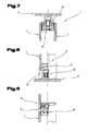
- both the floor construction and the ceiling construction are at least approximately symmetrical, as shown in FIGS. 6 and 7 show.
- a door element 6 is arranged.
- This door element 6 can be between two wall elements 2 - as can be seen from Fig. 1 - are arranged.
- the door element 6 itself can be room-high or it can be formed with a skylight - as known from the prior art.
- Fig. 8 shows a possibility of a ground connection for a door element 6 designed as a revolving door, which construction can be used both for the single-shell and the double-shell construction.
- the door element 6 in this case has a door frame 67, which in turn at the back, i. room inside (based on the separated space), a glass element 3 is glued to this.
- an upper part of the frame has a projecting leg 68 which extends at least approximately over the entire glass thickness of the glass element 3, corresponding to the angle 12 of the angle profile rail 11 of the floor construction 4 (FIG. 4).
- the lower area i.
- a rail element 69 is arranged, which essentially corresponds in its outer surface configuration to the profile rail 29 of the floor construction 4, with the exception that due to the rotatability of the door, this does not rise on the floor 8.
- a corresponding sealing element or brush element can be arranged between this rail element 69 and the bottom 8.
- a door frame against which the door frame of the revolving door strikes is preferably arranged on an adjacent glass wall 11 so that it is covered at least largely flur matter of this glass element 11, whereby the observer of the partition 1 in turn mainly the glass wall 11 faces.
- a variant of the revolving door is shown in which it has a skylight 70.
- the skylight 70 can according to the above with the in Fig. 9 Not shown ceiling construction 5 and the adjoining wall parts 2, ie glass elements 3 (Fig. 1) be connected.
- the revolving door, ie the upper door frame 67 is in turn glued to the back, ie room interior side, a glass element 3, wherein a part of this upper door frame 67 projects beyond the glass element 3 to abut against a stop 71 of the surface 70 connected to the part of the door frame is.
- a corresponding sealing element can be arranged between these two parts.
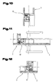
- Fig. 10 the upper stop of a revolving door with skylight 70 is shown for a two-shell construction, wherein the second rear glass element 3 of the skylight 70 shorter, i. less high, is formed so that the inside of the door frame 67 is completely visible.
- 11 and 12 show the lateral frame configurations of the revolving door, wherein these lateral frame parts are in turn glued surface-side superficially with the glass element 3 of the revolving door and against a corresponding stop, optionally formed with sealing element, stop.
- a part of the door frame 67 is projecting formed in the form of a Lisene.
- Fig. 11 also shows the arrangement of a handle set for the revolving door.
- the door element 6 can also be designed as a sliding door, as shown in FIG. 13 for a design with skylight 70.
- this top light 70 has through holes and, in addition to the guide rail 72 on the space inside back of the skylight 70, a corresponding support rail 73 is arranged, which via fasteners or screws the guide rail 72 is connected to rollers 74 of the sliding door. It is thus a secure grip and a corresponding ease of sliding door allows.
- the rollers 74 are connected to the door element 6, ie the sliding door, by means of screws 75, which are guided through corresponding bores of the glass element 3 of the sliding door. Of course, the rotation of the rollers 74 is ensured.
- the guide rail 72 and the retaining bar 73 arranged on the rear extend not only over the skylight 70, but via a wall element 2 arranged next to it in order to move the sliding door, i. to be able to push the door element 6, at least approximately completely, over the wall element 2 arranged next to it.
- Fig. 14 the embodiment of door element 6 is shown as a sliding door for a room-height variant of the partition 1.
- this ceiling construction 5 which corresponds to that according to FIG. 5, at the angle profile rail 60, which is connected to the ceiling construction 5 described above, a spacer 76, which may also be formed as a glass element, in the strength of the other glass elements 3 of the partition 1 and the guide rail 72 is arranged for the rollers 74 on the opposite side of this spacer elements 76, wherein the guide rail 72 in this embodiment, the angle rail 60, ie a leg thereof and thus also the spacer element, is formed across.
- the angle profile rail 60 may have a corresponding web 77 in said upper side of the ceiling 9, which engages in a groove 78 of the cross-section of the guide rail 72 in order to obtain a corresponding securing of the guide rail 72.
- the angle rail 60 is connected via corresponding holes or outlets in the spacer element 76 directly to the guide rail 72, for example screwed.
- FIG. 15 shows the bottom connection for a door element 6 designed as a sliding door.
- a profile with the glass element 3 via the adhesive tape 10, optionally with the interposition of glass blocks 13 between the glass element 3 and a leg 80 of the profile element 79 is arranged.
- a further part of the profile element 79 is formed projecting beyond the glass element 3 of the sliding door, which forms the lower end of the sliding door.
- a strip-shaped element 81 is arranged in a wall element 2 arranged next to it in the region of the lower profile element 79 in order to provide a stop for the profile element 79, after which the sliding door is designed to hang freely below to form and thus prevent damage to the opposite wall element.
- This profile element 79 thus forms the connecting rail for the sliding door.
- this linear damper which damps the linear movement of an element, too hard a stop of the sliding door can be damped in an end position and thus again damage can be prevented.
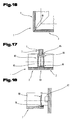
- Fig. 16 shows the formation of a 90 ° node or a 90 ° corner of two abutting glass elements 3 of the partition wall 1. This corner is cut mitred, between the abutting glass elements 3 preferably again an adhesive tape 10 or more adhesive tapes 10th of the type mentioned are arranged. It can of course be formed but also a silicone joint.
- Fig. 17 shows a possibility of forming a so-called T-terminal. By means of this T-connection, it is possible to separate further spaces within the space separated by the dividing wall 1.
- the T-connection provides a vertical profile element 82, which is adhesively bonded in each case to a part of the surface with the wall parts 2 arranged next to one another, so that, if appropriate, an expansion joint 83 is formed between these wall parts 2.
- the profile element 82 is another, at least approximately 90 ° thereto arranged wall element 2, for example, the glass element 3, attached to this profile element 82, for example, inserted into this, wherein the connection via corresponding sealing lips 84 can take place ,
- a core element 85 may be arranged in the interior of the profile element to improve the acoustic values, for example gypsum fiber boards or foam boards, which may also be glued to the profile element 82.
- skirt member 86 e.g. Flat rails, are inserted into corresponding groove-shaped recesses of the profile elements 82.
- the two strip elements 86 may e.g. made of ABS.
- FIG. 18 shows a possible wall connection for the single-shell construction, whereby this wall takes place via a wall connection element 87.
- a wall connection element 87 This may for example be a profile rail with a U-shaped cross-section or a corresponding square timber.
- a profile element 88 is used, which can be arranged on a further surface of the wall connection element 87 on that surface which is the surface - which is formed opposite to the wall -, this profile element 88 may be similar to the profile element 82, as Figs. 17 and 18 show comparative, so that the number of items required for the construction of the partition 1 can be reduced.
- Each profile element 88 can in turn be glued to the glass element 3 which adjoins the wall via an adhesive tape 10.
- FIGS. 19 and 20 show the construction of a T-connection or wall connection for the two-shell construction, it being apparent from these figures that the second shell of the wall part 2 is shorter, i.e. shorter, in space. not as wide as flur note, are formed and these glass elements 3 are arranged distanced to the profile elements 82 and 88, wherein for bridging this distance corresponding sealing elements 89 may be arranged.
- partition wall 1 therefore, an at least largely frameless or partition wall is made possible, which e.g. up to room heights up to 3.30 m without vertical profiles is available.
- the partition can be realized with the partition a puristic design and a maximum of technical possibilities.
- the flat surfaces allow for increased transparency.
- the characteristic lines on the floor and the ceiling are next to the technicality, as described above, and design feature of the partition 1.
- the partition thus allows maximum transparency and can also meet the requirements of fire protection and increased sound insulation.
- the visual perception of the glass surface allows the interior designer sophisticated office architecture.
- the wall elements or glass elements 3 are linearly mounted on the floor or ceiling construction 4,5.
- the module widths for example, widths in the range between 40 and 150 cm can be realized.
- the acoustic values can range between 36 dB and 42 or 48 and 50 dB.
Landscapes
- Engineering & Computer Science (AREA)
- Architecture (AREA)
- Civil Engineering (AREA)
- Structural Engineering (AREA)
- Physics & Mathematics (AREA)
- Electromagnetism (AREA)
- Floor Finish (AREA)
- Conveying And Assembling Of Building Elements In Situ (AREA)
Applications Claiming Priority (1)
| Application Number | Priority Date | Filing Date | Title |
|---|---|---|---|
| AT8222006A AT503531B1 (de) | 2006-05-12 | 2006-05-12 | Nivellierungsvorrichtung |
Publications (2)
| Publication Number | Publication Date |
|---|---|
| EP1854932A2 true EP1854932A2 (fr) | 2007-11-14 |
| EP1854932A3 EP1854932A3 (fr) | 2008-06-25 |
Family
ID=38293004
Family Applications (1)
| Application Number | Title | Priority Date | Filing Date |
|---|---|---|---|
| EP20070009295 Withdrawn EP1854932A3 (fr) | 2006-05-12 | 2007-05-09 | Dispositif de mise à niveau |
Country Status (2)
| Country | Link |
|---|---|
| EP (1) | EP1854932A3 (fr) |
| AT (1) | AT503531B1 (fr) |
Cited By (5)
| Publication number | Priority date | Publication date | Assignee | Title |
|---|---|---|---|---|
| ITMI20131962A1 (it) * | 2013-11-25 | 2015-05-26 | Tecno Spa | Struttura di telaio modulare |
| CN112523456A (zh) * | 2020-12-08 | 2021-03-19 | 浙江亚厦装饰股份有限公司 | 一种基层调平铝型材结构及安装方法 |
| US11655668B2 (en) | 2015-05-29 | 2023-05-23 | Overhead Door Corporation | Seamless multi-panel door |
| CN119434699A (zh) * | 2025-01-09 | 2025-02-14 | 广大住品科技发展有限公司 | 一种零动火无火花既有医疗建筑房屋改造工艺 |
| CN119905924A (zh) * | 2025-01-20 | 2025-04-29 | 华能海南发电股份有限公司南山电厂 | 一种开关柜制造组装预处理装置 |
Family Cites Families (9)
| Publication number | Priority date | Publication date | Assignee | Title |
|---|---|---|---|---|
| US2066718A (en) * | 1935-10-16 | 1937-01-05 | Louis F Dietz | Enclosure bulkhead |
| US3231054A (en) * | 1961-12-11 | 1966-01-25 | Birdsboro Corp | Adjustable support for partitions and curtain walls |
| DE1241966B (de) * | 1964-10-17 | 1967-06-08 | Reinhold Richter | Versetzbare Trennwand |
| CH436857A (de) * | 1966-01-14 | 1967-05-31 | Schrepfer Rudolf | Nivellierschuh |
| DE2264506A1 (de) * | 1972-07-22 | 1974-05-22 | Bertrams Ag Hch | Montagerahmen |
| DE3268993D1 (en) * | 1981-11-30 | 1986-03-20 | Bbc Brown Boveri & Cie | Screw drive for wedge |
| DE10124733A1 (de) * | 2001-05-21 | 2002-11-28 | Geze Glas Design Gmbh | Vorrichtung zur Höhenanpassung einer Trennwand |
| FR2863284B1 (fr) * | 2003-12-05 | 2007-11-23 | Placoplatre Sa | Dispositif pour le montage parasismique d'une cloison |
| EP1596019A3 (fr) * | 2004-05-14 | 2008-01-23 | Lindner Ag | Assemblage de cloison vitrée |
-
2006
- 2006-05-12 AT AT8222006A patent/AT503531B1/de not_active IP Right Cessation
-
2007
- 2007-05-09 EP EP20070009295 patent/EP1854932A3/fr not_active Withdrawn
Cited By (5)
| Publication number | Priority date | Publication date | Assignee | Title |
|---|---|---|---|---|
| ITMI20131962A1 (it) * | 2013-11-25 | 2015-05-26 | Tecno Spa | Struttura di telaio modulare |
| US11655668B2 (en) | 2015-05-29 | 2023-05-23 | Overhead Door Corporation | Seamless multi-panel door |
| CN112523456A (zh) * | 2020-12-08 | 2021-03-19 | 浙江亚厦装饰股份有限公司 | 一种基层调平铝型材结构及安装方法 |
| CN119434699A (zh) * | 2025-01-09 | 2025-02-14 | 广大住品科技发展有限公司 | 一种零动火无火花既有医疗建筑房屋改造工艺 |
| CN119905924A (zh) * | 2025-01-20 | 2025-04-29 | 华能海南发电股份有限公司南山电厂 | 一种开关柜制造组装预处理装置 |
Also Published As
| Publication number | Publication date |
|---|---|
| AT503531B1 (de) | 2013-11-15 |
| AT503531A1 (de) | 2007-11-15 |
| EP1854932A3 (fr) | 2008-06-25 |
Similar Documents
| Publication | Publication Date | Title |
|---|---|---|
| EP3423658B1 (fr) | Porte, fenêtre ou élément de façade | |
| DE102009044383A1 (de) | Morphologisches Modulsystem zur Erstellung von unterschiedlichen Gebäudeverschlüssen | |
| EP1854932A2 (fr) | Dispositif de mise à niveau | |
| CH653873A5 (de) | Duschtrennwand. | |
| EP2360340B2 (fr) | Installation de porte | |
| WO2008092699A1 (fr) | Dispositif d'inspection, en particulier élément de recouvrement d'inspection | |
| EP0918127B1 (fr) | Châssis de porte et dispositif de montage | |
| DE19719113C2 (de) | Türsystem | |
| DE2606645A1 (de) | Verbindungsvorrichtung fuer verkleidungspaneele oder trennwandelemente | |
| EP3293336B1 (fr) | Rail de retenue pour un balcon français ainsi que dispositif et système de retenue associés | |
| DE29508686U1 (de) | Bausatz zum Erstellen von Umkleidekabinen, Trennwänden u.dgl. | |
| EP3620603A1 (fr) | Système de montage pour murs | |
| EP1854955A2 (fr) | Paroi de séparation comprenant un élément en verre sans cadre | |
| DE19539014A1 (de) | Schiebetürbeschlag | |
| EP3168405B1 (fr) | Structure de châssis pour porte coulissante | |
| CH711428A2 (de) | Modulares System für Schränke und/oder Regale. | |
| DE69804669T2 (de) | Balkonverglasung | |
| DE102014202797B3 (de) | Distanzhalter | |
| EP2586928B1 (fr) | Support de plaque en particulier pour panneaux en verre | |
| DE102011121548A1 (de) | Befestigungselement,Befestigungsanordnung und Überdachung | |
| DE20101304U1 (de) | Von einer Wand geführtes Schiebetürelement und Aufhängung dafür | |
| DE202004010160U1 (de) | Universalprofil | |
| DE3224395A1 (de) | Teleskopierbarer beschlag fuer schiebetueren | |
| DE202018006481U1 (de) | Modulares Wandsystem | |
| DE10341828B4 (de) | Hohlprofilrahmen für eine Insektenschutztür |
Legal Events
| Date | Code | Title | Description |
|---|---|---|---|
| PUAI | Public reference made under article 153(3) epc to a published international application that has entered the european phase |
Free format text: ORIGINAL CODE: 0009012 |
|
| AK | Designated contracting states |
Kind code of ref document: A2 Designated state(s): AT BE BG CH CY CZ DE DK EE ES FI FR GB GR HU IE IS IT LI LT LU LV MC MT NL PL PT RO SE SI SK TR |
|
| AX | Request for extension of the european patent |
Extension state: AL BA HR MK YU |
|
| PUAL | Search report despatched |
Free format text: ORIGINAL CODE: 0009013 |
|
| AK | Designated contracting states |
Kind code of ref document: A3 Designated state(s): AT BE BG CH CY CZ DE DK EE ES FI FR GB GR HU IE IS IT LI LT LU LV MC MT NL PL PT RO SE SI SK TR |
|
| AX | Request for extension of the european patent |
Extension state: AL BA HR MK RS |
|
| 17P | Request for examination filed |
Effective date: 20081029 |
|
| AKX | Designation fees paid |
Designated state(s): AT BE BG CH CY CZ DE DK EE ES FI FR GB GR HU IE IS IT LI LT LU LV MC MT NL PL PT RO SE SI SK TR |
|
| AXX | Extension fees paid |
Extension state: RS Payment date: 20081029 Extension state: MK Payment date: 20081029 Extension state: HR Payment date: 20081029 Extension state: BA Payment date: 20081029 Extension state: AL Payment date: 20081029 |
|
| 17Q | First examination report despatched |
Effective date: 20100908 |
|
| 111Z | Information provided on other rights and legal means of execution |
Free format text: AT BE BG CH CY CZ DE DK EE ES FI FR GB GR HU IE IS IT LT LU LV MC MT NL PL PT RO SE SI SK TR Effective date: 20131106 |
|
| STAA | Information on the status of an ep patent application or granted ep patent |
Free format text: STATUS: THE APPLICATION IS DEEMED TO BE WITHDRAWN |
|
| 18D | Application deemed to be withdrawn |
Effective date: 20150721 |