EP1854965B1 - Joint à huile - Google Patents
Joint à huile Download PDFInfo
- Publication number
- EP1854965B1 EP1854965B1 EP07008832A EP07008832A EP1854965B1 EP 1854965 B1 EP1854965 B1 EP 1854965B1 EP 07008832 A EP07008832 A EP 07008832A EP 07008832 A EP07008832 A EP 07008832A EP 1854965 B1 EP1854965 B1 EP 1854965B1
- Authority
- EP
- European Patent Office
- Prior art keywords
- peripheral surface
- inner peripheral
- rubber
- oil seal
- metal ring
- Prior art date
- Legal status (The legal status is an assumption and is not a legal conclusion. Google has not performed a legal analysis and makes no representation as to the accuracy of the status listed.)
- Ceased
Links
Images

Classifications
-
- F—MECHANICAL ENGINEERING; LIGHTING; HEATING; WEAPONS; BLASTING
- F01—MACHINES OR ENGINES IN GENERAL; ENGINE PLANTS IN GENERAL; STEAM ENGINES
- F01L—CYCLICALLY OPERATING VALVES FOR MACHINES OR ENGINES
- F01L3/00—Lift-valve, i.e. cut-off apparatus with closure members having at least a component of their opening and closing motion perpendicular to the closing faces; Parts or accessories thereof
- F01L3/08—Valves guides; Sealing of valve stem, e.g. sealing by lubricant
-
- F—MECHANICAL ENGINEERING; LIGHTING; HEATING; WEAPONS; BLASTING
- F16—ENGINEERING ELEMENTS AND UNITS; GENERAL MEASURES FOR PRODUCING AND MAINTAINING EFFECTIVE FUNCTIONING OF MACHINES OR INSTALLATIONS; THERMAL INSULATION IN GENERAL
- F16J—PISTONS; CYLINDERS; SEALINGS
- F16J15/00—Sealings
- F16J15/16—Sealings between relatively-moving surfaces
- F16J15/32—Sealings between relatively-moving surfaces with elastic sealings, e.g. O-rings
- F16J15/3268—Mounting of sealing rings
- F16J15/3276—Mounting of sealing rings with additional static sealing between the sealing, or its casing or support, and the surface on which it is mounted
Definitions
- the present invention relates to an oil seal, one of sealing apparatuses, and more specifically relates to the oil seal suitable for use as a valve stem seal.
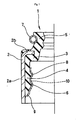
- valve stem oil seal 1 shown in Fig. 3 is known as a type of oil seal.
- This oil seal 1 is fitted into an outer peripheral side of a valve stem guide 21, which is a tubular attachment part, from one side (upside) in the axial direction, and is provided with a metal ring 2, and a rubber elastic body 3 deposited on this metal ring 2.
- the rubber elastic body 3 is provided with a rubber fitting part 4 deposited on an inner peripheral surface of the metal ring 2 and fitted into an outer peripheral surface of the valve stem guide 21, and a seal lip 5 closely contacted with a valve stem 22, which is a partner member, and wherein a protruded engaging part 6 engaging to a grooved engaging part 23 provided on the outer peripheral surface of the valve stem guide 21 is provided on an inner peripheral surface of the rubber fitting part 4 as a retainer of the oil seal 1.
- the rubber fitting part 4 is designed to allow an easy mounting to the valve stem guide 21 with a low fitting force, so that hand assembling (mounting by manual procedures) can be performed.
- the rubber fitting part 4 is designed to be mounted to the valve stem guide 21 with a low fitting force enabling hand mounting, at the same time however, due to the low fitting force (load), it is difficult to feel (hand-sensing) whether or not the oil seal 1 is securely mounted in the normal position (where the protruded engaging part 6 is fitted into the grooved engaging part 23).
- a follow-up visual inspection work for confirming whether or not the fitting part is securely mounted in the normal position is required, posing a problem that the mounting efficiency is compromised.
- the above described fitting force can be increased to enhance the sensing at the time of mounting, in such event however, the hand mounting itself becomes more difficult and therefore such approach can not be adopted.
- Patent Literature 1 Unexamined Japanese Patent Publication JP 11-350927 A .
- EP 0 352 118 A1 shows hydrodynamic shaft seals for use as rotary shaft seals.
- JP 59190575 A shows a low torque seal for rotary members.
- WO 2006/137182 A1 shows a seal in contact with a rotating shaft.
- FR 2 728 017 A shows an assembly comprising a metal ring comprising teeth.
- EP 1 092 841 A1 shows an assembly comprising a fitting part made of rubber.
- the present invention in consideration of the aforestated aspects, aims to provide an oil seal that allows to enhance the sensing at the time of hand mounting without increasing the fitting force required to mount the tubular attachment part, thereby the follow-up visual inspection work after the mounting can be eliminated.
- an oil seal according to claim 1 of this invention can be an oil seal fitted into an outer peripheral side of an tubular attachment part from one side in the axial direction, having a metal ring and a rubber elastic body deposited on said metal ring, wherein said rubber elastic body is provided with a rubber fitting part deposited on an inner peripheral surface of said metal ring and fitted into an outer peripheral surface of said tubular attachment part, and a seal lip closely contacted with a partner member, wherein a grooved engaging part engaging to a protruded engaging part provided on an outer peripheral surface of said tubular attachment part is provided on an inner peripheral surface of said rubber fitting part, and wherein a coating is applied over the inner peripheral surface of said rubber fitting part including said protruded engaging part.
- the assembly can be characterised in that the tubular attachment part is the valve stem guide, and that the said relevant oil seal is the valve stem oil seal that allows the seal lip to closely contact with the valve stem, in the oil seal as set forth in aforestated claim 1.
- the force (load) variation is gentle due to the rubbers elastic deformation, making it difficult to sense the variation by hand, on the contrary, according to the present invention, the force (load) greatly changes momentarily, making it easy to sense the variation by hand.
- the present invention produces the following effect.
- a coating is applied over the inner peripheral surface of the rubber fitting part including the protruded engaging part, thereby the coefficient of friction is reduced, and the rubber fitting part is surface hardened, thereby the force (load) difference (force (load) reduction amount) becomes greater upon when the protruded engaging part is fitted into the grooved engaging part, allowing the mounting feel ("JUST' feel) to be strongly felt.
- the follow-up visual inspection work after the mounting can be eliminated and the mounting efficiency can be improved.
- the fitting force thereof is not increased, thereby no deterioration in the mounting efficiency can occur.
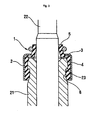
- Fig. 1 shows a half-cut drawing of the oil seal 1 according to the Example of this invention. Also, Fig. 2 shows a section in a mounted state.
- the oil seal 1 according to the said relevant Example is used as a valve stem oil seal, and is constituted as follows:
- the rubber elastic body 3 is deposited (vulcanization adhesion) on the metal ring 2 mounted to the outer peripheral side of the valve stem guide 21, which is a tubular attachment part, from one side (upside) in the axial direction, and through the use of this rubber elastic body 3, the rubber fitting part 4 deposited on the inner peripheral surface of the metal ring 2 and fitted into the outer peripheral surface of the valve stem guide 21, and the seal lip 5 slidably and closely contacted with a valve stem (not shown), which is a partner member, are formed together integrally.
- the metal ring 2 is formed by integrally molding an inward flange part 2b at the upper end of a tubular part 2a. Also, a spring (garter spring) 7 is attached by fitting into the seal lip 5.
- the protruded engaging part (projection) 6 axially engaging to the grooved engaging part 23 provided on the outer peripheral surface of the valve stem guide 21, is provided as a retainer of the oil seal 1, and a protruded seal part (projection) 8 is provided at the upside position thereof as a seal for the said relevant part.
- a tapered surface guide part 9 is provided at the lower end part of the rubber fitting part 4 in order to make the fitting process into the valve stem guide 21 easier, and furthermore, the rubber fitting part 4 as a whole is designed to be mounted to the valve stem guide 21 with a low fitting force.
- the PTFE coating 10 is applied over the inner peripheral surface of the rubber fitting part 4, due to the properties of the coating, the coefficient of friction is reduced, and at the same time, the inner peripheral surface of the rubber fitting part 4 is surface hardened, thereby, the instantaneous force (load) difference becomes greater upon when the protruded engaging part 6 is fitted into the grooved engaging part 23 allowing an operator to strongly feel the mounting feel ("JUST" feel).
- the follow-up visual inspection work after the mounting can be eliminated and the mounting efficiency can be improved.
- the fitting force thereof is not increased, thereby no deterioration in the mounting efficiency can occur.
- the PTFE coating 10 is applied over the approximately entire inner peripheral surface of the rubber fitting part 4 including the guide part 9, the protruded engaging part 6 and the protruded seal part 8, the coating may also be applied only over a part of the same inner peripheral surface as well. However, it is necessary the coating to be applied over the inner peripheral surface of the protruded engaging part 6 at minimum.
Landscapes
- Engineering & Computer Science (AREA)
- General Engineering & Computer Science (AREA)
- Mechanical Engineering (AREA)
- Sealing With Elastic Sealing Lips (AREA)
- Glass Compositions (AREA)
- Gasket Seals (AREA)
Claims (7)
- Ensemble comprenant un joint à huile (1) comprenant un anneau métallique (2) et un corps élastique en caoutchouc (3) déposé sur ledit anneau métallique (2), dans lequel ledit corps élastique en caoutchouc (3) comprend une partie d'emboîtement en caoutchouc (4) qui est déposée sur une surface périphérique intérieure dudit anneau métallique (2), une lèvre de joint (5) prévue pour entrer en contact intime avec un élément associé, et une partie d'engagement saillante (6) qui est prévue sur une surface périphérique intérieure de ladite partie d'emboîtement en caoutchouc (4), dans lequel le joint à huile (1) est emboîté dans un côté périphérique extérieur d'une partie de fixation tubulaire à partir d'un côté dans la direction axiale, tandis que la partie d'emboîtement (4) qui est déposée sur une surface périphérique intérieure dudit anneau métallique (2) est emboîtée dans une surface périphérique extérieure de ladite partie de fixation tubulaire, et la lèvre de joint (5) est placée en contact intime avec un élément associé, dans lequel la partie d'engagement saillante (6) qui s'engage dans une partie d'engagement rainurée (23) prévue sur la surface périphérique extérieure de ladite partie de fixation tubulaire est formée sur une surface périphérique intérieure de ladite partie d'emboîtement en caoutchouc (4),
caractérisé en ce qu'un revêtement (10) destiné à réduire le coefficient de friction est appliqué sur la surface périphérique intérieure de ladite partie d'engagement en caoutchouc (4) qui comporte ladite partie d'engagement saillante (6). - Ensemble selon la revendication 1, dans lequel le revêtement (10) est un revêtement de PTFE (10).
- Ensemble selon l'une quelconque des revendications 1 ou 2, dans lequel une partie de joint saillante (8) est prévue à une position supérieure de la partie d'engagement (6).
- Ensemble selon l'une quelconque des revendications 1 à 3, dans lequel une partie de guidage de surface conique (9) est prévue à la partie d'extrémité inférieure de la partie d'emboîtement en caoutchouc (4).
- Ensemble selon l'une quelconque des revendications 1 à 4, dans lequel un ressort (7) est attaché par emboîtement dans la lèvre de joint (5).
- Ensemble selon l'une quelconque des revendications 1 à 5, dans lequel l'anneau métallique (2) est formé en moulant intégralement une partie de bride intérieure (2b) à l'extrémité supérieure d'une partie tubulaire (2a).
- Ensemble selon l'une quelconque des revendications 1 à 6, dans lequel la partie de fixation tubulaire est un guide de tige de soupape (21), et ledit joint à huile (1) est un joint à huile de tige de soupape qui permet à la lèvre de joint (5) de se trouver en contact intime avec une tige de soupape.
Applications Claiming Priority (1)
| Application Number | Priority Date | Filing Date | Title |
|---|---|---|---|
| JP2006128134A JP2007298143A (ja) | 2006-05-02 | 2006-05-02 | オイルシール |
Publications (2)
| Publication Number | Publication Date |
|---|---|
| EP1854965A1 EP1854965A1 (fr) | 2007-11-14 |
| EP1854965B1 true EP1854965B1 (fr) | 2009-10-21 |
Family
ID=38521774
Family Applications (1)
| Application Number | Title | Priority Date | Filing Date |
|---|---|---|---|
| EP07008832A Ceased EP1854965B1 (fr) | 2006-05-02 | 2007-05-02 | Joint à huile |
Country Status (4)
| Country | Link |
|---|---|
| EP (1) | EP1854965B1 (fr) |
| JP (1) | JP2007298143A (fr) |
| AT (1) | ATE446441T1 (fr) |
| DE (1) | DE602007002838D1 (fr) |
Cited By (1)
| Publication number | Priority date | Publication date | Assignee | Title |
|---|---|---|---|---|
| CN115082675A (zh) * | 2022-06-07 | 2022-09-20 | 中南大学 | 一种透明物体图像分割方法及系统 |
Families Citing this family (10)
| Publication number | Priority date | Publication date | Assignee | Title |
|---|---|---|---|---|
| JP4788906B2 (ja) * | 2006-05-19 | 2011-10-05 | Nok株式会社 | バルブステムシール |
| JP2009264415A (ja) * | 2008-04-22 | 2009-11-12 | Nok Corp | バルブステムシールの装着構造 |
| JP5408443B2 (ja) * | 2010-03-02 | 2014-02-05 | Nok株式会社 | バルブステムシール |
| JP6384952B2 (ja) * | 2014-09-09 | 2018-09-05 | 株式会社ジェイテクト | 摺動部材 |
| JP6575606B2 (ja) * | 2015-12-08 | 2019-09-18 | Nok株式会社 | バルブステムシール |
| JP6677005B2 (ja) * | 2016-02-18 | 2020-04-08 | Nok株式会社 | バルブステムシール及び密封構造 |
| WO2018220031A1 (fr) * | 2017-06-02 | 2018-12-06 | Carl Freudenberg Kg | Bague d'étanchéité |
| JP2020041425A (ja) * | 2018-09-06 | 2020-03-19 | 株式会社デンソー | Egr用流量制御弁 |
| KR101992323B1 (ko) * | 2018-10-30 | 2019-06-25 | 평화오일씰공업 주식회사 | 더스트 씰 조립체 |
| KR102348131B1 (ko) * | 2019-09-04 | 2022-01-06 | 평화오일씰공업 주식회사 | 디링을 구비한 자동변속기 |
Family Cites Families (9)
| Publication number | Priority date | Publication date | Assignee | Title |
|---|---|---|---|---|
| JPS59190575A (ja) * | 1983-04-08 | 1984-10-29 | Nok Corp | 低トルクシ−ル |
| GB8323418D0 (en) * | 1983-09-01 | 1983-10-05 | Fenner Co Ltd J H | Valve stem seals |
| GB2220994B (en) * | 1988-07-21 | 1993-01-13 | Woodville Polymer Eng | Hydrodynamic shaft seals |
| JPH04104111U (ja) * | 1991-02-15 | 1992-09-08 | 株式会社荒井製作所 | バルブステムシール |
| US5553869A (en) * | 1994-12-12 | 1996-09-10 | Dana Corporation | Bonded valve stem seal with retainer tangs |
| JP2000081151A (ja) * | 1998-09-07 | 2000-03-21 | Koyo Seiko Co Ltd | オイルシール |
| DE19949248A1 (de) * | 1999-10-13 | 2001-04-19 | Freudenberg Carl Fa | Ventilschaftabdichtung |
| ITMI20010289A1 (it) * | 2001-02-13 | 2002-08-13 | Rft Spa | Guarnizione composita elastomero/ptfe in particolare per l'inserimento tra organi in rotazione relativa soggetti ad oscillazioni |
| US7789396B2 (en) * | 2005-06-21 | 2010-09-07 | Nok Corporation | Oil seal and process for producing the same |
-
2006
- 2006-05-02 JP JP2006128134A patent/JP2007298143A/ja active Pending
-
2007
- 2007-05-02 EP EP07008832A patent/EP1854965B1/fr not_active Ceased
- 2007-05-02 AT AT07008832T patent/ATE446441T1/de not_active IP Right Cessation
- 2007-05-02 DE DE602007002838T patent/DE602007002838D1/de active Active
Cited By (2)
| Publication number | Priority date | Publication date | Assignee | Title |
|---|---|---|---|---|
| CN115082675A (zh) * | 2022-06-07 | 2022-09-20 | 中南大学 | 一种透明物体图像分割方法及系统 |
| CN115082675B (zh) * | 2022-06-07 | 2024-06-04 | 中南大学 | 一种透明物体图像分割方法及系统 |
Also Published As
| Publication number | Publication date |
|---|---|
| DE602007002838D1 (de) | 2009-12-03 |
| ATE446441T1 (de) | 2009-11-15 |
| JP2007298143A (ja) | 2007-11-15 |
| EP1854965A1 (fr) | 2007-11-14 |
Similar Documents
| Publication | Publication Date | Title |
|---|---|---|
| EP1854965B1 (fr) | Joint à huile | |
| JP5041137B2 (ja) | 密封装置 | |
| CN105190084B (zh) | 用于封闭振动阻尼器的阻尼管的包封件 | |
| US9394998B2 (en) | Radial shaft seal assembly with snap in auxiliary member | |
| JP2011033187A (ja) | バルブステムシール | |
| JP5931453B2 (ja) | 転がり軸受 | |
| GB2517573A (en) | Dynamically non contacting seal | |
| US5865442A (en) | Lip-like seal | |
| US7942423B2 (en) | Lip type seal | |
| CA2496224A1 (fr) | Joint pour tube de bougie d'allumage | |
| CN212251132U (zh) | 密封装置 | |
| JP4743380B2 (ja) | オイルシール | |
| JP4123837B2 (ja) | バルブステムシール | |
| US11835136B2 (en) | Sealing device | |
| JP4788906B2 (ja) | バルブステムシール | |
| JP2006300204A (ja) | ボールジョイント | |
| JP4734712B2 (ja) | バルブステムシール | |
| JP4850787B2 (ja) | 密封装置 | |
| JP7224248B2 (ja) | 密封装置 | |
| JP2009127815A (ja) | 締付バンド | |
| US12578018B2 (en) | Steering dust seal and sealing device | |
| CN112013115B (zh) | 密封装置 | |
| JPH073089Y2 (ja) | 密封装置 | |
| JP2009068672A (ja) | 密封装置及びその製造方法 | |
| JP2005265078A (ja) | 密封装置 |
Legal Events
| Date | Code | Title | Description |
|---|---|---|---|
| PUAI | Public reference made under article 153(3) epc to a published international application that has entered the european phase |
Free format text: ORIGINAL CODE: 0009012 |
|
| AK | Designated contracting states |
Kind code of ref document: A1 Designated state(s): AT BE BG CH CY CZ DE DK EE ES FI FR GB GR HU IE IS IT LI LT LU LV MC MT NL PL PT RO SE SI SK TR |
|
| AX | Request for extension of the european patent |
Extension state: AL BA HR MK YU |
|
| 17P | Request for examination filed |
Effective date: 20080110 |
|
| 17Q | First examination report despatched |
Effective date: 20080207 |
|
| AKX | Designation fees paid |
Designated state(s): AT BE BG CH CY CZ DE DK EE ES FI FR GB GR HU IE IS IT LI LT LU LV MC MT NL PL PT RO SE SI SK TR |
|
| GRAP | Despatch of communication of intention to grant a patent |
Free format text: ORIGINAL CODE: EPIDOSNIGR1 |
|
| GRAS | Grant fee paid |
Free format text: ORIGINAL CODE: EPIDOSNIGR3 |
|
| GRAA | (expected) grant |
Free format text: ORIGINAL CODE: 0009210 |
|
| AK | Designated contracting states |
Kind code of ref document: B1 Designated state(s): AT BE BG CH CY CZ DE DK EE ES FI FR GB GR HU IE IS IT LI LT LU LV MC MT NL PL PT RO SE SI SK TR |
|
| REG | Reference to a national code |
Ref country code: GB Ref legal event code: FG4D |
|
| REG | Reference to a national code |
Ref country code: CH Ref legal event code: EP |
|
| REG | Reference to a national code |
Ref country code: IE Ref legal event code: FG4D |
|
| REF | Corresponds to: |
Ref document number: 602007002838 Country of ref document: DE Date of ref document: 20091203 Kind code of ref document: P |
|
| LTIE | Lt: invalidation of european patent or patent extension |
Effective date: 20091021 |
|
| REG | Reference to a national code |
Ref country code: NL Ref legal event code: VDEP Effective date: 20091021 |
|
| PG25 | Lapsed in a contracting state [announced via postgrant information from national office to epo] |
Ref country code: ES Free format text: LAPSE BECAUSE OF FAILURE TO SUBMIT A TRANSLATION OF THE DESCRIPTION OR TO PAY THE FEE WITHIN THE PRESCRIBED TIME-LIMIT Effective date: 20100201 Ref country code: IS Free format text: LAPSE BECAUSE OF FAILURE TO SUBMIT A TRANSLATION OF THE DESCRIPTION OR TO PAY THE FEE WITHIN THE PRESCRIBED TIME-LIMIT Effective date: 20100221 Ref country code: FI Free format text: LAPSE BECAUSE OF FAILURE TO SUBMIT A TRANSLATION OF THE DESCRIPTION OR TO PAY THE FEE WITHIN THE PRESCRIBED TIME-LIMIT Effective date: 20091021 Ref country code: LT Free format text: LAPSE BECAUSE OF FAILURE TO SUBMIT A TRANSLATION OF THE DESCRIPTION OR TO PAY THE FEE WITHIN THE PRESCRIBED TIME-LIMIT Effective date: 20091021 Ref country code: SE Free format text: LAPSE BECAUSE OF FAILURE TO SUBMIT A TRANSLATION OF THE DESCRIPTION OR TO PAY THE FEE WITHIN THE PRESCRIBED TIME-LIMIT Effective date: 20091021 Ref country code: PT Free format text: LAPSE BECAUSE OF FAILURE TO SUBMIT A TRANSLATION OF THE DESCRIPTION OR TO PAY THE FEE WITHIN THE PRESCRIBED TIME-LIMIT Effective date: 20100222 |
|
| PG25 | Lapsed in a contracting state [announced via postgrant information from national office to epo] |
Ref country code: SI Free format text: LAPSE BECAUSE OF FAILURE TO SUBMIT A TRANSLATION OF THE DESCRIPTION OR TO PAY THE FEE WITHIN THE PRESCRIBED TIME-LIMIT Effective date: 20091021 Ref country code: PL Free format text: LAPSE BECAUSE OF FAILURE TO SUBMIT A TRANSLATION OF THE DESCRIPTION OR TO PAY THE FEE WITHIN THE PRESCRIBED TIME-LIMIT Effective date: 20091021 Ref country code: LV Free format text: LAPSE BECAUSE OF FAILURE TO SUBMIT A TRANSLATION OF THE DESCRIPTION OR TO PAY THE FEE WITHIN THE PRESCRIBED TIME-LIMIT Effective date: 20091021 |
|
| PG25 | Lapsed in a contracting state [announced via postgrant information from national office to epo] |
Ref country code: AT Free format text: LAPSE BECAUSE OF FAILURE TO SUBMIT A TRANSLATION OF THE DESCRIPTION OR TO PAY THE FEE WITHIN THE PRESCRIBED TIME-LIMIT Effective date: 20091021 Ref country code: BE Free format text: LAPSE BECAUSE OF FAILURE TO SUBMIT A TRANSLATION OF THE DESCRIPTION OR TO PAY THE FEE WITHIN THE PRESCRIBED TIME-LIMIT Effective date: 20091021 |
|
| PG25 | Lapsed in a contracting state [announced via postgrant information from national office to epo] |
Ref country code: DK Free format text: LAPSE BECAUSE OF FAILURE TO SUBMIT A TRANSLATION OF THE DESCRIPTION OR TO PAY THE FEE WITHIN THE PRESCRIBED TIME-LIMIT Effective date: 20091021 Ref country code: EE Free format text: LAPSE BECAUSE OF FAILURE TO SUBMIT A TRANSLATION OF THE DESCRIPTION OR TO PAY THE FEE WITHIN THE PRESCRIBED TIME-LIMIT Effective date: 20091021 Ref country code: BG Free format text: LAPSE BECAUSE OF FAILURE TO SUBMIT A TRANSLATION OF THE DESCRIPTION OR TO PAY THE FEE WITHIN THE PRESCRIBED TIME-LIMIT Effective date: 20100121 Ref country code: RO Free format text: LAPSE BECAUSE OF FAILURE TO SUBMIT A TRANSLATION OF THE DESCRIPTION OR TO PAY THE FEE WITHIN THE PRESCRIBED TIME-LIMIT Effective date: 20091021 Ref country code: NL Free format text: LAPSE BECAUSE OF FAILURE TO SUBMIT A TRANSLATION OF THE DESCRIPTION OR TO PAY THE FEE WITHIN THE PRESCRIBED TIME-LIMIT Effective date: 20091021 |
|
| PLBE | No opposition filed within time limit |
Free format text: ORIGINAL CODE: 0009261 |
|
| STAA | Information on the status of an ep patent application or granted ep patent |
Free format text: STATUS: NO OPPOSITION FILED WITHIN TIME LIMIT |
|
| PG25 | Lapsed in a contracting state [announced via postgrant information from national office to epo] |
Ref country code: SK Free format text: LAPSE BECAUSE OF FAILURE TO SUBMIT A TRANSLATION OF THE DESCRIPTION OR TO PAY THE FEE WITHIN THE PRESCRIBED TIME-LIMIT Effective date: 20091021 Ref country code: CZ Free format text: LAPSE BECAUSE OF FAILURE TO SUBMIT A TRANSLATION OF THE DESCRIPTION OR TO PAY THE FEE WITHIN THE PRESCRIBED TIME-LIMIT Effective date: 20091021 |
|
| 26N | No opposition filed |
Effective date: 20100722 |
|
| PG25 | Lapsed in a contracting state [announced via postgrant information from national office to epo] |
Ref country code: GR Free format text: LAPSE BECAUSE OF FAILURE TO SUBMIT A TRANSLATION OF THE DESCRIPTION OR TO PAY THE FEE WITHIN THE PRESCRIBED TIME-LIMIT Effective date: 20100122 |
|
| PG25 | Lapsed in a contracting state [announced via postgrant information from national office to epo] |
Ref country code: MC Free format text: LAPSE BECAUSE OF NON-PAYMENT OF DUE FEES Effective date: 20100531 |
|
| PG25 | Lapsed in a contracting state [announced via postgrant information from national office to epo] |
Ref country code: IT Free format text: LAPSE BECAUSE OF NON-PAYMENT OF DUE FEES Effective date: 20100502 |
|
| PG25 | Lapsed in a contracting state [announced via postgrant information from national office to epo] |
Ref country code: IE Free format text: LAPSE BECAUSE OF NON-PAYMENT OF DUE FEES Effective date: 20100502 Ref country code: MT Free format text: LAPSE BECAUSE OF FAILURE TO SUBMIT A TRANSLATION OF THE DESCRIPTION OR TO PAY THE FEE WITHIN THE PRESCRIBED TIME-LIMIT Effective date: 20091021 |
|
| REG | Reference to a national code |
Ref country code: CH Ref legal event code: PL |
|
| PG25 | Lapsed in a contracting state [announced via postgrant information from national office to epo] |
Ref country code: LI Free format text: LAPSE BECAUSE OF NON-PAYMENT OF DUE FEES Effective date: 20110531 Ref country code: CH Free format text: LAPSE BECAUSE OF NON-PAYMENT OF DUE FEES Effective date: 20110531 |
|
| PG25 | Lapsed in a contracting state [announced via postgrant information from national office to epo] |
Ref country code: CY Free format text: LAPSE BECAUSE OF FAILURE TO SUBMIT A TRANSLATION OF THE DESCRIPTION OR TO PAY THE FEE WITHIN THE PRESCRIBED TIME-LIMIT Effective date: 20091021 |
|
| PG25 | Lapsed in a contracting state [announced via postgrant information from national office to epo] |
Ref country code: LU Free format text: LAPSE BECAUSE OF NON-PAYMENT OF DUE FEES Effective date: 20100502 Ref country code: HU Free format text: LAPSE BECAUSE OF FAILURE TO SUBMIT A TRANSLATION OF THE DESCRIPTION OR TO PAY THE FEE WITHIN THE PRESCRIBED TIME-LIMIT Effective date: 20100422 |
|
| PG25 | Lapsed in a contracting state [announced via postgrant information from national office to epo] |
Ref country code: TR Free format text: LAPSE BECAUSE OF FAILURE TO SUBMIT A TRANSLATION OF THE DESCRIPTION OR TO PAY THE FEE WITHIN THE PRESCRIBED TIME-LIMIT Effective date: 20091021 |
|
| REG | Reference to a national code |
Ref country code: FR Ref legal event code: PLFP Year of fee payment: 10 |
|
| REG | Reference to a national code |
Ref country code: FR Ref legal event code: PLFP Year of fee payment: 11 |
|
| REG | Reference to a national code |
Ref country code: FR Ref legal event code: PLFP Year of fee payment: 12 |
|
| PGFP | Annual fee paid to national office [announced via postgrant information from national office to epo] |
Ref country code: IT Payment date: 20220531 Year of fee payment: 16 Ref country code: GB Payment date: 20220522 Year of fee payment: 16 Ref country code: FR Payment date: 20220520 Year of fee payment: 16 Ref country code: DE Payment date: 20220602 Year of fee payment: 16 |
|
| REG | Reference to a national code |
Ref country code: DE Ref legal event code: R119 Ref document number: 602007002838 Country of ref document: DE |
|
| GBPC | Gb: european patent ceased through non-payment of renewal fee |
Effective date: 20230502 |
|
| PG25 | Lapsed in a contracting state [announced via postgrant information from national office to epo] |
Ref country code: DE Free format text: LAPSE BECAUSE OF NON-PAYMENT OF DUE FEES Effective date: 20231201 Ref country code: GB Free format text: LAPSE BECAUSE OF NON-PAYMENT OF DUE FEES Effective date: 20230502 |
|
| PG25 | Lapsed in a contracting state [announced via postgrant information from national office to epo] |
Ref country code: FR Free format text: LAPSE BECAUSE OF NON-PAYMENT OF DUE FEES Effective date: 20230531 |
|
| PG25 | Lapsed in a contracting state [announced via postgrant information from national office to epo] |
Ref country code: IT Free format text: LAPSE BECAUSE OF NON-PAYMENT OF DUE FEES Effective date: 20230502 |