EP1856760B1 - Anordnung und verfahren zur drucküberwachung in einer batteriezelle - Google Patents
Anordnung und verfahren zur drucküberwachung in einer batteriezelle Download PDFInfo
- Publication number
- EP1856760B1 EP1856760B1 EP06710677A EP06710677A EP1856760B1 EP 1856760 B1 EP1856760 B1 EP 1856760B1 EP 06710677 A EP06710677 A EP 06710677A EP 06710677 A EP06710677 A EP 06710677A EP 1856760 B1 EP1856760 B1 EP 1856760B1
- Authority
- EP
- European Patent Office
- Prior art keywords
- strain gauge
- cell
- battery cell
- processing unit
- battery
- Prior art date
- Legal status (The legal status is an assumption and is not a legal conclusion. Google has not performed a legal analysis and makes no representation as to the accuracy of the status listed.)
- Expired - Lifetime
Links
Images




Classifications
-
- H—ELECTRICITY
- H01—ELECTRIC ELEMENTS
- H01M—PROCESSES OR MEANS, e.g. BATTERIES, FOR THE DIRECT CONVERSION OF CHEMICAL ENERGY INTO ELECTRICAL ENERGY
- H01M10/00—Secondary cells; Manufacture thereof
- H01M10/42—Methods or arrangements for servicing or maintenance of secondary cells or secondary half-cells
- H01M10/425—Structural combination with electronic components, e.g. electronic circuits integrated to the outside of the casing
-
- H—ELECTRICITY
- H01—ELECTRIC ELEMENTS
- H01M—PROCESSES OR MEANS, e.g. BATTERIES, FOR THE DIRECT CONVERSION OF CHEMICAL ENERGY INTO ELECTRICAL ENERGY
- H01M10/00—Secondary cells; Manufacture thereof
- H01M10/42—Methods or arrangements for servicing or maintenance of secondary cells or secondary half-cells
- H01M10/44—Methods for charging or discharging
- H01M10/445—Methods for charging or discharging in response to gas pressure
-
- H—ELECTRICITY
- H01—ELECTRIC ELEMENTS
- H01M—PROCESSES OR MEANS, e.g. BATTERIES, FOR THE DIRECT CONVERSION OF CHEMICAL ENERGY INTO ELECTRICAL ENERGY
- H01M10/00—Secondary cells; Manufacture thereof
- H01M10/42—Methods or arrangements for servicing or maintenance of secondary cells or secondary half-cells
- H01M10/48—Accumulators combined with arrangements for measuring, testing or indicating the condition of cells, e.g. the level or density of the electrolyte
-
- H—ELECTRICITY
- H01—ELECTRIC ELEMENTS
- H01M—PROCESSES OR MEANS, e.g. BATTERIES, FOR THE DIRECT CONVERSION OF CHEMICAL ENERGY INTO ELECTRICAL ENERGY
- H01M10/00—Secondary cells; Manufacture thereof
- H01M10/42—Methods or arrangements for servicing or maintenance of secondary cells or secondary half-cells
- H01M10/48—Accumulators combined with arrangements for measuring, testing or indicating the condition of cells, e.g. the level or density of the electrolyte
- H01M10/482—Accumulators combined with arrangements for measuring, testing or indicating the condition of cells, e.g. the level or density of the electrolyte for several batteries or cells simultaneously or sequentially
-
- H—ELECTRICITY
- H01—ELECTRIC ELEMENTS
- H01M—PROCESSES OR MEANS, e.g. BATTERIES, FOR THE DIRECT CONVERSION OF CHEMICAL ENERGY INTO ELECTRICAL ENERGY
- H01M10/00—Secondary cells; Manufacture thereof
- H01M10/42—Methods or arrangements for servicing or maintenance of secondary cells or secondary half-cells
- H01M10/44—Methods for charging or discharging
- H01M10/448—End of discharge regulating measures
-
- Y—GENERAL TAGGING OF NEW TECHNOLOGICAL DEVELOPMENTS; GENERAL TAGGING OF CROSS-SECTIONAL TECHNOLOGIES SPANNING OVER SEVERAL SECTIONS OF THE IPC; TECHNICAL SUBJECTS COVERED BY FORMER USPC CROSS-REFERENCE ART COLLECTIONS [XRACs] AND DIGESTS
- Y02—TECHNOLOGIES OR APPLICATIONS FOR MITIGATION OR ADAPTATION AGAINST CLIMATE CHANGE
- Y02E—REDUCTION OF GREENHOUSE GAS [GHG] EMISSIONS, RELATED TO ENERGY GENERATION, TRANSMISSION OR DISTRIBUTION
- Y02E60/00—Enabling technologies; Technologies with a potential or indirect contribution to GHG emissions mitigation
- Y02E60/10—Energy storage using batteries
Definitions
- the invention relates to an arrangement for monitoring pressure within a battery cell, comprising: at least one battery cell, and at least one strain gauge for monitoring mechanical deformation of the battery cell, said strain gauge being at least partially wound around a cell casing of said battery cell.
- the invention also relates to a method of monitoring internal pressure of a battery cell, comprising the step of: A) measuring the mechanical deformation of a battery cell by at least one strain gauge attached to an outer surface of a cell casing of said battery.
- Battery monitor systems measure and collect the status of the battery and display results.
- Battery management systems control the charge phase and partly the discharge phase, based on measurements.
- the measurement values are often parameters of mathematical models describing the status of the battery. These models form the basis for control programs of microprocessor-based battery monitor and management systems.
- Important physical values that should be collected in a battery are current, voltage, temperature and pressure. The latter three are specifically important for the modelling of multi-cell batteries if the physical value can be measured per cell.
- United States Patent US 5,694,018 discloses an assembly of a battery charging compartment and a battery positioned in said compartment, wherein the battery compartment is provided with a strain gauge for unilaterally monitoring the deformation of the battery introduced by elevated pressure within the battery (and partially the temperature introduced expansion) to activate a simple mechanical switch. Thereby the charging current is interrupted. It is also proposed to use a bridge measuring the expansion for the electrical determination of the mechanical deformation.
- this known arrangement has multiple drawbacks. A major drawback of this known arrangement will be elucidated hereinafter.
- United States Patent Application 2002/0119364 discloses an assembly of an arrangement according to the preamble and a charger, wherein a processor of said charger can be electrically connected to the strain gauge of the battery during charging.
- An important drawback of this known assembly is that monitoring the battery pressure is merely possible during charging by the charger. It is an object of the invention to provide an improved arrangement for monitoring the actual internal pressure of a battery cell more accurately.
- This object can be achieved by providing an arrangement according to the preamble, characterized in that said strain gauge is electronically coupled to a processing unit attached to the cell casing for processing the mechanical deformation monitored by the strain gauge.
- said processing unit is relatively small, and may be formed by a small chip incorporating an electronic circuit.
- the change of the effective coil area leads to a change of the AC- and RF-parameters of the coil, and in particular to a change of the inductivity. These changes can be observed as complex impedance. It is also proposed to observe the resonance behaviour of the electronic circuit, including the, preferably coil-shaped, strain gauge. This resonance behaviour will change due to the change of the coil dimensions.
- said processing unit is adapted to communicate, preferably wirelessly, with an external device, such as a battery management system.
- Battery management systems control the charge phase and partly the discharge phase, based on measurements as mentioned above.
- the strain gauge preferably formed by a measurement line, is in intensive contact with the battery cell of which the internal pressure is monitored. In this manner, the pressure built up within the battery cell can be monitored relatively carefully through the (elastic) deformation, in particular stretching or changing of the winding area, of the strain gauge.
- said strain gauge is at least partially wound helically around said cell casing.
- said strain gauge is preferably at least substantially coil-shaped to be able to cover the cell casing in an optimal way. In this way a slight deformation in a - possibly present - weaker part of the cell casing can be detected relatively quickly and precisely. In fact, stretching of the windings changes the ohmic resistance of the strain gauge.
- the change of the geometry can be observed relatively precisely, if the recent measurement is compared to the measurement of the non-stretched lines.
- the strain gauge should preferably be made of appropriate materials, for example materials with a stable specific resistance, independent of temperature variances. Since the strain gauge is applied to an outer surface of the cell casing, there is no direct contact between the strain gauge and the chemical reactants within the cell casing. For this reason, corrosion of the strain gauge will not occur under normal conditions, which gives the arrangement according to the invention an advantageous durability.
- the processing unit comprises a calibration arrangement.
- the calibration arrangement can also be part of an external device, such as a microprocessor supporting control unit.
- the pressure measurement values will be stored of well-defined conditions and states of the battery cells. For example the starting conditions of a non-aged, well-charged or non-loaded cell can be stored as calibration values, assuming non-increased pressure values.
- calibration values can be related to cell temperature or cell voltage.
- the measurement line can be used also as a loop or coil antenna for wireless communication with the cell sensor. Typically, these functions do not interact, since different frequencies are used for communication and pressure measurement.
- said processing unit is powered by means of induced electricity. However, it is also conceivable that said processing unit is powered by the battery cell.
- said strain gauge is also adapted for use as an antenna to allow the processing unit to communicate with the external device. At high frequencies, the reduction of the number of windings, in the extreme to a single loop, could be suitable. This is especially necessary if the antenna needs to be effective at higher communication frequencies.
- the pressure values in addition to other parameters like cell voltage and temperature, will be used for electronic switching within the battery.
- the pressure strain gauge can be connected in such a way that it can be used as a bypass line to prevent overcharging of the battery cell by passing a fraction of the charging current around the battery cell.
- said battery cell comprises an outer hull, wherein the strain gauge is substantially positioned between the cell casing and the outer hull. In this manner the strain gauge is protected by a shielding cover which is formed by the, preferably elastic, hull. In this way, the strain gauge is positioned in a covered manner within the boundaries of the battery cell.
- said arrangement comprises multiple battery cells, wherein the strain gauge is at least partially wound around the cell casing of each battery cell. It is imaginable to apply multiple strain gauges, wherein each strain gauge could be wound around a respective battery cell. If a group of cells is observed with a joint strain gauge, the sensing arrangement should preferably be able to detect an overpressure condition of any individual cell forming part of that group.
- the invention also relates to a method of monitoring pressure within a battery cell according to the preamble, characterized in that the method further comprising the steps of: B) processing the mechanical deformation monitored by the strain gauge by means of a processing unit electronically coupled to said strain gauge to obtain pressure related data, and C) allowing the processing unit to communicate with an external device for wireless transmission of the pressure related data from the processing unit to said external device.
- communication between the processing unit and the external device according to step C) is realized by means of the strain gauge acting as antenna.
- Figure 1 shows a coil-shaped measurement line around the cell jacket of a cylindrical cell 1, comprising a cell jacket 3 around which a measurement line 2 is wound in a coil-shaped manner.
- One end of the measurement line 2 is connected to a cell sensor 4.
- the other end of the measurement line 2 is connected to a pole 5 of the cell 1.
- the cell jacket 3 is located within an elastic outer hull 6, for example a sleeve made from soft plastics or foam plastic.
- the cell 1 should allow expansion of the mechanical dimensions of the cell during pressure generation within the cell 1.
- Figure 2 shows the deformation of the measurement line 2 shown in Figure 1 due to a pressure rise in the cell 1.
- the expanded barrel-shaped cell jacket 3 is shown. It is expanded within the elastic outer hull 6.
- the coil 2 has its maximum enlargement of the diameter in the middle of the cell 1. Due to this fact, the circumference (the length of the measurement line) and the effective area of the coil 2 have been enlarged to a maximum, resulting in changed physical properties of the measurement line 2 which can be monitored by the sensor 4.
- FIG 3 shows another preferred embodiment of an arrangement 7 according to the invention.
- the arrangement 7 comprises two measurement lines 8, 9 which are wound helically around two respective cylindrical cells 10, 11.
- the measurement lines 8, 9 are mutually connected by means of a single cell sensor 12.
- the upper cell 10 and the lower cell 11 are connected in series.
- the respective measurement lines 8, 9 are connected to opposite poles 13, 14 of the cells 10, 11.
- the cell sensor 12 observes the group of cells 10, 11.
- the upper measurement line 8 leads from the upper pole 13 of the upper cell 10 to the sensor 12.
- a further measurement line 9 leads from the opposite pole 14 of the lower cell 11 to the cell sensor 12.
- Both measurement lines 8, 9 are coil-shaped and surround the jackets of both cells 10, 11.
- Both cells 10, 11 are located in a single, sleeve-shaped, elastic outer hull 15 for the group of cells 10, 11, which allows expansion without remarkable forces.
- the battery compartment (not shown) in which the arrangement is positioned also should not influence the expansion by remarkable forces.
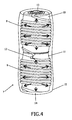
- Figure 4 shows the deformation of the arrangement 7 shown in Figure 3 due to a pressure rise.
- the measurement lines 8, 9 are deformed due to the barrel-shaped expansion of the cells 10, 11, which can be monitored by the cell sensor 12.
- the monitored deformation gives an indication of the internal pressure and thus of the state of the cells 10, 11.
- Figure 5 shows another arrangement 16 according to the invention in a normal state.
- the arrangement 16 comprises a group of substantially parallel-oriented cylindrical cells 17 bundled together by means of a coil-shaped measurement line 18.
- the measurement line 18 is connected to a sensor circuit 19 to monitor deformation of the cells 17 due to a pressure rise.
- the arrangement 16 is encapsulated by an elastically deformable outer hull 20.
- Figure 6 shows the arrangement 16 as shown in Figure 5 in an expanded state due to a pressure rise within one or more cells 17.
- the bundle of cells 17 have been subjected to a barrel-shaped deformation. Due to the deformation of the cells 17, the measurement line 18 is stretched. This stretching and the intensity of stretching of the measurement line 18 can be detected by the sensor cell 19.
- These pressure-related data can subsequently be transmitted wirelessly to a battery management system, which is, for example, incorporated in a battery charger (not shown).
- a battery management system which is, for example, incorporated in a battery charger (not shown).
- Dependent on the (over)pressure detected in the cells 17 appropriate action, for example switching off, can be taken by the battery charger.
Landscapes
- Engineering & Computer Science (AREA)
- Manufacturing & Machinery (AREA)
- Chemical & Material Sciences (AREA)
- Chemical Kinetics & Catalysis (AREA)
- Electrochemistry (AREA)
- General Chemical & Material Sciences (AREA)
- Microelectronics & Electronic Packaging (AREA)
- Secondary Cells (AREA)
- Measuring Fluid Pressure (AREA)
Claims (12)
- Anordnung zur Drucküberwachung in einer Batteriezelle, mit:mindestens einer Batteriezelle undmindestens einem Dehnungsmesser zur Überwachung mechanischer Verformung der Batteriezelle, wobei der Dehnungsmesser zumindest teilweise um ein Zellengehäuse der Batteriezelle gewickelt ist,dadurch gekennzeichnet, dass der Dehnungsmesser an eine an dem Zellengehäuse angebrachte Verarbeitungseinheit elektronisch gekoppelt ist, um die von dem Dehnungsmesser überwachte, mechanische Verformung zu verarbeiten.
- Anordnung nach Anspruch 1, dadurch gekennzeichnet, dass der Dehnungsmesser zumindest teilweise spiralförmig um das Zellengehäuse gewickelt ist.
- Anordnung nach Anspruch w, dadurch gekennzeichnet, dass der Dehnungsmesser zumindest im Wesentlichen spulenförmig ist.
- Anordnung nach einem der vorangegangenen Ansprüche, dadurch gekennzeichnet, dass die Verarbeitungseinheit so eingerichtet ist, dass sie mit einer externen Einrichtung kommuniziert.
- Anordnung nach Anspruch 4, dadurch gekennzeichnet, dass die Verarbeitungseinheit so eingerichtet ist, dass sie mit der externen Einrichtung drahtlos kommuniziert.
- Anordnung nach einem der vorangegangenen Ansprüche, dadurch gekennzeichnet, dass die Verarbeitungseinheit mit Hilfe induzierter Elektrizität gespeist wird.
- Anordnung nach einem der vorangegangenen Ansprüche, dadurch gekennzeichnet, dass die Verarbeitungseinheit von der Batteriezelle gespeist wird.
- Anordnung nach Anspruch 4 oder 5, dadurch gekennzeichnet, dass der Dehnungsmesser ebenfalls zur Verwendung als eine Antenne eingerichtet ist, damit die Verarbeitungseinheit mit der externen Einrichtung kommunizieren kann.
- Anordnung nach einem der vorangegangenen Ansprüche, dadurch gekennzeichnet, dass die Batteriezelle eine äußere Hülle umfasst, wobei der Dehnungsmesser im Wesentlichen zwischen dem Zellengehäuse und der äußeren Hülle platziert ist.
- Anordnung nach einem der vorangegangenen Ansprüche, dadurch gekennzeichnet, dass die Anordnung mehrere Batteriezellen umfasst, wobei der Dehnungsmesser zumindest teilweise um das Zellengehäuse jeder Batteriezelle gewickelt ist.
- Verfahren zur Drucküberwachung in einer Batteriezelle, wonach
die mechanische Verformung einer Batteriezelle von mindestens einem Dehnungsmesser, der an einer Außenfläche eines Zellengehäuses der Batterie angebracht ist, gemessen wird,
dadurch gekennzeichnet, dass das Verfahren weiterhin Schritte umfasst, wonach:die von dem Dehnungsmesser überwachte, mechanische Verformung mit Hilfe einer Verarbeitungseinheit, die an den Dehnungsmesser elektronisch gekoppelt ist, um druckbezogene Daten zu erhalten, verarbeitet wird, unddie Verarbeitungseinheit mit einer externen Einrichtung zur drahtlosen Übertragung der druckbezogenen Daten von der Verarbeitungseinheit zu der externen Einrichtung kommunizieren kann. - Verfahren nach Anspruch 11, dadurch gekennzeichnet, dass Kommunikation zwischen der Verarbeitungseinheit und der externen Einrichtung gemäß Schritt C) mit Hilfe des als Antenne wirkenden Dehnungsmessers realisiert wird.
Priority Applications (1)
| Application Number | Priority Date | Filing Date | Title |
|---|---|---|---|
| EP06710677A EP1856760B1 (de) | 2005-01-20 | 2006-01-16 | Anordnung und verfahren zur drucküberwachung in einer batteriezelle |
Applications Claiming Priority (3)
| Application Number | Priority Date | Filing Date | Title |
|---|---|---|---|
| EP05100335 | 2005-01-20 | ||
| EP06710677A EP1856760B1 (de) | 2005-01-20 | 2006-01-16 | Anordnung und verfahren zur drucküberwachung in einer batteriezelle |
| PCT/IB2006/050148 WO2006077519A1 (en) | 2005-01-20 | 2006-01-16 | Arrangement and method for monitoring pressure within a battery cell |
Publications (2)
| Publication Number | Publication Date |
|---|---|
| EP1856760A1 EP1856760A1 (de) | 2007-11-21 |
| EP1856760B1 true EP1856760B1 (de) | 2010-03-17 |
Family
ID=34938538
Family Applications (1)
| Application Number | Title | Priority Date | Filing Date |
|---|---|---|---|
| EP06710677A Expired - Lifetime EP1856760B1 (de) | 2005-01-20 | 2006-01-16 | Anordnung und verfahren zur drucküberwachung in einer batteriezelle |
Country Status (7)
| Country | Link |
|---|---|
| US (1) | US20080097704A1 (de) |
| EP (1) | EP1856760B1 (de) |
| JP (1) | JP2008529213A (de) |
| CN (1) | CN100533845C (de) |
| AT (1) | ATE461535T1 (de) |
| DE (1) | DE602006012940D1 (de) |
| WO (1) | WO2006077519A1 (de) |
Cited By (2)
| Publication number | Priority date | Publication date | Assignee | Title |
|---|---|---|---|---|
| EP4135095A1 (de) * | 2021-08-10 | 2023-02-15 | Volvo Car Corporation | Überwachungssystem für ein energiespeichersystem |
| EP3796460B1 (de) * | 2018-05-15 | 2023-10-04 | Samsung SDI Co., Ltd. | Batteriepack |
Families Citing this family (40)
| Publication number | Priority date | Publication date | Assignee | Title |
|---|---|---|---|---|
| EP1983803A1 (de) | 2007-04-17 | 2008-10-22 | Oticon A/S | Steueranordnung für Hörgeräte oder für an Hörgeräte gekoppelte Steuereinheiten |
| KR20090009598A (ko) * | 2007-07-20 | 2009-01-23 | 경상대학교산학협력단 | 무선 충전용 선형 전지 |
| US10923776B2 (en) * | 2007-12-31 | 2021-02-16 | Apple Inc. | Systems and methods for monitoring and responding to forces influencing a battery |
| JP5444762B2 (ja) * | 2008-07-02 | 2014-03-19 | トヨタ自動車株式会社 | 圧力測定装置及び厚み測定装置 |
| US8399115B2 (en) * | 2009-02-04 | 2013-03-19 | Bayerische Motoren Werke Aktiengesellschaft | System and apparatus for monitoring large battery stacks using wireless sensor networks |
| US8269610B2 (en) * | 2009-10-23 | 2012-09-18 | The Goodyear Tire & Rubber Company | Method for measuring pressure in a tire |
| US8395519B2 (en) | 2010-11-19 | 2013-03-12 | General Electric Company | Device and method of determining safety in a battery pack |
| JP5609859B2 (ja) * | 2011-12-21 | 2014-10-22 | トヨタ自動車株式会社 | 電池システム |
| CN102610870A (zh) * | 2012-03-27 | 2012-07-25 | 奇瑞汽车股份有限公司 | 一种方型动力锂离子电池及其保护方法 |
| DE102012209397A1 (de) * | 2012-06-04 | 2013-12-05 | Robert Bosch Gmbh | Batteriezelle mit drucksensitivem Foliensensor |
| CN103018681B (zh) * | 2012-12-19 | 2015-04-15 | 上海交通大学 | 基于任意形状电池芯的形变检测电动车电池寿命衰退及安全状态的技术 |
| US9660299B2 (en) | 2013-12-10 | 2017-05-23 | Southwest Research Institute | Strain measurement based battery testing |
| CN104296911A (zh) * | 2014-01-17 | 2015-01-21 | 中航锂电(洛阳)有限公司 | 一种锂离子电池电芯受力测定方法及装置 |
| US10270137B1 (en) | 2014-04-04 | 2019-04-23 | Olaeris, Inc. | Battery status and failure detector |
| US9356325B1 (en) * | 2015-01-22 | 2016-05-31 | Ford Global Technologies, Llc | Electrified vehicle battery pack monitoring assembly and method |
| EP3054523A1 (de) * | 2015-02-04 | 2016-08-10 | Siemens Aktiengesellschaft | Speichervorrichtung mit wenigstens einer elektrochemischen Energiespeicherzelle sowie Verfahren zum Überwachen einer solchen Speichervorrichtung |
| US10120035B2 (en) | 2015-12-01 | 2018-11-06 | Southwest Research Institute | Monitoring and control of electrochemical cell degradation via strain based battery testing |
| CN106959093B (zh) * | 2016-01-08 | 2020-11-03 | 中兴通讯股份有限公司 | 一种电池形变检测方法及设备 |
| DE102016206671A1 (de) * | 2016-04-20 | 2017-10-26 | Robert Bosch Gmbh | Längenausdehnungsüberwachung zur Bestimmung der Alterung einer Batteriezelle oder eines Batteriemoduls |
| CN107607872A (zh) * | 2016-07-12 | 2018-01-19 | 中兴通讯股份有限公司 | 一种电池检测设备、电池检测方法和装置 |
| CN106338691A (zh) * | 2016-08-25 | 2017-01-18 | 合肥国轩高科动力能源有限公司 | 一种电池安全测试过程中的压力检测装置 |
| CN106960984A (zh) * | 2017-02-16 | 2017-07-18 | 上海与德通讯技术有限公司 | 电池、终端及电池保护方法 |
| KR102379479B1 (ko) * | 2017-03-10 | 2022-03-28 | 삼성전자 주식회사 | 기압 기반 배터리 상태 결정 방법 및 전자 장치 |
| JP6864536B2 (ja) * | 2017-04-25 | 2021-04-28 | 株式会社東芝 | 二次電池システム、充電方法、プログラム、及び車両 |
| US10714795B2 (en) * | 2017-05-01 | 2020-07-14 | Infineon Technologies Ag | Monitoring battery cell internal pressure |
| CN108063286B (zh) * | 2017-11-10 | 2020-09-11 | 浙江衡远新能源科技有限公司 | 一种用于电池组电芯膨胀的检测装置及动力电池包 |
| CN108955990B (zh) * | 2018-04-19 | 2020-12-11 | 东南大学 | 一种实时监测模拟环境中血管支架径向支撑力的实验装置 |
| CN108445416B (zh) * | 2018-04-28 | 2020-09-01 | 北京新能源汽车股份有限公司 | 一种电池失效检测系统、方法、装置及汽车 |
| CN111596213B (zh) * | 2019-02-20 | 2021-10-08 | 江苏师范大学 | 电池状态监控专用的电阻膜 |
| CN111600086B (zh) * | 2019-02-20 | 2021-07-20 | 江苏师范大学 | Led应急灯的电池鼓包检测模块 |
| CN110208711B (zh) * | 2019-05-15 | 2021-04-16 | 天津力神电池股份有限公司 | 用于在线测试圆柱电池充放电过程中极片受力情况的方法 |
| WO2020242476A1 (en) * | 2019-05-30 | 2020-12-03 | Google Llc | Methods to continuously monitor battery cell physical health and swell |
| DE102019005317A1 (de) | 2019-07-30 | 2021-02-04 | Hochschule für Angewandte Wissenschaften Hamburg (HAW Hamburg) | Verfahren und Anordnungen zur Erkennung des Ladezustandes von Lithium-lonen-Batterien mit optischen Mitteln |
| KR20220076472A (ko) * | 2019-10-08 | 2022-06-08 | 제이티 인터내셔널 소시에떼 아노님 | 배터리 모니터링 장치를 갖는 에어로졸 발생 장치 |
| KR102721572B1 (ko) * | 2020-03-12 | 2024-10-23 | 주식회사 엘지에너지솔루션 | 배터리 셀의 스웰링 검사 장치 |
| CN217786150U (zh) * | 2022-05-05 | 2022-11-11 | 宁德时代新能源科技股份有限公司 | 应变检测组件、电池以及用电设备 |
| CN117183818A (zh) * | 2022-05-30 | 2023-12-08 | 比亚迪半导体股份有限公司 | 一种电芯管理芯片、电池系统、车辆 |
| WO2024144899A1 (en) * | 2022-12-30 | 2024-07-04 | VLTRU Systems, LLC | Pressure sensors and circuits for preventing battery fires, and applications thereof |
| GB2633348A (en) * | 2023-09-06 | 2025-03-12 | Schlumberger Technology Bv | Measuring attachment for batteries |
| CN120049033A (zh) * | 2023-11-27 | 2025-05-27 | 空中客车(中国)企业管理服务有限公司 | 电池单元、电池单元制造方法、航空电池及航空电池的监测方法 |
Family Cites Families (13)
| Publication number | Priority date | Publication date | Assignee | Title |
|---|---|---|---|---|
| US4564798A (en) * | 1982-10-06 | 1986-01-14 | Escutcheon Associates | Battery performance control |
| JPS63268445A (ja) * | 1987-04-24 | 1988-11-07 | Nec Home Electronics Ltd | ニツケル・カドミウム2次電池の急速充電方法 |
| JPH081678B2 (ja) * | 1990-05-02 | 1996-01-10 | 株式会社日立製作所 | 2線式計測回路 |
| JPH10502767A (ja) * | 1995-04-28 | 1998-03-10 | フィリップス エレクトロニクス ネムローゼ フェンノートシャップ | バッテリ再充電装置 |
| JP3736853B2 (ja) * | 1995-04-30 | 2006-01-18 | コーニンクレッカ フィリップス エレクトロニクス エヌ ヴィ | バッテリ再充電装置 |
| WO1996035252A1 (en) * | 1995-04-30 | 1996-11-07 | Philips Electronics N.V. | Apparatus for charging a battery |
| US5963012A (en) * | 1998-07-13 | 1999-10-05 | Motorola, Inc. | Wireless battery charging system having adaptive parameter sensing |
| DE19936063B4 (de) * | 1999-07-30 | 2004-03-04 | Cochlear Ltd., Lane Cove | Elektrochemische Sekundärzelle |
| JP2004517440A (ja) * | 2000-10-20 | 2004-06-10 | レイオバック コーポレイション | 電気化学セルの充電を調整する方法及び装置 |
| US7592776B2 (en) * | 2001-11-07 | 2009-09-22 | Quallion Llc | Energy storage device configured to discharge energy in response to unsafe conditions |
| US6891353B2 (en) * | 2001-11-07 | 2005-05-10 | Quallion Llc | Safety method, device and system for an energy storage device |
| AU2003274571A1 (en) * | 2002-11-15 | 2004-06-15 | Koninklijke Philips Electronics N.V. | Wireless battery management system |
| US7972738B2 (en) * | 2006-10-18 | 2011-07-05 | Olympus Imaging Corp. | Residual capacity detection method and residual capacity detection system for fuel cell battery |
-
2006
- 2006-01-16 DE DE602006012940T patent/DE602006012940D1/de not_active Expired - Lifetime
- 2006-01-16 AT AT06710677T patent/ATE461535T1/de not_active IP Right Cessation
- 2006-01-16 WO PCT/IB2006/050148 patent/WO2006077519A1/en not_active Ceased
- 2006-01-16 EP EP06710677A patent/EP1856760B1/de not_active Expired - Lifetime
- 2006-01-16 JP JP2007551777A patent/JP2008529213A/ja active Pending
- 2006-01-16 US US11/814,096 patent/US20080097704A1/en not_active Abandoned
- 2006-01-16 CN CNB2006800027012A patent/CN100533845C/zh not_active Expired - Fee Related
Cited By (3)
| Publication number | Priority date | Publication date | Assignee | Title |
|---|---|---|---|---|
| EP3796460B1 (de) * | 2018-05-15 | 2023-10-04 | Samsung SDI Co., Ltd. | Batteriepack |
| EP4135095A1 (de) * | 2021-08-10 | 2023-02-15 | Volvo Car Corporation | Überwachungssystem für ein energiespeichersystem |
| US12030404B2 (en) | 2021-08-10 | 2024-07-09 | Volvo Car Corporation | Monitoring system for an energy storage system |
Also Published As
| Publication number | Publication date |
|---|---|
| ATE461535T1 (de) | 2010-04-15 |
| WO2006077519A1 (en) | 2006-07-27 |
| CN100533845C (zh) | 2009-08-26 |
| US20080097704A1 (en) | 2008-04-24 |
| EP1856760A1 (de) | 2007-11-21 |
| JP2008529213A (ja) | 2008-07-31 |
| DE602006012940D1 (de) | 2010-04-29 |
| CN101107747A (zh) | 2008-01-16 |
Similar Documents
| Publication | Publication Date | Title |
|---|---|---|
| US20080097704A1 (en) | Arrangement and Method for Monitoring Pressure within a Battery Cell | |
| JP5914694B2 (ja) | バッテリー | |
| CN107305973B (zh) | 用于确定电池组电池或电池组模块的老化的长度伸展监控 | |
| CN103201889B (zh) | 二次电池单体、电池组以及电力消耗装置 | |
| CN217719732U (zh) | 一种电池安全监测装置及电池 | |
| US20030038611A1 (en) | Rechargeable batteries | |
| US9847560B2 (en) | Electrochemical energy cell, and rechargeable battery for repeatedly storing electrical energy, and also method for determining an electrode potential of an electrode of an electrochemical energy storage cell | |
| US9509020B1 (en) | Volumetric battery health sensor | |
| KR101881091B1 (ko) | 합금으로 만들어진 음극을 포함하는 리튬 이온 셀이 완전히 충전되는 때를 결정하는 방법, 이와 결부된 셀 및 배터리 | |
| CN109860735A (zh) | 机械放大式蓄电池单元压力传感器 | |
| JP2018522387A (ja) | 電池セルのハウジングの内部の圧力を決定する方法、及び、電池セル | |
| EP4618232A1 (de) | Abdeckplattenanordnung, batterie, energiespeichervorrichtung und stromverbrauchende vorrichtung | |
| KR102447552B1 (ko) | 이차 전지 상태 검출 장치 | |
| KR20200099364A (ko) | 배터리 셀 이상 판단 장치 및 방법 | |
| CN115911620A (zh) | 电池监测装置及电池装置 | |
| JP2019145342A (ja) | 診断装置及び制御装置 | |
| CN215731875U (zh) | 锂离子电池及锂离子电池监控系统 | |
| JP2003187879A (ja) | 電池監視装置及び充電装置 | |
| JP2014514693A (ja) | 電流遮断装置を有する電気化学的エネルギー貯蔵セル | |
| JP2022146693A (ja) | 温度測定方法、温度測定装置、及び電池システム | |
| US11469455B2 (en) | Battery monitoring systems having conductive strips and related methods | |
| CN104659401B (zh) | 蓄电元件以及蓄电元件模块 | |
| CN112762806A (zh) | 一种健康度自测的智慧锂电池 | |
| CN114597337B (zh) | 一种电池极片以及动力电池 | |
| KR102812317B1 (ko) | 온도 측정 모듈 및 이를 포함하는 배터리 팩 |
Legal Events
| Date | Code | Title | Description |
|---|---|---|---|
| PUAI | Public reference made under article 153(3) epc to a published international application that has entered the european phase |
Free format text: ORIGINAL CODE: 0009012 |
|
| 17P | Request for examination filed |
Effective date: 20070820 |
|
| AK | Designated contracting states |
Kind code of ref document: A1 Designated state(s): AT BE BG CH CY CZ DE DK EE ES FI FR GB GR HU IE IS IT LI LT LU LV MC NL PL PT RO SE SI SK TR |
|
| DAX | Request for extension of the european patent (deleted) | ||
| 17Q | First examination report despatched |
Effective date: 20080417 |
|
| RAP1 | Party data changed (applicant data changed or rights of an application transferred) |
Owner name: PHILIPS INTELLECTUAL PROPERTY & STANDARDS GMBH Owner name: KONINKLIJKE PHILIPS ELECTRONICS N.V. |
|
| GRAP | Despatch of communication of intention to grant a patent |
Free format text: ORIGINAL CODE: EPIDOSNIGR1 |
|
| GRAS | Grant fee paid |
Free format text: ORIGINAL CODE: EPIDOSNIGR3 |
|
| GRAA | (expected) grant |
Free format text: ORIGINAL CODE: 0009210 |
|
| AK | Designated contracting states |
Kind code of ref document: B1 Designated state(s): AT BE BG CH CY CZ DE DK EE ES FI FR GB GR HU IE IS IT LI LT LU LV MC NL PL PT RO SE SI SK TR |
|
| REG | Reference to a national code |
Ref country code: GB Ref legal event code: FG4D |
|
| REG | Reference to a national code |
Ref country code: CH Ref legal event code: EP |
|
| REG | Reference to a national code |
Ref country code: IE Ref legal event code: FG4D |
|
| REF | Corresponds to: |
Ref document number: 602006012940 Country of ref document: DE Date of ref document: 20100429 Kind code of ref document: P |
|
| REG | Reference to a national code |
Ref country code: NL Ref legal event code: VDEP Effective date: 20100317 |
|
| PG25 | Lapsed in a contracting state [announced via postgrant information from national office to epo] |
Ref country code: LT Free format text: LAPSE BECAUSE OF FAILURE TO SUBMIT A TRANSLATION OF THE DESCRIPTION OR TO PAY THE FEE WITHIN THE PRESCRIBED TIME-LIMIT Effective date: 20100317 |
|
| LTIE | Lt: invalidation of european patent or patent extension |
Effective date: 20100317 |
|
| PG25 | Lapsed in a contracting state [announced via postgrant information from national office to epo] |
Ref country code: PL Free format text: LAPSE BECAUSE OF FAILURE TO SUBMIT A TRANSLATION OF THE DESCRIPTION OR TO PAY THE FEE WITHIN THE PRESCRIBED TIME-LIMIT Effective date: 20100317 Ref country code: LV Free format text: LAPSE BECAUSE OF FAILURE TO SUBMIT A TRANSLATION OF THE DESCRIPTION OR TO PAY THE FEE WITHIN THE PRESCRIBED TIME-LIMIT Effective date: 20100317 Ref country code: FI Free format text: LAPSE BECAUSE OF FAILURE TO SUBMIT A TRANSLATION OF THE DESCRIPTION OR TO PAY THE FEE WITHIN THE PRESCRIBED TIME-LIMIT Effective date: 20100317 Ref country code: AT Free format text: LAPSE BECAUSE OF FAILURE TO SUBMIT A TRANSLATION OF THE DESCRIPTION OR TO PAY THE FEE WITHIN THE PRESCRIBED TIME-LIMIT Effective date: 20100317 Ref country code: SI Free format text: LAPSE BECAUSE OF FAILURE TO SUBMIT A TRANSLATION OF THE DESCRIPTION OR TO PAY THE FEE WITHIN THE PRESCRIBED TIME-LIMIT Effective date: 20100317 |
|
| PG25 | Lapsed in a contracting state [announced via postgrant information from national office to epo] |
Ref country code: RO Free format text: LAPSE BECAUSE OF FAILURE TO SUBMIT A TRANSLATION OF THE DESCRIPTION OR TO PAY THE FEE WITHIN THE PRESCRIBED TIME-LIMIT Effective date: 20100317 Ref country code: NL Free format text: LAPSE BECAUSE OF FAILURE TO SUBMIT A TRANSLATION OF THE DESCRIPTION OR TO PAY THE FEE WITHIN THE PRESCRIBED TIME-LIMIT Effective date: 20100317 Ref country code: BE Free format text: LAPSE BECAUSE OF FAILURE TO SUBMIT A TRANSLATION OF THE DESCRIPTION OR TO PAY THE FEE WITHIN THE PRESCRIBED TIME-LIMIT Effective date: 20100317 Ref country code: CY Free format text: LAPSE BECAUSE OF FAILURE TO SUBMIT A TRANSLATION OF THE DESCRIPTION OR TO PAY THE FEE WITHIN THE PRESCRIBED TIME-LIMIT Effective date: 20100317 Ref country code: EE Free format text: LAPSE BECAUSE OF FAILURE TO SUBMIT A TRANSLATION OF THE DESCRIPTION OR TO PAY THE FEE WITHIN THE PRESCRIBED TIME-LIMIT Effective date: 20100317 Ref country code: ES Free format text: LAPSE BECAUSE OF FAILURE TO SUBMIT A TRANSLATION OF THE DESCRIPTION OR TO PAY THE FEE WITHIN THE PRESCRIBED TIME-LIMIT Effective date: 20100628 Ref country code: SE Free format text: LAPSE BECAUSE OF FAILURE TO SUBMIT A TRANSLATION OF THE DESCRIPTION OR TO PAY THE FEE WITHIN THE PRESCRIBED TIME-LIMIT Effective date: 20100317 Ref country code: GR Free format text: LAPSE BECAUSE OF FAILURE TO SUBMIT A TRANSLATION OF THE DESCRIPTION OR TO PAY THE FEE WITHIN THE PRESCRIBED TIME-LIMIT Effective date: 20100618 |
|
| PG25 | Lapsed in a contracting state [announced via postgrant information from national office to epo] |
Ref country code: IS Free format text: LAPSE BECAUSE OF FAILURE TO SUBMIT A TRANSLATION OF THE DESCRIPTION OR TO PAY THE FEE WITHIN THE PRESCRIBED TIME-LIMIT Effective date: 20100717 Ref country code: BG Free format text: LAPSE BECAUSE OF FAILURE TO SUBMIT A TRANSLATION OF THE DESCRIPTION OR TO PAY THE FEE WITHIN THE PRESCRIBED TIME-LIMIT Effective date: 20100617 Ref country code: CZ Free format text: LAPSE BECAUSE OF FAILURE TO SUBMIT A TRANSLATION OF THE DESCRIPTION OR TO PAY THE FEE WITHIN THE PRESCRIBED TIME-LIMIT Effective date: 20100317 Ref country code: SK Free format text: LAPSE BECAUSE OF FAILURE TO SUBMIT A TRANSLATION OF THE DESCRIPTION OR TO PAY THE FEE WITHIN THE PRESCRIBED TIME-LIMIT Effective date: 20100317 |
|
| PLBE | No opposition filed within time limit |
Free format text: ORIGINAL CODE: 0009261 |
|
| STAA | Information on the status of an ep patent application or granted ep patent |
Free format text: STATUS: NO OPPOSITION FILED WITHIN TIME LIMIT |
|
| PG25 | Lapsed in a contracting state [announced via postgrant information from national office to epo] |
Ref country code: DK Free format text: LAPSE BECAUSE OF FAILURE TO SUBMIT A TRANSLATION OF THE DESCRIPTION OR TO PAY THE FEE WITHIN THE PRESCRIBED TIME-LIMIT Effective date: 20100317 Ref country code: PT Free format text: LAPSE BECAUSE OF FAILURE TO SUBMIT A TRANSLATION OF THE DESCRIPTION OR TO PAY THE FEE WITHIN THE PRESCRIBED TIME-LIMIT Effective date: 20100719 |
|
| 26N | No opposition filed |
Effective date: 20101220 |
|
| PG25 | Lapsed in a contracting state [announced via postgrant information from national office to epo] |
Ref country code: IT Free format text: LAPSE BECAUSE OF FAILURE TO SUBMIT A TRANSLATION OF THE DESCRIPTION OR TO PAY THE FEE WITHIN THE PRESCRIBED TIME-LIMIT Effective date: 20100317 |
|
| PG25 | Lapsed in a contracting state [announced via postgrant information from national office to epo] |
Ref country code: MC Free format text: LAPSE BECAUSE OF NON-PAYMENT OF DUE FEES Effective date: 20110131 |
|
| REG | Reference to a national code |
Ref country code: CH Ref legal event code: PL |
|
| GBPC | Gb: european patent ceased through non-payment of renewal fee |
Effective date: 20110116 |
|
| REG | Reference to a national code |
Ref country code: FR Ref legal event code: ST Effective date: 20110930 |
|
| REG | Reference to a national code |
Ref country code: IE Ref legal event code: MM4A |
|
| PG25 | Lapsed in a contracting state [announced via postgrant information from national office to epo] |
Ref country code: LI Free format text: LAPSE BECAUSE OF NON-PAYMENT OF DUE FEES Effective date: 20110131 Ref country code: CH Free format text: LAPSE BECAUSE OF NON-PAYMENT OF DUE FEES Effective date: 20110131 Ref country code: FR Free format text: LAPSE BECAUSE OF NON-PAYMENT OF DUE FEES Effective date: 20110131 |
|
| PG25 | Lapsed in a contracting state [announced via postgrant information from national office to epo] |
Ref country code: GB Free format text: LAPSE BECAUSE OF NON-PAYMENT OF DUE FEES Effective date: 20110116 |
|
| REG | Reference to a national code |
Ref country code: DE Ref legal event code: R119 Ref document number: 602006012940 Country of ref document: DE Effective date: 20110802 |
|
| PG25 | Lapsed in a contracting state [announced via postgrant information from national office to epo] |
Ref country code: IE Free format text: LAPSE BECAUSE OF NON-PAYMENT OF DUE FEES Effective date: 20110116 |
|
| PG25 | Lapsed in a contracting state [announced via postgrant information from national office to epo] |
Ref country code: LU Free format text: LAPSE BECAUSE OF NON-PAYMENT OF DUE FEES Effective date: 20110116 |
|
| PG25 | Lapsed in a contracting state [announced via postgrant information from national office to epo] |
Ref country code: DE Free format text: LAPSE BECAUSE OF NON-PAYMENT OF DUE FEES Effective date: 20110802 |
|
| PG25 | Lapsed in a contracting state [announced via postgrant information from national office to epo] |
Ref country code: TR Free format text: LAPSE BECAUSE OF FAILURE TO SUBMIT A TRANSLATION OF THE DESCRIPTION OR TO PAY THE FEE WITHIN THE PRESCRIBED TIME-LIMIT Effective date: 20100317 |
|
| PG25 | Lapsed in a contracting state [announced via postgrant information from national office to epo] |
Ref country code: HU Free format text: LAPSE BECAUSE OF FAILURE TO SUBMIT A TRANSLATION OF THE DESCRIPTION OR TO PAY THE FEE WITHIN THE PRESCRIBED TIME-LIMIT Effective date: 20100317 |