EP1857320B1 - Sicherheitssitzvorrichtung für Wagen - Google Patents
Sicherheitssitzvorrichtung für Wagen Download PDFInfo
- Publication number
- EP1857320B1 EP1857320B1 EP06010449A EP06010449A EP1857320B1 EP 1857320 B1 EP1857320 B1 EP 1857320B1 EP 06010449 A EP06010449 A EP 06010449A EP 06010449 A EP06010449 A EP 06010449A EP 1857320 B1 EP1857320 B1 EP 1857320B1
- Authority
- EP
- European Patent Office
- Prior art keywords
- frame unit
- rod
- cylinders
- cylinder
- car
- Prior art date
- Legal status (The legal status is an assumption and is not a legal conclusion. Google has not performed a legal analysis and makes no representation as to the accuracy of the status listed.)
- Expired - Lifetime
Links
Images








Classifications
-
- B—PERFORMING OPERATIONS; TRANSPORTING
- B60—VEHICLES IN GENERAL
- B60N—SEATS SPECIALLY ADAPTED FOR VEHICLES; VEHICLE PASSENGER ACCOMMODATION NOT OTHERWISE PROVIDED FOR
- B60N2/00—Seats specially adapted for vehicles; Arrangement or mounting of seats in vehicles
- B60N2/24—Seats specially adapted for vehicles; Arrangement or mounting of seats in vehicles for particular purposes or particular vehicles
- B60N2/42—Seats specially adapted for vehicles; Arrangement or mounting of seats in vehicles for particular purposes or particular vehicles the seat constructed to protect the occupant from the effect of abnormal g-forces, e.g. crash or safety seats
- B60N2/427—Seats or parts thereof displaced during a crash
- B60N2/42727—Seats or parts thereof displaced during a crash involving substantially rigid displacement
- B60N2/42736—Seats or parts thereof displaced during a crash involving substantially rigid displacement of the whole seat
-
- B—PERFORMING OPERATIONS; TRANSPORTING
- B60—VEHICLES IN GENERAL
- B60N—SEATS SPECIALLY ADAPTED FOR VEHICLES; VEHICLE PASSENGER ACCOMMODATION NOT OTHERWISE PROVIDED FOR
- B60N2/00—Seats specially adapted for vehicles; Arrangement or mounting of seats in vehicles
- B60N2/80—Head-rests
- B60N2/888—Head-rests with arrangements for protecting against abnormal g-forces, e.g. by displacement of the head-rest
-
- B—PERFORMING OPERATIONS; TRANSPORTING
- B60—VEHICLES IN GENERAL
- B60N—SEATS SPECIALLY ADAPTED FOR VEHICLES; VEHICLE PASSENGER ACCOMMODATION NOT OTHERWISE PROVIDED FOR
- B60N2/00—Seats specially adapted for vehicles; Arrangement or mounting of seats in vehicles
- B60N2/24—Seats specially adapted for vehicles; Arrangement or mounting of seats in vehicles for particular purposes or particular vehicles
- B60N2/42—Seats specially adapted for vehicles; Arrangement or mounting of seats in vehicles for particular purposes or particular vehicles the seat constructed to protect the occupant from the effect of abnormal g-forces, e.g. crash or safety seats
- B60N2/4207—Seats specially adapted for vehicles; Arrangement or mounting of seats in vehicles for particular purposes or particular vehicles the seat constructed to protect the occupant from the effect of abnormal g-forces, e.g. crash or safety seats characterised by the direction of the g-forces
- B60N2/4214—Seats specially adapted for vehicles; Arrangement or mounting of seats in vehicles for particular purposes or particular vehicles the seat constructed to protect the occupant from the effect of abnormal g-forces, e.g. crash or safety seats characterised by the direction of the g-forces longitudinal
- B60N2/4221—Seats specially adapted for vehicles; Arrangement or mounting of seats in vehicles for particular purposes or particular vehicles the seat constructed to protect the occupant from the effect of abnormal g-forces, e.g. crash or safety seats characterised by the direction of the g-forces longitudinal due to impact coming from the front
-
- B—PERFORMING OPERATIONS; TRANSPORTING
- B60—VEHICLES IN GENERAL
- B60N—SEATS SPECIALLY ADAPTED FOR VEHICLES; VEHICLE PASSENGER ACCOMMODATION NOT OTHERWISE PROVIDED FOR
- B60N2/00—Seats specially adapted for vehicles; Arrangement or mounting of seats in vehicles
- B60N2/24—Seats specially adapted for vehicles; Arrangement or mounting of seats in vehicles for particular purposes or particular vehicles
- B60N2/42—Seats specially adapted for vehicles; Arrangement or mounting of seats in vehicles for particular purposes or particular vehicles the seat constructed to protect the occupant from the effect of abnormal g-forces, e.g. crash or safety seats
- B60N2/4207—Seats specially adapted for vehicles; Arrangement or mounting of seats in vehicles for particular purposes or particular vehicles the seat constructed to protect the occupant from the effect of abnormal g-forces, e.g. crash or safety seats characterised by the direction of the g-forces
- B60N2/4214—Seats specially adapted for vehicles; Arrangement or mounting of seats in vehicles for particular purposes or particular vehicles the seat constructed to protect the occupant from the effect of abnormal g-forces, e.g. crash or safety seats characterised by the direction of the g-forces longitudinal
- B60N2/4228—Seats specially adapted for vehicles; Arrangement or mounting of seats in vehicles for particular purposes or particular vehicles the seat constructed to protect the occupant from the effect of abnormal g-forces, e.g. crash or safety seats characterised by the direction of the g-forces longitudinal due to impact coming from the rear
-
- B—PERFORMING OPERATIONS; TRANSPORTING
- B60—VEHICLES IN GENERAL
- B60N—SEATS SPECIALLY ADAPTED FOR VEHICLES; VEHICLE PASSENGER ACCOMMODATION NOT OTHERWISE PROVIDED FOR
- B60N2/00—Seats specially adapted for vehicles; Arrangement or mounting of seats in vehicles
- B60N2/24—Seats specially adapted for vehicles; Arrangement or mounting of seats in vehicles for particular purposes or particular vehicles
- B60N2/42—Seats specially adapted for vehicles; Arrangement or mounting of seats in vehicles for particular purposes or particular vehicles the seat constructed to protect the occupant from the effect of abnormal g-forces, e.g. crash or safety seats
- B60N2/4207—Seats specially adapted for vehicles; Arrangement or mounting of seats in vehicles for particular purposes or particular vehicles the seat constructed to protect the occupant from the effect of abnormal g-forces, e.g. crash or safety seats characterised by the direction of the g-forces
- B60N2/4235—Seats specially adapted for vehicles; Arrangement or mounting of seats in vehicles for particular purposes or particular vehicles the seat constructed to protect the occupant from the effect of abnormal g-forces, e.g. crash or safety seats characterised by the direction of the g-forces transversal
-
- B—PERFORMING OPERATIONS; TRANSPORTING
- B60—VEHICLES IN GENERAL
- B60N—SEATS SPECIALLY ADAPTED FOR VEHICLES; VEHICLE PASSENGER ACCOMMODATION NOT OTHERWISE PROVIDED FOR
- B60N2/00—Seats specially adapted for vehicles; Arrangement or mounting of seats in vehicles
- B60N2/24—Seats specially adapted for vehicles; Arrangement or mounting of seats in vehicles for particular purposes or particular vehicles
- B60N2/42—Seats specially adapted for vehicles; Arrangement or mounting of seats in vehicles for particular purposes or particular vehicles the seat constructed to protect the occupant from the effect of abnormal g-forces, e.g. crash or safety seats
- B60N2/427—Seats or parts thereof displaced during a crash
- B60N2/42772—Seats or parts thereof displaced during a crash characterised by the triggering system
- B60N2/42781—Seats or parts thereof displaced during a crash characterised by the triggering system mechanical triggering
-
- B—PERFORMING OPERATIONS; TRANSPORTING
- B60—VEHICLES IN GENERAL
- B60N—SEATS SPECIALLY ADAPTED FOR VEHICLES; VEHICLE PASSENGER ACCOMMODATION NOT OTHERWISE PROVIDED FOR
- B60N2/00—Seats specially adapted for vehicles; Arrangement or mounting of seats in vehicles
- B60N2/90—Details or parts not otherwise provided for
- B60N2/986—Side-rests
Definitions
- the present invention relates to a safety seat system and, more particularly, to a safety seat system for a car.
- a conventional passive safety seat system for a car comprises a seat belt mounted on the seat for limiting movement of the driver's body when driving the car so as to protect the driver's body when an accident happens.
- the seat belt cannot protect the driver's body efficiently, so that the driver is easily hurt when the accident happens.
- Another conventional passive safety seat system for a car comprises an air bag mounted in the car.
- the air bag is exploded to isolate the driver from the car body so as to protect the driver's body when an accident happens.
- the air bag cannot protect the driver's body efficiently, so that the driver is easily hurt when a larger accident happens.
- the document US 3,858,930 A is considered as being the closest prior art, and describes a safety seat system, wherein the car front end is provided with cylinders, and the safety seat system comprises a tilting seat connected to the cylinders, so that when the car is subjected to a frontal collision the seat tilts backwards in order to protect the occupant.
- the primary objective of the present invention is to provide a safety seat system, wherein the car body has a periphery provided with a plurality of cylinders, and the safety seat system comprises a displacement tipping device and a seat assembly connected to the cylinders, so that when the car body is subjected to a hit or collision in any direction, the displacement tipping device produces a relative reaction to eliminate or reduce the hitting force and also drives the seat assembly to move toward the central portion of the car body quickly to prevent the driver's body from being hit directly so as to protect the driver's body.
- Another objective of the present invention is to provide a safety seat system, wherein when the lower backrest cylinder is operated and expanded due to the hit, the protective wings are moved toward each other to clamp and protect the driver's waist.
- a further objective of the present invention is to provide a safety seat system, wherein when the cylinder units are operated and expanded due to the hit, the upper backrest and the headrest are lifted in a forward inclining manner relative to the lower backrest to protect the driver's head and neck.
- a further objective of the present invention is to provide a safety seat system, wherein when the headrest cylinder is operated and expanded due to the hit, the drive disk is rotated by one of the wires to rotate the fixing bar to rotate the headrest so as to protect the driver's head.
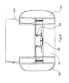
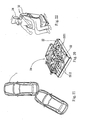
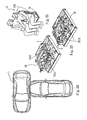
- a car in accordance with the preferred embodiment of the present invention comprises a car body 1 having a periphery provided with a plurality of lever-type hydraulic cylinders 11, and a safety seat system mounted in the car body 1 and connected to each of the cylinders 11.
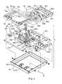
- the safety seat system in accordance with the preferred embodiment of the present invention comprises a displacement tipping device 2 including a first frame unit 21, a second frame unit 22, a third frame unit 23, a fourth frame unit 24, and a fifth frame unit 25.
- the first frame unit 21 includes a rectangular hollow base frame 211, a base rod 2111 mounted on a front end of the base frame 211, two pivot rods 212 each mounted on the base frame 211, and two support rods 213 each mounted between the pivot rods 212 and each provided with two slide seats 2130.
- the second frame unit 22 includes two passage rods 224 each mounted between the support rods 213 of the first frame unit 21 and each having two ends each mounted on the respective slide seat 2130 of the respective support rod 213, two support brackets 221 having different shapes and each mounted on the respective passage rod 224, a first connecting rod 222 mounted between first ends of the support brackets 221, a second connecting rod 223 mounted between mediate portions of the support brackets 221, and a linkage 225 mounted between the support brackets 221.
- the linkage 225 of the second frame unit 22 includes two guide plates 226 each mounted on the first end of the respective support bracket 221 and each formed with a guide slot 2260, two recessed guide tracks 2211 each mounted on the respective support bracket 221 and each located adjacent to the second connecting rod 223, an operation rod 227 movably mounted between the guide tracks 2211 and limited by the second connecting rod 223, two operation plates 2271 each having a first end mounted on the operation rod 227, a transverse rod 2251 mounted between second ends of the operation plates 2271, two connecting plates 2252 each having a first end mounted on one of two ends of the transverse rod 2251, two connecting rods 2255 each having a first end mounted on a second end of the respective connecting plate 2252, two ears 2254 each movably mounted on the respective guide plate 226 and each having a first side mounted on a second end of the respective connecting rod 2255 and a second side provided with a driven rod 2253 movable in the guide slot 2260 of the respective guide plate 226.
- the third frame unit 23 includes a pivot frame 231 having a first linking rod 2310 mounted between second ends of the support brackets 221, a second linking rod 2311 mounted between the ears 2254 of the second frame unit 22, a pivot rod 2312 mounted between first ends of the first linking rod 2310 and the second linking rod 2311, and a connecting plate 2313 mounted between second ends of the first linking rod 2310 and the second linking rod 2311, a slide 232 slidably mounted between the first linking rod 2310 and the second linking rod 2311 of the pivot frame 231, and a guide rod 233 mounted between the pivot rod 2312 and the connecting plate 2313 of the pivot frame 231 and extended through the slide 232.
- the fourth frame unit 24 includes a first bar 241 provided with two pairs of pivot plates 2411 connected with the first linking rod 2310 and the second linking rod 2311, a second bar 242 pivotally mounted on the slide 232 of the third frame unit 23, and two connecting plates 243 each mounted between the ,first bar 241 and the second bar 242.
- the fifth frame unit 25 includes a fixing frame 251 mounted on the first bar 241 and the second bar 242 of the fourth frame unit 24.
- the displacement tipping device 2 further includes two first cylinders 2112 each having a first end mounted on the base rod 2111 of the first frame unit 21 and a second end mounted on one of the support brackets 221 of the second frame unit 22, two second cylinders 2242 each having a first end mounted on the respective slide seat 2130 of the first frame unit 21 and a second end mounted on the second connecting rod 223 of the second frame unit 22, a third cylinder 2221 having a first end mounted on the first connecting rod 222 of the second frame unit 22 and a second end mounted on the transverse rod 2251 of the second frame unit 22, two fourth cylinders 2321 each having a first end mounted on the pivot rod 2312 of the third frame unit 23 and a second end mounted on the slide 232 of the third frame unit 23, and a fifth cylinder 2331 having a first end mounted on the operation rod 227 of the second frame unit 22 and a second end mounted on the guide rod 233 of the third frame unit 23.
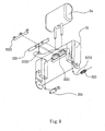
- the safety seat system further comprises a seat assembly 3 mounted on a top of the displacement tipping device 2.
- the seat assembly 3 includes a seat 3 1, a lower backrest 33 mounted on the seat 31, an upper backrest 32 mounted on the lower backrest 33, a headrest 34 mounted on the upper backrest 32, a shaft 35 mounted on a connection of the upper backrest 32 and the lower backrest 33, two drive plates 351 mounted on two ends of the shaft 35 respectively, two stubs 352 each mounted on the respective drive plate 351, two forward inclining cylinder units 36 each connected with the respective stub 352, and two columns 321 each mounted in the upper backrest 32 and each connected with the respective cylinder units 36.
- the cylinder units 36 are expanded outwardly, the upper backrest 32 and the headrest 34 are lifted in a forward inclining manner relative to the lower backrest 33.
- the seat assembly 3 further includes two protective wings 331 mounted on two sides of the lower backrest 33 respectively, two pivot shafts 333 mounted in the lower backrest 33, a lower backrest cylinder 332 mounted in the lower backrest 33, and two connecting wires 3321 each mounted around the respective pivot shaft 333 and each having a first end connected to the lower backrest cylinder 332 and a second end connected to the respective protective wing 331.
- the protective wings 331 are moved toward each other by the connecting wires 3321.
- the seat assembly 3 further includes a fixing bar 322 rotatably mounted in the upper backrest 32 and secured to the headrest 34 to rotate the headrest 34, two covers 3221 mounted in the upper backrest 32 to 20 cover the fixing bar 322, a drive disk 3222 secured to the fixing bar 322 to rotate the fixing bar 322, two wires 3223 each having a first end connected to the drive disk 3222, a headrest cylinder 324 mounted in the upper backrest 32 and connected to a second end of one of the wires 3223, and an elastic member 323 mounted in the upper backrest 32 and connected to a second end of the other one of the wires 3223.
- the drive disk 3222 is rotated by one of the wires 3223 to rotate the fixing bar 322 so as to rotate the headrest 34.
- the first cylinders 2112, the second cylinders 2242, the third cylinder 2221, the fourth cylinders 2321, the fifth cylinder 2331, the cylinder units 36 and the lower backrest cylinder 332 are double directional hydraulic cylinders.
- the first cylinders 2112 is connected to the cylinders 11 at the front portion, two sides of the front portion, the rear portion and two sides of the rear portion of the car body 1
- the second cylinders 2242 is connected to the cylinders 11 at the left side and the right side of the car body 1
- the third cylinder 2221 is connected to the cylinders 11 at two sides of the front portion, two sides of the rear portion, the left side and the right side of the car body 1
- the fourth cylinders 2321 is connected to the cylinders 11 at the front portion and two sides of the front portion of the car body 1
- the fifth cylinder 2331 is connected to the cylinders 11 at the left side and the right side of the car body 1
- the lower backrest cylinder 332 is connected to the cylinders 11 at the front portion, two sides of the front portion, the left side and the right side of the car body 1
- the cylinder units 36 is connected to the rear portion and two sides of the rear portion of the car body 1
- the headrest cylinder 324 is
- the displacement tipping device 2 and the seat assembly 3 are operated to provide a reaction to eliminate or reduce the external hitting force.
- each of the first cylinders 2112 is mounted between the base rod 2111 of the first frame unit 21 and one of the support brackets 221 of the second frame unit 22, so that when the first cylinders 2112 are operated and expanded by the hydraulic oil, the second frame unit 22 is pushed by the first cylinders 2112 to move rearward so as to move the seat assembly 3 rearward, such that the driver's body is moved rearward quickly to prevent the driver's body from being hit.
- each of the fourth cylinders 2321 is mounted between the pivot rod 2312 of the third frame unit 23 and the slide 232 of the third frame unit 23, so that when the fourth cylinders 2321 are operated and expanded by the hydraulic oil, the slide 232 of the thirdframe unit 23 is pushed by the fourth cylinders 2321 to move toward the connecting plate 2313 of the third frame unit 23 to push the fourth frame unit 24 which pushes the pivot plates 2411 to pivot upward relative to the third frame unit 23 to raise the fourth frame unit 24 so as to raise the seat assembly 3 in an inclined manner, such that the driver's legs are lifted to a determined angle to protect the driver's legs.
- each of the first cylinders 2112 is mounted between the base rod 2111 of the first frame unit 21 and one of the support brackets 221 of the second frame unit 22, so that when the first cylinders. 2112 are operated and expanded by the hydraulic oil, the second frame unit 22 is pushed by the first cylinders 2112 to move rearward so as to move the seat assembly 3 rearward, such that the driver's body is moved rearward quickly,to prevent the driver's body from being hit.
- the third cylinder 2221 is mounted between the first connecting rod 222 of the second frame unit 22 and the transverse rod 2251 of the second frame unit 22, so that when the third cylinder 2221 is operated and expanded by the hydraulic oil, the linkage 225 of the second frame unit 22 is pushed by the third cylinder 2221 to move toward the second connecting rod 223.
- each of the ears 2254 of the second frame unit 22 is movable downward on the respective guide plate 226 in an inclined manner to move the second linking rod 2311 of the third frame unit 23 downward relative to the first linking rod 2310 of the third frame unit 23, so that the third frame unit 23 is inclined sideward toward the central portion of the car body 1, and the seat assembly 3 is inclined sideward toward the central portion of the car body 1 to protect the driver's body.
- each of the fourth cylinders 2321 is mounted between the pivot rod 2312 of the third frame unit 23 and the slide 232 of the third frame unit 23, so that when the fourth cylinders 2321 are operated and expanded by the hydraulic oil, the slide 232 of the third frame unit 23 is pushed by the fourth cylinders 2321 to move toward the connecting plate 2313 of the third frame unit 23 to push the fourth frame unit 24 which pushes the pivot plates 2411 to pivot upward relative to the third frame unit 23 to raise the fourth frame unit 24 so as to raise the seat assembly 3 in an inclined manner, such that the driver's legs are lifted to a determined angle to protect the driver's legs.
- each of the first cylinders 2112 is mounted between the base rod 2111 of the first frame unit 21 and one of the support brackets 221 of the second frame unit 22, so that when the first cylinders 2112 are operated and expanded by the hydraulic oil, the second frame unit 22 is pushed by the first cylinders 2112 to move rearward so as to move the seat assembly 3 rearward, such that the driver's body is moved rearward quickly to prevent the driver's body from being hit.
- each of the first cylinders 2112 is mounted between the base rod 2111 of the first frame unit 21 and one of the support brackets 221 of the second frame unit 22, so that when the first cylinders 2112 are operated and expanded by the hydraulic oil, the second frame unit 22 is pushed by the first cylinders 2112 to move rearward so as to move the seat assembly 3 rearward, such that the driver's body is moved rearward quickly to prevent the driver's body from being hit.
- the third cylinder 2221 is mounted between the first connecting rod 222 of the second frame unit 22 and the transverse rod 2251 of the second frame unit 22, so that when the third cylinder 2221 is operated and expanded by the hydraulic oil, the linkage 225 of the second frame unit 22 is pushed by the third cylinder 2221 to move toward the second connecting rod 223.
- each of the ears 2254 of the second frame unit 22 is movable downward on the respective guide plate 226 in an inclined manner to move the second linking rod 2311 of the third frame unit 23 downward relative to the first linking rod 2310 of the third frame unit 23, so that the third frame unit 23 is inclined sideward toward the central portion of the car body 1, and the seat assembly 3 is inclined sideward toward the central portion of the car body 1 to protect the driver's body.
- the drive disk 3222 is rotated by one of the wires 3223 to rotate the fixing bar 322 to rotate the headrest 34 so as to protect the driver's head.
- each of the second cylinders 2242 is mounted between the respective slide seat 2130 of the first frame unit 21 and the second connecting rod 223 of the second frame unit 22, so that when the second cylinders 2242 are operated and expanded by the hydraulic oil, the second frame unit 22 is pushed by the second cylinders 2242 to move toward the central portion of the car body 1 quickly to prevent the driver's body from being hit.
- the third cylinder 2221 is mounted between the first connecting rod 222 of the second frame unit 22 and the transverse rod 2251 of the second frame unit 22, so that when the third cylinder 2221 is operated and expanded by the hydraulic oil, the linkage 225 of the second frame unit 22 is pushed by the third cylinder 2221 to move toward the second connecting rod 223.
- each of the ears 2254 of the second frame unit 22 is movable downward on the respective guide plate 226 in an inclined manner to move the second linking rod 2311 of the third frame unit 23 downward relative to the first linking rod 2310 of the third frame unit 23, so that the third frame unit 23 is inclined sideward toward the central portion of the car body 1, and the seat assembly 3 is inclined sideward toward the central portion of the car body 1 to protect the driver's body.
- the fifth cylinder 2331 is mounted between the operation rod 227 of the second frame unit 22 and the guide rod 233 of the third frame unit 23, so that when the fifth cylinder 2331 is operated and expanded by the hydraulic oil, the second linking rod 2311 of the third frame unit 23 is pushed by the fifth cylinder 2331 to drive the ears 2254 of the second frame unit 22 to move upward on the guide plates 226.
- the seat assembly 3 produces a smaller inclined angle along the hitting direction, so that the driver's body produces a reaction to eliminate or reduce the sideward hitting force to protect the driver's body.
- the seat assembly 3 is inclined sideward toward the central portion of the car body 5 to protect the driver's body.
- each of the cylinders 11 of the car body 1 is provided with a lever-type drive plate 111 having a distal end provided with a fulcrum 112.
- the drive plates 111 of the cylinders 11 are arranged in an overlapping manner or in a staggered manner.
- the front drive plate 111 pushes the rear drive plate 111 to push the two cylinders 11 together so as to operate the displacement tipping device 2 quickly.
- the car body 1 has a periphery provided with a plurality of lever-type hydraulic cylinders 11, and the safety seat system comprises a displacement tipping device 2 and a seat assembly 3 connected to the cylinders 11, so that when the car body 1 is subjected to a hit or collision in any direction, the displacement tipping device 2 produces a relative reaction to eliminate or reduce the hitting force and also drives the seat assembly 3 to move toward the central portion of the car body 1 quickly to prevent the driver's body from being hit directly so as to protect the driver's body.
- the protective wings 331 are moved toward each other to clamp and protect the driver's waist.
- the upper backrest 32 and the headrest 34 are lifted in a forward inclining manner relative to the lower backrest 33 to protect the driver's head and neck.
- the drive disk 3222 is rotated by one of the wires 3223 to rotate the fixing bar 322 to rotate the headrest 34 so as to protect the driver's head.
Landscapes
- Engineering & Computer Science (AREA)
- Aviation & Aerospace Engineering (AREA)
- Transportation (AREA)
- Mechanical Engineering (AREA)
- Seats For Vehicles (AREA)
- Forklifts And Lifting Vehicles (AREA)
Claims (10)
- Ein Auto mit:einer Fahrzeugkarosserie, deren Außenseite mit einer Vielzahl von Zylindern (11) ausgestattet ist, wobei eine Sicherheitssitzvorrichtung in der Fahrzeugkarosserie (1) montiert und mit jedem der Zylinder verbunden ist;wobei die Sicherheitssitzvorrichtung ein Ablöseverkippungsgerät (2) enthält mit:einer ersten Rahmeneinheit (21) mit einem hohlen Basisrahmen (211), einem Basisstab (2111), der am vorderen Ende des Basisrahmens (211) montiert ist, zwei Achsstangen (212), wobei jede am Basisrahmen (211) montiert ist und zwei Stützstangen (213), wobei jede zwischen den Achsstangen (212) montiert ist und wobei jede mit zwei Schiebesitzen (2130) ausgestattet ist;einer zweiten Rahmeneinheit (22) mit zwei Durchgangsstangen (224), wobei jede zwischen den Stützstangen (213) der ersten Rahmeneinheit (21) montiert ist und jede mit zwei Enden, von denen jedes am entsprechenden Schiebesitz (2130) der jeweiligen Stützstange (213) montiert ist, zwei Befestigungsbügeln (221), die jeweils an der entsprechenden Stützstange (224) montiert sind, einer ersten Verbindungsstange (222), die zwischen den ersten Enden der Befestigungsbügel (221) montiert ist, einer zweiten Verbindungsstange (223), die zwischen den Mittelteilen der Befestigungsbügel (221) montiert ist, und einem Gestänge (225), das zwischen den Befestigungsbügeln (221) montiert ist;einer dritten Rahmeneinheit (23) mit einem Achsrahmen (231), der eine erste Verbindungsstange (2310), die zwischen den zweiten Enden der Befestigungsbügel (221) montiert ist, eine zweite Verbindungsstange (2311), die auf dem Gestänge der zweiten Rahmeneinheit (22) montiert ist, eine Achsstange (2312), die zwischen den ersten Enden der ersten Verbindungsstange (2310) und der zweiten Verbindungsstange (2311) montiert ist, und eine Verbindungsplatte (2313), die zwischen den zweiten Enden der ersten Verbindungsstange (2310) und der zweiten Verbindungsstange (2311) montiert ist, enthält, einem Gleitstück (232), das gleitbar zwischen der ersten Verbindungsstange (2310) und der zweiten Verbindungsstange (2311) des Achsrahmens (231) montiert ist, und einer Führungsstange (233), die zwischen der Achsstange (2312) und der Verbindungsplatte (2313) des Achsrahmens (231) montiert ist und durch das Gleitstück (232) herausragt;einer vierten Rahmeneinheit (24) mit einem ersten Balken (241), der mit zwei paar Achsplatten (2411) ausgestattet ist, die mit der ersten Verbindungsstange (2310) und der zweiten Verbindungsstange (2311) verbunden sind, einem zweiten Balken (242), der drehbar an dem Gleitstück (232) der dritten Rahmeneinheit (23) montiert ist und zwei Verbindungsplatten (243), wobei jede zwischen dem ersten Balken (241) und dem zweiten Balken (242) montiert ist;einer fünften Rahmeneinheit (25) mit einem Befestigungsrahmen (251), der an dem ersten Balken (241) und dem zweiten Balken (242) der vierten Rahmeneinheit (24) montiert ist;zwei ersten Zylindern (2112), deren erstes Ende an dem Basisstab (2111) der ersten Rahmeneinheit (21) und deren zweites Ende an einem der Befestigungsbügel (221) der zweiten Rahmeneinheit (22) montiert ist;zwei zweiten Zylindern (2242), deren erstes Ende am entsprechenden Schiebesitz (2130) der ersten Rahmeneinheit (21) und deren zweites Ende an der zweiten Verbindungsstange (223) der zweiten Rahmeneinheit (22) montiert ist;einem dritten Zylinder (2221), dessen erstes Ende an der ersten Verbindungsstange (222) der zweiten Rahmeneinheit (22) und dessen zweites Ende am Gestänge der zweiten Rahmeneinheit (22) montiert ist;zwei vierte Zylinder (2321) deren erstes Ende an der Achsstange (2312) der dritten Rahmeneinheit (23) und deren zweites Ende auf dem Gleitstück (232) der dritten Rahmeneinheit (23) montiert ist;einem fünften Zylinder (2331), dessen erstes Ende am Gestänge der zweiten Rahmeneinheit (22) und dessen zweites Ende an der Führungsstange (233) der dritten Rahmeneinheit (23) montiert ist.
- Auto gemäß Anspruch 1, dadurch gekennzeichnet, dass das Gestänge der zweiten Rahmeneinheit (22) zwei Führungsplatten (226), von denen jede am ersten Ende des entsprechenden Befestigungsbügels montiert ist, wobei jede mit einem Führungsschlitz (2260) ausgestattet ist, zwei ausgesparte Führungsbahnen (2211), von denen jede auf dem entsprechenden Befestigungsbügel (2211) montiert ist und von denen jede angrenzend an die zweite Verbindungsstange (223) angeordnet ist, eine Betriebsstange (227), die beweglich zwischen den Führungsbahnen (2211) montiert ist und durch die zweite Verbindungsstange (223) begrenzt wird, zwei Betriebsplatten (2271), von denen jede am ersten Ende an der Betriebsstange (227) montiert ist, eine Querstange (2251), die zwischen den zweiten Enden der Betriebsplatten (2271) montiert ist, zwei Verbindungsplatten (2252), von denen jede am ersten Ende an einem der beiden Enden der Querstange (2251) montiert ist, zwei Verbindungsstangen (2255), von denen jede am ersten Ende an einem zweiten Ende der entsprechenden Verbindungsplatte (2252) montiert ist, zwei Ösen (2254), von denen jede beweglich an der entsprechenden Führungsplatte (226) montiert ist, wobei jede an ihrer ersten Seite an einem zweiten Ende der entsprechenden Verbindungsstange (2255) montiert ist und ihre zweite Seite mit einer im Führungsschlitz (2260) der entsprechenden Führungsplatte (226) beweglichen Antriebsstange (2253) ausgestattet ist, enthält.
- Auto gemäß Anspruch 2, dadurch gekennzeichnet, dass das zweite Ende des dritten Zylinders (23) auf der Querstange der zweiten Rahmeneinheit (22), das erste Ende des fünften Zylinders (25) auf der Betriebsstange (227) der zweiten Rahmeneinheit (22), und die zweite Verbindungsstange (2311) der dritten Rahmeneinheit (23) zwischen den Ösen der zweiten Rahmeneinheit (22) montiert ist.
- Auto gemäß Anspruch 1, dadurch gekennzeichnet, dass die Sicherheitssitzvorrichtung weiter eine Sitzanordnung (3) enthält, die oben auf dem Ablöseverkippungsgerät (2) montiert ist, und einen Sitz (31), eine untere Rückenlehne (33), die am Sitz (31) montiert ist, eine obere Rückenlehne (32), die auf der unteren Rückenlehne (33) montiert ist, und eine Kopfstütze (34), die auf der oberen Rückenlehne (33) montiert ist, umfasst.
- Auto gemäß Anspruch 4, dadurch gekennzeichnet, dass die Sitzanordnung (3) weiter eine Achse (35), die auf einer Verbindung der oberen Rückenlehne (32) und der unteren Rückenlehne (32) montiert ist, zwei Mitnehmerscheiben (351), die jeweils an beiden Enden der Achse (35) montiert sind, zwei Halterungen (352), die jeweils an der entsprechenden Mitnehmerscheibe (351) montiert sind, zwei vorwärts geneigte Zylindereinheiten (36), die jeweils mit der entsprechenden Halterung (352) verbunden sind, und zwei Stützen (321), die jeweils in der oberen Rückenlehne (32) montiert sind und jede mit den entsprechenden Zylindereinheiten (36) verbunden ist, so dass, wenn die Zylindereinheiten (36) nach außen ausgedehnt werden, die obere Rückenlehne (32) and die Kopfstütze (34) in einer vorwärts geneigten Weise relativ zur unteren Rückenlehne angehoben werden, enthält.
- Auto gemäß Anspruch 4, dadurch gekennzeichnet, dass die Sitzanordnung weiter zwei Schutzflügel (331), die an jeweils zwei Seiten der unteren Rückenlehne (33) montiert sind, zwei Achsen (333), die in der unteren Rückenlehne (33) montiert sind, ein unterer Rückenlehnenzylinder (332), der in der unteren Rückenlehne (33) montiert ist, und zwei Verbindungsdrähte (3321) enthält, die jeweils rund um die entsprechenden Achse (333) angebracht sind, wobei jeder mit dem ersten Ende mit dem unteren Rückenlehnenzylinder (332) und mit einem zweiten Ende mit dem entsprechenden Schutzflügel (331) verbunden ist, so dass, wenn der untere Rückenlehnenzylinder (332) nach außen ausgedehnt wird, die Schutzflügel (331) durch die Verbindungsdrähte (3321) zueinander hin bewegt werden.
- Auto gemäß Anspruch 4, dadurch gekennzeichnet, dass die Sitzanordnung (3) weiter einen Befestigungsbalken (322), der drehbar in der oberen Rückenlehne (32) montiert ist und an der Kopfstütze (34) befestigt ist, um die Kopfstütze (34) zu drehen, zwei Abdeckungen (3221), die in der oberen Rückenlehne (32) montiert sind, um den Befestigungsbalken (322) abzudecken, eine Antriebsscheibe (3222), die auf dem Befestigungsbalken (322) befestigt ist, um den Befestigungsbalken (322) zu drehen, zwei Drähte (3223), die jeweils mit einem ersten Ende mit der Antriebsscheibe (3222) verbunden sind, ein Kopfstützenzylinder (324), der in der oberen Rückenlehne (32) montiert und mit einem zweiten Ende eines der Drähte (3223) verbunden ist, und ein elastisches Teil (323) enthält, das in der oberen Rückenlehne (32) montiert ist und mit einem zweiten Ende des anderen Drahtes (3223) verbunden ist, so dass, wenn der Kopfstützenzylinder (324) betätigt und ausgedehnt wird, die Antriebsscheibe (3222) durch einen der Drähte gedreht wird, um den Befestigungsbalken (322) zu drehen, um so die Kopfstütze (34) zu drehen.
- Auto gemäß Anspruch 5 oder 6, dadurch gekennzeichnet, dass die ersten Zylinder (2112), die zweiten Zylinder (2242), die dritten Zylinder (2221), die vierten Zylinder (2321), die fünften Zylinder (2331), die Zylindereinheiten (36) und der untere Rückenlehnenzylinder (332) doppeltwirkende Hydraulikzylinder sind.
- Auto gemäß Anspruch 1, dadurch gekennzeichnet, dass jeder der Zylinder der Fahrzeugkarosserie mit einer Hebelplatte (111) ausgestattet ist, deren entferntes Ende mit einem Hebelpunkt (112) ausgestattet ist.
- Auto gemäß Anspruch 5, 6 oder 7, dadurch gekennzeichnet, dass die ersten Zylinder (2112) mit den Zylindern (11) am vorderen Teil, zwei Seiten des vorderen Teils, dem hinteren Teil und zwei Seiten des hinteren Teils der Fahrzeugkarosserie (1) verbunden sind, dass die zweiten Zylinder (2242) mit den Zylindern (11) an der linken Seite und an der rechten Seite der Fahrzeugkarosserie (1) verbunden sind, dass der dritte Zylinder (2221) mit den Zylindern (11) an zwei Seiten des vorderen Teils, zwei Seiten des hinteren Teils, der linken Seite und der rechten Seite der Fahrzeugkarosserie (1) verbunden ist, dass die vierten Zylinder (2321) mit den Zylindern (11) am vorderen Teil und zwei Seiten des vorderen Teils der Fahrzeugkarosserie (1) verbunden ist, dass der fünfte Zylinder (2331) mit den Zylindern (11) an der linken Seite und der rechten Seite der Fahrzeugkarosserie (1) verbunden ist, dass der untere Rückenlehnenzylinder (332) mit den Zylindern (11) am vorderen Teil, zwei Seiten des vorderen Teils, der linken Seite und der rechten Seite der Fahrzeugkarosserie (1) verbunden ist, dass die Zylindereinheiten (36) mit dem hinteren Teil und zwei Seiten des hinteren Teils der Fahrzeugkarosserie (1) verbunden ist, und der Kopfstützenzylinder (324) mit zwei Seiten des hinteren Teils der Fahrzeugkarosserie (1) verbunden ist.
Priority Applications (3)
| Application Number | Priority Date | Filing Date | Title |
|---|---|---|---|
| DE602006017516T DE602006017516D1 (de) | 2006-05-20 | 2006-05-20 | Sicherheitssitzvorrichtung für Wagen |
| AT06010449T ATE484415T1 (de) | 2006-05-20 | 2006-05-20 | Sicherheitssitzvorrichtung für wagen |
| EP06010449A EP1857320B1 (de) | 2006-05-20 | 2006-05-20 | Sicherheitssitzvorrichtung für Wagen |
Applications Claiming Priority (1)
| Application Number | Priority Date | Filing Date | Title |
|---|---|---|---|
| EP06010449A EP1857320B1 (de) | 2006-05-20 | 2006-05-20 | Sicherheitssitzvorrichtung für Wagen |
Publications (2)
| Publication Number | Publication Date |
|---|---|
| EP1857320A1 EP1857320A1 (de) | 2007-11-21 |
| EP1857320B1 true EP1857320B1 (de) | 2010-10-13 |
Family
ID=37806051
Family Applications (1)
| Application Number | Title | Priority Date | Filing Date |
|---|---|---|---|
| EP06010449A Expired - Lifetime EP1857320B1 (de) | 2006-05-20 | 2006-05-20 | Sicherheitssitzvorrichtung für Wagen |
Country Status (3)
| Country | Link |
|---|---|
| EP (1) | EP1857320B1 (de) |
| AT (1) | ATE484415T1 (de) |
| DE (1) | DE602006017516D1 (de) |
Families Citing this family (6)
| Publication number | Priority date | Publication date | Assignee | Title |
|---|---|---|---|---|
| WO2012005281A1 (ja) | 2010-07-09 | 2012-01-12 | テイ・エス テック株式会社 | 車両用シート |
| EP2591949A4 (de) | 2010-07-09 | 2016-04-27 | Ts Tech Co Ltd | Fahrzeugsitz |
| JP5805638B2 (ja) | 2010-07-09 | 2015-11-04 | テイ・エス テック株式会社 | 車両用シート |
| CN102529774B (zh) * | 2010-12-29 | 2016-02-17 | 株式会社塔捷斯 | 座椅靠背的框架结构体 |
| EP2476584B1 (de) * | 2011-01-14 | 2016-11-16 | Tachi-S Co., Ltd. | Sitzlehnenrahmen |
| KR102590092B1 (ko) * | 2023-04-27 | 2023-10-19 | (주)케이엠앤아이 | 시트백 충격흡수장치 및 이를 포함하는 시트 |
Family Cites Families (5)
| Publication number | Priority date | Publication date | Assignee | Title |
|---|---|---|---|---|
| FR1207101A (fr) * | 1961-10-25 | 1960-02-15 | Pare-chocs amortisseur | |
| US3858930A (en) * | 1972-07-11 | 1975-01-07 | Donald A Calandra | Safety vehicle seat system and trigger means for the same |
| DE19530219A1 (de) * | 1995-08-17 | 1996-04-25 | Giok Djien Dr Ing Go | Ersatzsysteme für Seitenairbag bei PKW und LKW in realem seitlichem Unfallgeschehen |
| JP3904384B2 (ja) * | 2000-10-31 | 2007-04-11 | 本田技研工業株式会社 | 乗員保護装置 |
| EP1325836B1 (de) * | 2001-04-02 | 2007-07-18 | Arjuna Indraeswaren Dr. Rajasingham | Leichtgängiger Ausstosser mit skelettartigem unfallsicheren Balken |
-
2006
- 2006-05-20 DE DE602006017516T patent/DE602006017516D1/de not_active Expired - Lifetime
- 2006-05-20 EP EP06010449A patent/EP1857320B1/de not_active Expired - Lifetime
- 2006-05-20 AT AT06010449T patent/ATE484415T1/de not_active IP Right Cessation
Also Published As
| Publication number | Publication date |
|---|---|
| EP1857320A1 (de) | 2007-11-21 |
| DE602006017516D1 (de) | 2010-11-25 |
| ATE484415T1 (de) | 2010-10-15 |
Similar Documents
| Publication | Publication Date | Title |
|---|---|---|
| CN107009928B (zh) | 自动头枕 | |
| EP1646528B1 (de) | Verstellbare seitenpolster | |
| US20020113483A1 (en) | Active headrest for a vehicle seat | |
| EP1744931B1 (de) | Integriertes lordosen- und kopfstützensystem | |
| CN106143241B (zh) | 头枕装置 | |
| CN101272930B (zh) | 车辆座椅的头枕用连结机构 | |
| EP1147939A2 (de) | Motorgetriebene Sitzfussstütze | |
| CN112744136B (zh) | 车辆座椅装置 | |
| CN102205808A (zh) | 一种车用座椅靠背骨架 | |
| EP1857320A1 (de) | Sicherheitssitzvorrichtung für Wagen | |
| JP5448622B2 (ja) | 車両用シート | |
| CN101296819A (zh) | 活动头枕 | |
| EP1726476A2 (de) | Fahrzeugsitz und Verfahren zur Abstützung eines Fahrers/Beifahrers unter Verwendung eines derartigen Fahrzeugsitzes | |
| US9387777B2 (en) | Seat underframe for motor vehicle seats | |
| US6840560B2 (en) | Vehicular seat assembly having a movable headrest and a vehicle which incorporates the vehicular seat assembly | |
| CN102529763A (zh) | 车辆用座椅 | |
| EP1636065B1 (de) | Fahrzeugsitz | |
| CN101920670B (zh) | 一种用于车辆乘员安全的保护装置 | |
| US7887116B2 (en) | Vehicle occupant protection system by pivoting seats upward in case of a crash | |
| JP4624299B2 (ja) | シートを素早く移動且つ傾斜する装置 | |
| EP1325836A2 (de) | Leichtgängiger Ausstosser mit skelettartigem unfallsicheren Balken | |
| JP5229524B2 (ja) | 車両のシート構造 | |
| JP4967303B2 (ja) | 車両用シートの支持構造 | |
| JP5156191B2 (ja) | アクティブヘッドレストシステムを備えた車両シート | |
| CN105980202A (zh) | 汽车头部约束保护系统 |
Legal Events
| Date | Code | Title | Description |
|---|---|---|---|
| PUAI | Public reference made under article 153(3) epc to a published international application that has entered the european phase |
Free format text: ORIGINAL CODE: 0009012 |
|
| 17P | Request for examination filed |
Effective date: 20060822 |
|
| AK | Designated contracting states |
Kind code of ref document: A1 Designated state(s): AT BE BG CH CY CZ DE DK EE ES FI FR GB GR HU IE IS IT LI LT LU LV MC NL PL PT RO SE SI SK TR |
|
| AX | Request for extension of the european patent |
Extension state: AL BA HR MK YU |
|
| AKX | Designation fees paid |
Designated state(s): AT BE BG CH CY CZ DE DK EE ES FI FR GB GR HU IE IS IT LI LT LU LV MC NL PL PT RO SE SI SK TR |
|
| GRAP | Despatch of communication of intention to grant a patent |
Free format text: ORIGINAL CODE: EPIDOSNIGR1 |
|
| GRAS | Grant fee paid |
Free format text: ORIGINAL CODE: EPIDOSNIGR3 |
|
| GRAA | (expected) grant |
Free format text: ORIGINAL CODE: 0009210 |
|
| AK | Designated contracting states |
Kind code of ref document: B1 Designated state(s): AT BE BG CH CY CZ DE DK EE ES FI FR GB GR HU IE IS IT LI LT LU LV MC NL PL PT RO SE SI SK TR |
|
| REG | Reference to a national code |
Ref country code: GB Ref legal event code: FG4D |
|
| REG | Reference to a national code |
Ref country code: CH Ref legal event code: EP |
|
| REG | Reference to a national code |
Ref country code: IE Ref legal event code: FG4D |
|
| REF | Corresponds to: |
Ref document number: 602006017516 Country of ref document: DE Date of ref document: 20101125 Kind code of ref document: P |
|
| REG | Reference to a national code |
Ref country code: NL Ref legal event code: VDEP Effective date: 20101013 |
|
| LTIE | Lt: invalidation of european patent or patent extension |
Effective date: 20101013 |
|
| PG25 | Lapsed in a contracting state [announced via postgrant information from national office to epo] |
Ref country code: LT Free format text: LAPSE BECAUSE OF FAILURE TO SUBMIT A TRANSLATION OF THE DESCRIPTION OR TO PAY THE FEE WITHIN THE PRESCRIBED TIME-LIMIT Effective date: 20101013 |
|
| PG25 | Lapsed in a contracting state [announced via postgrant information from national office to epo] |
Ref country code: SI Free format text: LAPSE BECAUSE OF FAILURE TO SUBMIT A TRANSLATION OF THE DESCRIPTION OR TO PAY THE FEE WITHIN THE PRESCRIBED TIME-LIMIT Effective date: 20101013 Ref country code: SE Free format text: LAPSE BECAUSE OF FAILURE TO SUBMIT A TRANSLATION OF THE DESCRIPTION OR TO PAY THE FEE WITHIN THE PRESCRIBED TIME-LIMIT Effective date: 20101013 Ref country code: PT Free format text: LAPSE BECAUSE OF FAILURE TO SUBMIT A TRANSLATION OF THE DESCRIPTION OR TO PAY THE FEE WITHIN THE PRESCRIBED TIME-LIMIT Effective date: 20110214 Ref country code: AT Free format text: LAPSE BECAUSE OF FAILURE TO SUBMIT A TRANSLATION OF THE DESCRIPTION OR TO PAY THE FEE WITHIN THE PRESCRIBED TIME-LIMIT Effective date: 20101013 Ref country code: BG Free format text: LAPSE BECAUSE OF FAILURE TO SUBMIT A TRANSLATION OF THE DESCRIPTION OR TO PAY THE FEE WITHIN THE PRESCRIBED TIME-LIMIT Effective date: 20110113 Ref country code: IS Free format text: LAPSE BECAUSE OF FAILURE TO SUBMIT A TRANSLATION OF THE DESCRIPTION OR TO PAY THE FEE WITHIN THE PRESCRIBED TIME-LIMIT Effective date: 20110213 Ref country code: FI Free format text: LAPSE BECAUSE OF FAILURE TO SUBMIT A TRANSLATION OF THE DESCRIPTION OR TO PAY THE FEE WITHIN THE PRESCRIBED TIME-LIMIT Effective date: 20101013 Ref country code: NL Free format text: LAPSE BECAUSE OF FAILURE TO SUBMIT A TRANSLATION OF THE DESCRIPTION OR TO PAY THE FEE WITHIN THE PRESCRIBED TIME-LIMIT Effective date: 20101013 Ref country code: LV Free format text: LAPSE BECAUSE OF FAILURE TO SUBMIT A TRANSLATION OF THE DESCRIPTION OR TO PAY THE FEE WITHIN THE PRESCRIBED TIME-LIMIT Effective date: 20101013 |
|
| PG25 | Lapsed in a contracting state [announced via postgrant information from national office to epo] |
Ref country code: GR Free format text: LAPSE BECAUSE OF FAILURE TO SUBMIT A TRANSLATION OF THE DESCRIPTION OR TO PAY THE FEE WITHIN THE PRESCRIBED TIME-LIMIT Effective date: 20110114 Ref country code: BE Free format text: LAPSE BECAUSE OF FAILURE TO SUBMIT A TRANSLATION OF THE DESCRIPTION OR TO PAY THE FEE WITHIN THE PRESCRIBED TIME-LIMIT Effective date: 20101013 |
|
| PG25 | Lapsed in a contracting state [announced via postgrant information from national office to epo] |
Ref country code: EE Free format text: LAPSE BECAUSE OF FAILURE TO SUBMIT A TRANSLATION OF THE DESCRIPTION OR TO PAY THE FEE WITHIN THE PRESCRIBED TIME-LIMIT Effective date: 20101013 Ref country code: ES Free format text: LAPSE BECAUSE OF FAILURE TO SUBMIT A TRANSLATION OF THE DESCRIPTION OR TO PAY THE FEE WITHIN THE PRESCRIBED TIME-LIMIT Effective date: 20110124 Ref country code: CZ Free format text: LAPSE BECAUSE OF FAILURE TO SUBMIT A TRANSLATION OF THE DESCRIPTION OR TO PAY THE FEE WITHIN THE PRESCRIBED TIME-LIMIT Effective date: 20101013 |
|
| PLBE | No opposition filed within time limit |
Free format text: ORIGINAL CODE: 0009261 |
|
| STAA | Information on the status of an ep patent application or granted ep patent |
Free format text: STATUS: NO OPPOSITION FILED WITHIN TIME LIMIT |
|
| PG25 | Lapsed in a contracting state [announced via postgrant information from national office to epo] |
Ref country code: PL Free format text: LAPSE BECAUSE OF FAILURE TO SUBMIT A TRANSLATION OF THE DESCRIPTION OR TO PAY THE FEE WITHIN THE PRESCRIBED TIME-LIMIT Effective date: 20101013 Ref country code: RO Free format text: LAPSE BECAUSE OF FAILURE TO SUBMIT A TRANSLATION OF THE DESCRIPTION OR TO PAY THE FEE WITHIN THE PRESCRIBED TIME-LIMIT Effective date: 20101013 Ref country code: SK Free format text: LAPSE BECAUSE OF FAILURE TO SUBMIT A TRANSLATION OF THE DESCRIPTION OR TO PAY THE FEE WITHIN THE PRESCRIBED TIME-LIMIT Effective date: 20101013 Ref country code: DK Free format text: LAPSE BECAUSE OF FAILURE TO SUBMIT A TRANSLATION OF THE DESCRIPTION OR TO PAY THE FEE WITHIN THE PRESCRIBED TIME-LIMIT Effective date: 20101013 |
|
| 26N | No opposition filed |
Effective date: 20110714 |
|
| REG | Reference to a national code |
Ref country code: DE Ref legal event code: R097 Ref document number: 602006017516 Country of ref document: DE Effective date: 20110714 |
|
| PG25 | Lapsed in a contracting state [announced via postgrant information from national office to epo] |
Ref country code: IT Free format text: LAPSE BECAUSE OF FAILURE TO SUBMIT A TRANSLATION OF THE DESCRIPTION OR TO PAY THE FEE WITHIN THE PRESCRIBED TIME-LIMIT Effective date: 20101013 Ref country code: MC Free format text: LAPSE BECAUSE OF NON-PAYMENT OF DUE FEES Effective date: 20110531 |
|
| REG | Reference to a national code |
Ref country code: CH Ref legal event code: PL |
|
| PG25 | Lapsed in a contracting state [announced via postgrant information from national office to epo] |
Ref country code: LI Free format text: LAPSE BECAUSE OF NON-PAYMENT OF DUE FEES Effective date: 20110531 Ref country code: CH Free format text: LAPSE BECAUSE OF NON-PAYMENT OF DUE FEES Effective date: 20110531 |
|
| REG | Reference to a national code |
Ref country code: IE Ref legal event code: MM4A |
|
| PG25 | Lapsed in a contracting state [announced via postgrant information from national office to epo] |
Ref country code: IE Free format text: LAPSE BECAUSE OF NON-PAYMENT OF DUE FEES Effective date: 20110520 |
|
| PGFP | Annual fee paid to national office [announced via postgrant information from national office to epo] |
Ref country code: DE Payment date: 20120529 Year of fee payment: 7 |
|
| PGFP | Annual fee paid to national office [announced via postgrant information from national office to epo] |
Ref country code: GB Payment date: 20120420 Year of fee payment: 7 Ref country code: FR Payment date: 20120607 Year of fee payment: 7 |
|
| PG25 | Lapsed in a contracting state [announced via postgrant information from national office to epo] |
Ref country code: LU Free format text: LAPSE BECAUSE OF NON-PAYMENT OF DUE FEES Effective date: 20110520 Ref country code: CY Free format text: LAPSE BECAUSE OF FAILURE TO SUBMIT A TRANSLATION OF THE DESCRIPTION OR TO PAY THE FEE WITHIN THE PRESCRIBED TIME-LIMIT Effective date: 20101013 |
|
| PG25 | Lapsed in a contracting state [announced via postgrant information from national office to epo] |
Ref country code: TR Free format text: LAPSE BECAUSE OF FAILURE TO SUBMIT A TRANSLATION OF THE DESCRIPTION OR TO PAY THE FEE WITHIN THE PRESCRIBED TIME-LIMIT Effective date: 20101013 |
|
| PG25 | Lapsed in a contracting state [announced via postgrant information from national office to epo] |
Ref country code: HU Free format text: LAPSE BECAUSE OF FAILURE TO SUBMIT A TRANSLATION OF THE DESCRIPTION OR TO PAY THE FEE WITHIN THE PRESCRIBED TIME-LIMIT Effective date: 20101013 |
|
| GBPC | Gb: european patent ceased through non-payment of renewal fee |
Effective date: 20130520 |
|
| PG25 | Lapsed in a contracting state [announced via postgrant information from national office to epo] |
Ref country code: DE Free format text: LAPSE BECAUSE OF NON-PAYMENT OF DUE FEES Effective date: 20131203 |
|
| REG | Reference to a national code |
Ref country code: DE Ref legal event code: R119 Ref document number: 602006017516 Country of ref document: DE Effective date: 20131203 |
|
| REG | Reference to a national code |
Ref country code: FR Ref legal event code: ST Effective date: 20140131 |
|
| PG25 | Lapsed in a contracting state [announced via postgrant information from national office to epo] |
Ref country code: GB Free format text: LAPSE BECAUSE OF NON-PAYMENT OF DUE FEES Effective date: 20130520 |
|
| PG25 | Lapsed in a contracting state [announced via postgrant information from national office to epo] |
Ref country code: FR Free format text: LAPSE BECAUSE OF NON-PAYMENT OF DUE FEES Effective date: 20130531 |