EP1857771B1 - Tastkopf und Konturmessgerät - Google Patents
Tastkopf und Konturmessgerät Download PDFInfo
- Publication number
- EP1857771B1 EP1857771B1 EP07009722A EP07009722A EP1857771B1 EP 1857771 B1 EP1857771 B1 EP 1857771B1 EP 07009722 A EP07009722 A EP 07009722A EP 07009722 A EP07009722 A EP 07009722A EP 1857771 B1 EP1857771 B1 EP 1857771B1
- Authority
- EP
- European Patent Office
- Prior art keywords
- probe
- module
- force sensor
- connecting portion
- sensor
- Prior art date
- Legal status (The legal status is an assumption and is not a legal conclusion. Google has not performed a legal analysis and makes no representation as to the accuracy of the status listed.)
- Ceased
Links
- 239000000523 sample Substances 0.000 title claims description 99
- 238000003780 insertion Methods 0.000 claims description 36
- 230000037431 insertion Effects 0.000 claims description 36
- 241001422033 Thestylus Species 0.000 claims description 21
- 238000001514 detection method Methods 0.000 claims description 19
- 239000000758 substrate Substances 0.000 description 33
- 238000012545 processing Methods 0.000 description 7
- 238000005259 measurement Methods 0.000 description 6
- 238000006243 chemical reaction Methods 0.000 description 2
- 239000004020 conductor Substances 0.000 description 2
- 238000006073 displacement reaction Methods 0.000 description 2
- 238000012986 modification Methods 0.000 description 2
- 230000004048 modification Effects 0.000 description 2
- 239000013585 weight reducing agent Substances 0.000 description 2
- 230000002238 attenuated effect Effects 0.000 description 1
- 238000010586 diagram Methods 0.000 description 1
- 229910003460 diamond Inorganic materials 0.000 description 1
- 239000010432 diamond Substances 0.000 description 1
- 239000002184 metal Substances 0.000 description 1
- 238000000034 method Methods 0.000 description 1
- 230000003287 optical effect Effects 0.000 description 1
- 239000010979 ruby Substances 0.000 description 1
- 229910001750 ruby Inorganic materials 0.000 description 1
- 238000009751 slip forming Methods 0.000 description 1
Images



Classifications
-
- G—PHYSICS
- G01—MEASURING; TESTING
- G01B—MEASURING LENGTH, THICKNESS OR SIMILAR LINEAR DIMENSIONS; MEASURING ANGLES; MEASURING AREAS; MEASURING IRREGULARITIES OF SURFACES OR CONTOURS
- G01B7/00—Measuring arrangements characterised by the use of electric or magnetic techniques
- G01B7/004—Measuring arrangements characterised by the use of electric or magnetic techniques for measuring coordinates of points
- G01B7/008—Measuring arrangements characterised by the use of electric or magnetic techniques for measuring coordinates of points using coordinate measuring machines
- G01B7/012—Contact-making feeler heads therefor
Definitions
- the present invention relates to a probe and a contour measuring instrument.
- the present invention relates to a contour measuring instrument and a probe used when a contour such as a profile and roughness of a surface of a workpiece is measured using a vibrating sensor.
- contour measuring instruments that measure a contour such as a profile and roughness of a surface of a workpiece by scanning the surface of the workpiece, the contour measuring instruments including a roughness measuring instrument, a profile measuring instrument, a roundness measuring instrument and a coordinate measuring instrument (see JP-A-2004-061 322 ).
- a vibrating force sensor (hereinafter, abbreviated as a force sensor) 1 as shown in Fig. 10 has been used as a sensor for detecting a surface of a workpiece based on a minute displacement of the contact portion contacting with the surface of the workpiece.
- the force sensor 1 shown in Fig. 10 includes a metal base 2, a stylus 3 integrally formed on the base 2, a vibrating element 4 that vibrates (in an axial direction) the stylus 3 and a detecting element 5 that detects a vibration state of the stylus 3 and outputs the vibration state as a detection signal.
- a contact pin (contact portion) 6 formed of a diamond chip, ruby and the like is fixedly bonded to a tip end of the stylus 3.
- the vibrating element 4 and the detecting element 5 are formed by a single piece of piezoelectric element, the piezoelectric element fixedly bonded on each of front and back surfaces of the base 2.
- a vibration signal Pi voltage signal
- the detecting element 5 obtains a detection signal Qo (voltage signal) having predetermined frequency and amplitude.
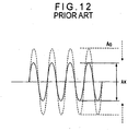
- Fig. 12 shows variation in the amplitude of the detection signal Qo caused by contact with a workpiece W.
- the stylus 3 In a state where the stylus 3 is not in contact with the workpiece W, when the vibration signal Pi having a certain amplitude at a resonance frequency of the stylus 3 is applied to the vibrating element 4, the stylus 3 resonates to provide the detection signal Qo having an amplitude Ao to the detecting element 5.
- the amplitude of the detection signal Qo attenuates from Ao to Ax.
- FIG. 13 A relationship between an attenuation rate k (Ax/Ao) and a measuring force is shown in Fig. 13 .
- the force sensor 1 when the stylus is broken or malfunctioned and unable to make a proper performance, the force sensor 1 needs to be replaced with a new one that can perform properly. In such a case, it is possible to replace a whole unit of the force sensor 1.
- crank pin By rotating the crank pin to bring the tip into contact with a lateral wall surface, the crank pin is locked.
- an insert seating section on which an insert is mounted is provided at a tip end of a holder, the insert seating portion provided with a dented pocket that extends through the insert seating section.
- a root of a pin of a pin member has a tapered surface, and a central hole of the insert is provided with a curved convex surface at a position engaging with the pin.
- the insert By fixedly fitting the pin member in the pocket by a fixing bolt and by pressing a hole wall of the central hole of the insert by the pin, the insert is locked on the insert seating portion.
- JP-A-10-100 006 In the arrangement of JP-A-10-100 006 , two components (i.e., the fixing bolt and the pin member) are required for locking the insert, which complicates the arrangement and degrades working efficiency of the locking.
- JP-A-2003 202 221 describes a vibrating probe which is detachably fixed to the probe head through three pins cooperating with holes. Coils arranged around the pins and the respective holes electromagnetically hold the probe on the probe head.
- An object of the present invention is to provide a probe and a contour measuring instrument that are capable of positioning a force sensor easily and highly reproducibly with a simple arrangement.
- a probe includes: a force sensor that detects a measuring force generated when the probe contacts with a workpiece and outputs the measuring force as a force detection signal; a position detector that detects a measuring position of the workpiece detected by the force sensor and outputs the measuring position as measuring position information; a relative moving section that relatively moves the force sensor and the workpiece; a probe body that is held by the relative moving section; a sensor module to which the force sensor is attached; and a fixing member that is inserted to the sensor module and the probe body, the fixing member detachably positioning and fixing the sensor module to the probe body, in which the probe body includes a substantially planar first positioning portion, a second positioning portion that is formed upright on the first positioning portion and an engaging hole that is provided to the first positioning portion, the engaging hole allowing the fixing member to be inserted thereinto and engaged therewith in a detachable manner, the sensor module includes a slidable-contact portion that slidably contacts with the first positioning portion, a pressing portion that is pressed against
- the fixing member includes the rod-like portion and the fixing projection.
- the probe body held by the relative moving section includes the first positioning portion, the second positioning portion formed upright on the first positioning portion and the engaging hole that is formed in the first positioning portion.
- the sensor module to which the force sensor is attached includes the slidable-contact portion, that slidably contacts with the first positioning portion, a pressing portion that is pressed against the second positioning portion and the insertion hole that communicates the slidable-contact portion side and the side opposite to the slidable-contact portion.
- the insertion hole has an inclined portion that inclines in such a manner that the diameter of the inclined portion of the insertion hole becomes gradually smaller toward the slidable-contact portion, the opening positioned on the side opposite to the slidable-contact portion.
- the insertion hole has a diameter larger than the thickness of the rod-like portion.
- positioning and fixing of the sensor module to the probe body can be performed as follows.
- the sensor module is positioned such that the slidable-contact portion faces the first positioning portion and the pressing portion faces the second positioning portion.
- the fixing member By inserting the fixing member into the insertion hole with the fixing projection slidably contacting with the inclined portion of the insertion hole, the rod-like portion is engaged with the engaging hole of the probe body, thereby positioning and fixing the sensor module to the probe body.
- the second positioning portion can be pressed against the pressing portion with the sensor module slidably contacting with the first positioning portion. Accordingly, the sensor module can be positioned easily and highly reproducibly in a planar direction of the first positioning portion.
- the rod-like portion can be engaged with the engaging hole with the inclined portion pressed by the fixing projection in a direction toward the first positioning portion.
- the sensor module can be positioned highly reproducibly in a direction substantially orthogonal to the planar direction of the first positioning portion.
- the arrangement can be simplified and work efficiency of the positioning can be enhanced.
- the force sensor can be positioned highly reproducibly with a simple arrangement.
- the force sensor preferably includes a stylus having a contact portion on a tip end thereof, a vibrating element that vibrates the stylus and a detecting element that detects a vibration state of the stylus and outputs the vibration state as a detection signal.
- the engaging hole is a female thread and the rod-like portion is a male screw.
- the sensor module can be positioned and fixed to the probe body, thereby realizing the positioning of the force sensor easily.
- the fixing projection is preferably continuously provided along a circumferential direction of the rod-like portion.
- the fixing projection can constantly abut on the inclined portion without necessity of carefully choosing the position of the fixing projection, thereby realizing the positioning of the force sensor even more easily.
- the rod-like portion can be screwed into the engaging hole with the fixing projection constantly abutting on the inclined portion, thereby realizing the positioning of the force sensor even more easily.
- the insertion hole is formed such that a distance between an end on the slidable-contact portion side of the inclined portion and the pressing portion is substantially equal to a distance between an end on the second positioning portion side of the engaging hole and the second engagement portion.
- the end on the slidable-contact portion side of the inclined portion and the end on the second positioning portion side of the engaging hole can be positioned collinearly with each other. Accordingly, the rod-like portion can be engaged with the engaging hole with the rod-portion substantially abutting on the end on the slid-contacting portion side of the inclined portion.
- the arrangement allows the fixing projection to abut on the inclined portion with the minimized projecting amount of the fixing projection from the lateral surface, which contributes to weight reduction of the fixing member and realizes measurement with higher accuracy.
- the probe body includes a body-connecting section that is provided on the first positioning portion and electrically coupled to a controlling section for controlling the relative moving section
- the sensor module includes a module-connecting portion that is provided at a position abuttable on the body-connecting portion in the slidable-contact portion side, the module-connecting portion electrically coupled to the force sensor and also electrically coupled to the body-connecting portion when the module-connecting portion abuts on the body-connecting portion.
- the controlling section and the force sensor can be connected in a signal-communicable manner.
- the body-connecting portion includes an advancement/retraction abutting portion that is advanceable/retractable in a direction intersecting with the first positioning portion, the module-connecting portion abutting on the advancement/retraction abutting portion.
- the body-connecting portion and the module-connecting portion can abut on each other with a substantially uniform force regardless of shapes of abutment portions of the connecting portions. Accordingly, the body-connecting portion and the module-connecting portion do not have to be precisely designed or produced, so that productivity can be enhanced.
- a portion adapted to abut on the module-connecting portion in the body-connecting portion is formed in a sphere.
- the body-connecting portion can point-contact with the module-connecting portion, which can reduce friction resistance in moving the sensor module toward the second positioning portion while slidably contacting with the first positioning portion.
- the positioning of the force sensor can be performed even more easily.
- the sensor module includes a storage section that is electrically coupled to the module-connecting portion and adapted to readably store specific property information about a property specific to the force sensor.
- the controlling section when the sensor module is positioned and fixed to the probe body, the controlling section reads and recognizes the specific property information stored in the storage section, so that the controlling section can control the relative moving section in accordance with the force sensor.
- a contour measuring instrument includes: the probe according to the above aspect; and a controlling section that drives the relative moving mechanism to bring the contact portion on a tip end of the probe into contact with the workpiece in such a manner that the detection signal from the force sensor is equal to a preset value and reads the measuring position information from the position detector to measure a contour of the workpiece from the measuring position information.
- the contour measuring instrument may further include the probe described above and a controlling section that reads the specific property information from the storage section, drives the relative moving mechanism under a control corresponding to the property specific to the force sensor to bring the contact portion of the probe into contact with the surface of the workpiece in such a manner that the detection signal from the force sensor is equal to a preset value and reads the measuring position information from the position detector to measure a contour of the workpiece from the measuring position information.
- the contour measuring instrument has advantages similar to those of the above-described probe.
- the contact-type scanning probe system 10 includes a probe 20, and a controller 30 as a controlling section that controls the probe 20.
- the probe 20 includes a casing 21 having a substantially rectangular parallelepiped shape, a module-fixing screw 100 (a fixing member), a probe body 200, a sensor module 300 that has a force sensor 1 and is detachably positioned and fixed to the probe body 200 by the module-fixing screw 100, an actuator 22 (relative moving section) that holds and advances/retracts the probe body 200 relative to a workpiece W, a scale 23 attached to the probe body 200, a scale detector 24 (a position detector) that detects based on the scale 23 a displacement amount of a force sensor 1 that is displaced by the actuator 22 (i.e., measuring position information of the workpiece detected by the force sensor 1).
- the probe body 200 is provided to the probe 20 with a portion thereof housed in the casing 21.
- the actuator 22, the scale 23 and the scale detector 24 are housed in the casing 21.
- the module-fixing screw 100, the probe body 200 and the sensor module 300 will be described later in more detail.
- the controller 30 includes: an oscillator 31 that applies a vibration signal to the force sensor 1 to vibrate the force sensor 1; an A/D conversion circuit 32 that converts an analogue detection signal from the force sensor 1 to a digital signal; a counter 33 that counts a signal from the scale detector 24 and outputs the measuring position information of the force sensor 1 as a position measured value; a processing unit 34 that calculates a deviation between the output from the A/D conversion circuit 32 (force fed-back signal) and a target measuring force; a force control compensator 35 that receives an output from the processing unit 34; a time differentiating circuit 36 that differentiates a position signal from the counter 33 to convert the position signal to a speed signal; a processing unit 38 that calculates a deviation between an output from the time differentiating circuit 36 and an output from the force control compensator 35 that is received via a switch 37; a speed compensator 39 that receives an output from the processing unit 38; a drive amplifier 40 that drives the actuator 22 based on an output from the speed compensator 39;
- the probe 20 When the contact-type scanning probe system 10 described above performs a constant-force scanning, the probe 20 is first brought close to the workpiece W under a position control. When the probe 20 comes into contact with the workpiece W, the control is switched to a constant-force scanning control. Then, by moving the probe 20 or the workpiece W, a contour of the workpiece is scanned under the constant-force scanning control. During the scanning, a position of the probe 20 or a position of the workpiece W is read as a contour measuring position.
- the contour of the workpiece W can be measured with a constant measuring force as shown in Fig. 3 .
- module-fixing screw 100 the probe body 200 and the sensor module 300 will be described in detail.
- the module-fixing screw 100 includes a male screw 110 (rod-like portion), a cylindrical screw-slidable-contact portion 120 (a fixing projection) that is provided on one end of the male screw 110 and has a diameter larger than that of the male screw 110, a cylindrical knob 130 that is provided on one end of the screw-slidable-contact portion 120 and has a diameter larger than that of the screw-slidable-contact portion 120.
- the screw-slidable-contact portion 120 is projected from a lateral surface of the male screw 110 and continuously formed in a circumferential direction of the male screw 11.
- the probe body 200 includes a substantially columnar body-held portion 210 with an end held by the actuator 22 and a body fixing portion 220 that is provided on the other end of the body-held portion 210, the body fixing portion 220 allowing the sensor module 300 to be detachably positioned and fixed thereto.
- the body fixing portion 220 includes: an upper attachment portion 230 having a substantially hollow quadrangular prism shape; a lower attachment portion 240 having a substantially U-shape cross section that is integrated with one opening side of the upper attachment portion 230; a middle closing portion 250 (a second positioning portion) provided so as to close the opening on the lower attachment portion 240 side of the upper attachment portion 230 (see Fig. 5 ); and a body connector 260 having a rectangular block shape that is fitted in a space defined by the lower attachment portion 240 and the middle closing portion 250.
- a connecting portion (not shown) of the body-held portion 210 is fixedly fitted in an opening on a side not provided with the lower attachment portion 240 in the upper attachment portion 230.
- the middle closing portion 250 includes a closing planar portion 251 as an upright planar portion.
- the middle closing portion 250 is formed such that an angle defined by the closing planar portion 251 and a connector front portion 261 A of the body connector 260 is approximately 90°.
- the body connector 260 includes a connector base 261 having a rectangular block shape, a connector cylindrical portion 262 (not shown in Fig. 5 ) provided to the connector base 261, connector pins 263 (a body-connecting portion) (not shown in Fig. 5 ) provided to the connector cylindrical portion 262 and a body-side substrate 264 provided to the connector base 261.
- the connector base 261 includes a connector-fit hole 261C on one end in the longitudinal direction, the connector-fit hole 261C communicating the connector front portion 261A (a first positioning portion) and a connector rear portion 261B.
- the connector base 261 includes a female thread 261D (an engaging hole) on the other end in the longitudinal direction, into which the male screw 110 of the module-fixing screw 100 is screwed.
- the female thread 261D is so arranged that the diameter is R1 and a distance between an end thereof on the closing planar portion 251 side and the closing planar portion 251 is L1.
- the connector cylindrical portion 262 having a cylindrical shape is fixedly fitted in the connector-fit hole 261C.
- the connector cylindrical portion 262 includes six pin-fit holes 262A that communicate two parallel surfaces of the connector cylindrical portion 262.
- the pin-fit holes 262A are provided at a uniform interval along a circumferential direction of the connector cylindrical portion 262.
- the connector pins 263 each include a cylindrical pin base 263A fixedly fitted in the pin-fit hole 262A, an advancement/retraction abutting portion 263B provided to one end of the pin base 263A so as to be advanceable/retractable in the axial direction of the pin base 263A and a pin-projecting portion 263C that projects from the other end of the pin base 263A.
- the advancement/retraction abutting portion 264B is formed of a conductive material into a dome shape that closes an opening on the one end of the pin base 263A.
- the pin-projecting portions 263C are each formed of a conductive material and electrically coupled to the advancement/retraction abutting portion 263B via a conductive member (not shown) such as a conducting wire.
- the body-side substrate 264 closes the connector-fit hole 261C but does not close the female thread 261D.
- the body-side substrate 264 includes substrate holes 264A in which the pin-projecting portions 263C and ends of the pin bases 263A are fixedly fitted.
- the body-side substrate 264 electrically connects the advancement/retraction abutting portion 263B of the connector pin 263 to the controller 30.
- the sensor module 300 includes: a module base 310 to which the force sensor 1 is attached, the module base 310 fixed to the body connector 260 by the module-fixing screw 100; a connector-side substrate 350 (a module-connecting portion) provided to the module base 310; a sensor-side substrate 360 provided to the module base 310; an IC chip 370 (a storage section) provide to the sensor-side substrate 360; and a cylindrical protection cover 380 that covers a portion of the module base 310.
- the module base 310 includes a module connector 320 having a U-shape in cross section, a semi-cylindrical sensor attachment portion 330 provided on one end of the module connector 320 and a module closing portion 340 that closes an opening on the module connector 320 side of the sensor attachment portion 330.
- the other end of the module connector 320 is formed to be a planar surface, this other end defining a pressing portion 321 that is pressed against the closing planar portion 251 when the sensor module 300 is attached to the probe body 200.
- An opening end of the U-shape cross section of the module connector 320 is formed to be a planar surface that is parallel to an opening plane of the U-shape cross section, the opening end defining a slidable-contact portion 322 that slidably contacts with the connector front portion 261A when the sensor module 300 is attached to the probe body 200.
- a screw-hole forming portion 323 that has a quadrangular plate shape protruding toward a side opposite to the opening side of the U-shape cross section.
- An end in the protruding direction of the screw-hole forming portion 323 defines a screw-hole-forming-portion end surface 324 that is a planar surface parallel to the slidable-contact portion 322.
- An insertion hole 325 extends through the screw-hole forming portion 323 from the screw-hole-forming-portion end surface 324 to the slidable-contact portion 322 side, into which the male screw 110 of the module-fixing screw 100 is inserted.
- the insertion hole 325 has a uniform diameter portion 325A that in formed from the slidable-contact portion 322 side to a middle part in the axial direction with a uniform diameter and a widened portion 325B (an inclined portion) that is widened from the middle part in the axial direction toward the screw-hole-forming-portion end surface 324.
- the uniform diameter portion 325A has a diameter R2 larger than the diameter R1.
- the uniform diameter portion 325A is formed such that the central axis C2 thereof is eccentric to the central axis C1 of the female thread 261D and a distance between the end thereof on the pressing portion 321 side and the pressing portion 321 is L1.
- the insertion hole 325 has an inclined shape in which a distance between an opening end on the pressing portion 321 side and the pressing portion 321 gradually becomes larger toward the slidable-contact portion 322 side, the opening end positioned on a side opposite to the slidable-contact portion 322. In other words, the diameter of the inclined portion of the insertion hole becomes smaller towards the slidable-contact portion side.
- the insertion hole 325 has a diameter larger than that of the male screw 110. Further, the insertion hole 325 is formed such that a distance between an end on the slidable-contact portion 322 side of the widened portion 325B and the pressing portion 321 is equal to a distance between the end on the closing planar portion 251 side and the closing planar portion 251.
- the force sensor 1 is attached to the sensor attachment portion 330 at a position close to an end on a side not provided with the module connector 320, the force sensor 1 attached in such a manner that the stylus 3 is protruded from a hole (not shown) of the protection cover 380.
- the connector-side substrate 350 includes a substrate insertion hole 351 into which the male screw 110 of the module-fixing screw 100 is inserted.
- the connector-side substrate 350 is fixedly fitted in an internal space of the U-shape cross section of the module connector 320. As shown in Fig. 8 , when the sensor module 300 is attached to the probe body 200, the connector-side substrate 350 moves the advancement/retraction abutting portion 263B of the connector pin 263 toward the pin-projecting portion 263C, where the connector-side substrate 350 is electrically coupled to the body-side substrate 264 via the advancement/retraction abutting portion 263B.
- the sensor-side substrate 360 is fitted in a semi-cylindrical internal space of the sensor attachment portion 330.
- the sensor-side substrate 360 is electrically coupled to the connector-side substrate 350, the IC chip 370 and the force sensor 1.
- the sensor-side substrate 360 electrically connects the IC chip 370 and the force sensor 1 to the controller 30 via the connector-side substrate 350, the connector pin 263 and the body-side substrate 264.
- the IC chip 370 stores specific property information about properties specific to the force sensor 1 such as a compensation value.
- the specific property information is read by the controller 30 and used in drive control of the actuator 22.
- a new sensor module 300 is positioned in such a manner that the pressing portion 321 is positioned collinearly with the closing planar portion 251. Then, the sensor module 300 is moved toward the probe body 200 to bring the slidable-contact portion 322 into contact with the connector front portion 261 A. In this state, the end on the pressing portion 321 side of the uniform diameter portion 325A in the insertion hole 325 is positioned collinearly with the end on the closing planar portion 251 side of the female thread 261D.
- the module-fixing screw 100 is inserted into the insertion hole 325 so that the male screw 110 is screwed into the female thread 261 D.
- the screw-slidable-contact portion 120 is brought into contact with a contact point G of the widened portion 325B.
- the sensor module 300 slidably contacts with the connector front portion 261A to press the closing planar portion 251 against the pressing portion 321. Accordingly, the sensor module 300 is positioned in the plane direction of the connector front portion 261A.
- the sensor module 300 When the widened portion 325B is pressed toward the connector front portion 261A by the screw-slidable-contact portion 120, the sensor module 300 is positioned in a direction orthogonal to the plane direction of the connector front portion 261A.
- the advancement/retraction abutting portion 263B is pressed by the connector-side substrate as shown in Fig. 8 , whereby the IC chip 370 and the force sensor 1 are electrically coupled to the controller 30.
- the contact-type scanning probe system 10 capable of attaining the advantages (1) and (9) can be provided.
- the present invention is not limited to the embodiment above but includes the following modifications as long as an object of the present invention can be achieved.
- the force sensor 1 is formed by the base 2 and the stylus 3 that are integrated in the embodiment above, the force sensor 1 may alternatively be formed by separate components. Specifically, the base 2 and the stylus 3 may be individually prepared, where the stylus 3 is fixedly bonded to the base 2. Although the stylus 3 is adapted to vibrate in the axial direction in the embodiment above, the stylus 3 may vibrate in a direction orthogonal to the axis thereof.
- the vibrating force sensor 1 is used in the embodiment above, the arrangement is not limited thereto. Another sensor may be employed as long as the sensor detects a measuring force generated when contacting with the workpiece and outputs the measuring force as a force detection signal.
- the rod-like portion of the present invention may be a rod-like member that has an elastically deformable end and a projection projecting from a lateral surface of the end, while the engaging hole of the present invention may be an engaging portion that allows the rod-like member to be inserted thereinto and the projection to be engaged therewith.
- the rod-like portion of the present invention may be a rod-like member having a cylindrical or a quadrangular prism shape, while the engaging hole of the present invention may be an engaging portion that allows the rod-like member to be inserted thereinto and tightens the rod-like member with its elasticity.
- the screw-slidable-contact portion 120 may be provided intermittently along the circumferential direction of the male screw 110 or may be provided at a portion of the circumference.
- the central axis C1 of the female thread 261 D may be concentric with the central axis C2 of the insertion hole 325.
- the distance between the end on the middle closing portion 250 side of the female thread 261D and the middle closing portion 250 is larger than the distance between the end on the slidable-contact portion 322 side of the widened portion 325B and the pressing portion 321.
- the probe body 200 may not be provided with the connector pin 263 and the sensor module 300 may not be provided with the connector-side substrate 350, where the controller 30 and the force sensor 1 is connected to each other with a conducting member such as a conducting wire.
- the connector pin 263 may not be provided with the advancement/retraction abutting portion 263B, where a tip end of the pin base 263A abuts on the connector-side substrate 350.
- the advancement/retraction abutting portion 263B may be cylindrical with an end thereof closed instead of the dome shape.
- the sensor module 300 may not be provided with the IC chip 370, where the controller 30 reads the specific property information about a property specific to the force sensor 1.
- a drive that drives and reads a recording medium such as an optical disc and a magnetic disc storing the specific property information may be provided or an input section such as a keyboard through which the specific property information can be input and set may be provided.
Landscapes
- Physics & Mathematics (AREA)
- General Physics & Mathematics (AREA)
- A Measuring Device Byusing Mechanical Method (AREA)
- Length Measuring Devices With Unspecified Measuring Means (AREA)
Claims (11)
- Sonde (20), die umfasst:einen Kraftsensor (1), der eine Kraft misst, die erzeugt wird, wenn die Sonde (20) mit einem Werkstück (W) in Kontakt kommt, und die Messkraft als ein Krafterfassungssignal ausgibt;einen Positionsdetektor (24), der eine Messposition des durch den Kraftsensor (1) erfassten Werkstücks (W) erfasst und die Messposition als Messpositions-Informationen ausgibt;einen Relativbewegungs-Abschnitt (22), der den Kraftsensor (1) und das Werkstück (W) relativ zueinander bewegt;einen Sondenkörper (200), der durch den Relativbewegungs-Abschnitt (22) gehalten wird;ein Sensormodul (300), an dem der Kraftsensor (1) angebracht ist; undein Fixierelement (100), das in das Sensormodul (300) und den Sondenkörper (200) eingeführt ist, wobei das Fixierelement (100) das Sensormodul (300) abnehmbar an dem Sondenkörper (200) positioniert und fixiert, wobeider Sondenkörper (200) einen im Wesentlichen planen ersten Positionierabschnitt (216A), einen zweiten Positionierabschnitt (251), der aufrecht stehend an dem ersten Positionierabschnitt (261A) ausgebildet ist, und ein Eingriffsloch (261 D) enthält, das an dem ersten Positionierabschnitt (261A) vorhanden ist, wobei das Eingriffsloch (261 D) ermöglicht, dass das Fixierelement (100) darin eingeführt wird und damit auf lösbare Weise in Eingriff gebracht wird,das Sensormodul (300) einen Gleitkontaktabschnitt (322), der in Gleitkontakt mit dem ersten Positionierabschnitt (261A) ist, einen Pressabschnitt (321), der an den zweiten Positionierabschnitt (251) gepresst wird, und ein Einführloch (325) enthält, das die Seite des Gleitkontaktabschnitts (322) und eine Seite gegenüber der Seite des Gleitkontaktabschnitts (322) verbindet, wobei es das Einführloch (325) ermöglicht, das Fixierelement (100) in selbiges einzuführen,das Fixierelement (100) einen stabartigen Abschnitt (110) enthält, der in einer stabartigen Form ausgebildet und in das Einführloch (325) eingeführt ist, wobei eine Endseite des stabartigen Abschnitts (110) mit dem Eingriffsloch (261 D) in Eingriff ist, sowie einen Fixierabschnitt (120), der von einer seitlichen Fläche der anderen Endseite des stabartigen Abschnitts (110) vorsteht, unddas Einführloch (325) einen Durchmesser hat, der größer ist als der des stabartigen Abschnitts (110) und einen geneigten Abschnitt (325B) enthält, an dem der Fixiervorsprung (120) anliegen kann, wobei der geneigte Abschnitt (325B) so geneigt ist, dass der Durchmesser des geneigten Abschnitts (325B) des Einführlochs (325) in Richtung des Gleitkontaktabschnitts (322) allmählich kleiner wird.
- Sonde (20) nach Anspruch 1, wobei der Kraftsensor (1) einen Taststift (3) mit einem Kontaktabschnitt (6) an seinem vorderen Ende, ein Schwingungselement (4), das den Taststift (3) in Schwingung versetzt, und ein Erfassungselement (5) enthält, das einen Schwingungszustand des Taststiftes (3) erfasst und den Schwingungszustand als ein Erfassungssignal ausgibt.
- Sonde (20) nach Anspruch 1 oder 2, wobeidas Eingriffsloch (261 D) ein Innengewinde hat, undder stabartige Abschnitt (110) ein Außengewinde hat.
- Sonde (20) nach einem der Ansprüche 1 bis 3, wobei der Fixiervorsprung (120) durchgehend entlang einer Umfangsrichtung des stabartigen Abschnitts (110) vorhanden ist.
- Sonde (20) nach einem der Ansprüche 1 bis 4, wobei das Einführloch (325) so ausgebildet ist, dass ein Abstand zwischen einem Ende an der Seite des Gleitkontaktabschnitts (322) des Einführlochs (325) und dem Pressabschnitt (321) im Wesentlichen einem Abstand zwischen der Seite des zweiten Positionierabschnitts (251) des Eingriffslochs (261 D) und dem zweiten Positionierabschnitt (251) gleich ist.
- Sonde (20) nach einem der Ansprüche 1 bis 5, wobeider Sondenkörper (200) einen Körperverbindungsabschnitt (263) enthält, der an dem ersten Positionierabschnitt (261A) vorhanden und elektrisch mit einem Steuerabschnitt (30) zum Steuern des Relativbewegungsabschnitts (22) verbunden ist, unddas Sensormodul (300) einen Modulverbindungsabschnitt (350) enthält, der an einer Position vorhanden ist, die an dem Körperverbindungsabschnitt (263) an der Seite des Gleitkontaktabschnitts (322) anliegen kann, wobei der Modulverbindungsabschnitt (350) elektrisch mit dem Kraftsensor (1) gekoppelt ist und auch elektrisch mit dem Körperverbindungsabschnitt (263) gekoppelt ist, wenn der Modulverbindungsabschnitt (350) an dem Körperverbindungsabschnitt (263) anliegt.
- Sonde (20) nach Anspruch 6, wobei der Körperverbindungsabschnitt (263) einen Ausfahr-Einzieh-Anliegeabschnitt (263B) enthält, der in einer Richtung ausgefahren/eingezogen werden kann, die den ersten Positionierabschnitt (261 A) schneidet, wobei der Modulverbindungsabschnitt (350) an dem Auswahl-Einzieh-Anlegeabschnitt (263B) anliegt.
- Sonde (20) nach Anspruch 6 oder 7, wobei der Abschnitt, der so eingerichtet ist, dass er an dem Modulverbindungsabschnitt (350) in dem Körperverbindungsabschnitt (263) anliegt, sphärisch geformt ist.
- Sonde (20) nach einem der Ansprüche 6 bis 8, wobei das Sensormodul (300) einen Speicherabschnitt (370) enthält, der elektrisch mit dem Modulverbindungsabschnitt (350) gekoppelt und so eingerichtet ist, dass er spezifische Eigenschaftsinformationen über eine Eigenschaft, die spezifisch für den Kraftsensor (1) ist, lesbar speichert.
- Konturmessinstrument (10), das umfasst:die Sonde (20) nach einem der Ansprüche 1 bis 8; undeinen Steuerabschnitt (30), der den Relativbewegungsmechanismus (22) so ansteuert, dass er den Kontaktabschnitt (6) an einem vorderen Ende der Sonde (20) so in Kontakt mit dem Werkstück (W) bringt, dass das Erfassungssignal von dem Kraftsensor (1) einem voreingestellten Wert gleich ist, und die Messpositionsinformationen von dem Positionsdetektor (24) liest, um eine Kontur des Werkstücks (W) anhand der Messpositionsinformationen zu messen.
- Konturmessinstrument (10) nach Anspruch 10, wobeider Sondenkörper (200) einen Körperverbindungsabschnitt (263) enthält, der an dem ersten Positionierabschnitt (261A) vorhanden und elektrisch mit einem Steuerabschnitt (30) zum Steuern des Relativbewegungsabschnitts (22) gekoppelt ist; wobeidas Sensormodul (300) einen Mobilverbindungsabschnitt (350) enthält, der an einer Position vorhanden ist, die an dem Körperverbindungsabschnitt (263) an der Seite des Gleitkontaktabschnitts (322) anliegen kann, wobei der Modulverbindungsabschnitt (350) elektrisch mit dem Kraftsensor (1) gekoppelt ist und auch elektrisch mit dem Körperverbindungsabschnitt (263) gekoppelt ist, wenn der Modulverbindungsabschnitt (350) an dem Körperverbindungsabschnitt (263) anliegt, sowie einen Speicherabschnitt (370), der elektrisch mit dem Modulverbindungsabschnitt (350) gekoppelt ist, wobei der Speicherabschnitt (370) spezifische Eigenschaftsinformationen über eine Eigenschaft, die spezifisch für den Kraftsensor (1) ist, lesbar speichert; und wobeider Steuerabschnitt (30) die spezifischen Eigenschaftsinformationen aus dem Speicherabschnitt (370) liest und den Kontaktabschnitt (6) an dem vorderen Ende der Sonde (20) auf Basis der spezifischen Eigenschaftsinformationen entsprechend der Eigenschaft, die spezifisch für den Kraftsensor (1) ist, gesteuert in Kontakt mit dem Werkstück (W) bringt.
Applications Claiming Priority (1)
| Application Number | Priority Date | Filing Date | Title |
|---|---|---|---|
| JP2006136878A JP4939110B2 (ja) | 2006-05-16 | 2006-05-16 | プローブ、および、表面性状測定装置 |
Publications (2)
| Publication Number | Publication Date |
|---|---|
| EP1857771A1 EP1857771A1 (de) | 2007-11-21 |
| EP1857771B1 true EP1857771B1 (de) | 2008-11-12 |
Family
ID=38290999
Family Applications (1)
| Application Number | Title | Priority Date | Filing Date |
|---|---|---|---|
| EP07009722A Ceased EP1857771B1 (de) | 2006-05-16 | 2007-05-15 | Tastkopf und Konturmessgerät |
Country Status (4)
| Country | Link |
|---|---|
| US (1) | US7352271B2 (de) |
| EP (1) | EP1857771B1 (de) |
| JP (1) | JP4939110B2 (de) |
| DE (1) | DE602007000241D1 (de) |
Families Citing this family (11)
| Publication number | Priority date | Publication date | Assignee | Title |
|---|---|---|---|---|
| DE102006033443A1 (de) * | 2006-07-19 | 2008-01-31 | Saphirwerk Industrieprodukte Ag | Taststift mit integriertem RFID-Chip |
| JP4276270B2 (ja) * | 2007-02-20 | 2009-06-10 | ファナック株式会社 | 接触検知によるワークの基準位置設定機能を有する工作機械 |
| US20080208524A1 (en) * | 2007-02-21 | 2008-08-28 | Elcometer Instruments Limited | Surface profile measuring instrument |
| JP5236962B2 (ja) * | 2008-02-18 | 2013-07-17 | 株式会社ミツトヨ | 被測定物の表裏面測定方法 |
| JP5557620B2 (ja) * | 2010-06-29 | 2014-07-23 | 株式会社ミツトヨ | 形状測定装置 |
| CN102980478A (zh) * | 2012-11-18 | 2013-03-20 | 无锡麦铁精密机械制造有限公司 | 一种孔内梯形槽触摸规 |
| US9510218B2 (en) * | 2013-10-02 | 2016-11-29 | Qualcomm Incorporated | Devices and methods for facilitating closed-loop transmission diversity in wireless communications systems |
| JP6428667B2 (ja) * | 2016-02-12 | 2018-11-28 | トヨタ自動車株式会社 | 基準面の位置測定方法 |
| DE102017113709B4 (de) * | 2017-06-21 | 2019-01-24 | Carl Mahr Holding Gmbh | Messarmaufnahmeeinrichtung eines Messsystems |
| TWI731650B (zh) * | 2020-04-15 | 2021-06-21 | 宏碁股份有限公司 | 觸控筆、觸控電子裝置與觸控系統 |
| CN117450891B (zh) * | 2023-09-05 | 2025-05-27 | 昆山陆新新材料科技有限公司 | 一种弧形铝板弧度检测装置 |
Family Cites Families (15)
| Publication number | Priority date | Publication date | Assignee | Title |
|---|---|---|---|---|
| US4656454A (en) * | 1985-04-24 | 1987-04-07 | Honeywell Inc. | Piezoresistive pressure transducer with elastomeric seals |
| US4809552A (en) * | 1987-11-23 | 1989-03-07 | Allied-Signal, Inc. | Multidirectional force-sensing transducer |
| JPH0827177B2 (ja) | 1989-09-29 | 1996-03-21 | アンリツ株式会社 | 寸法測定装置および測定値補正方法 |
| JP2900945B2 (ja) * | 1990-03-01 | 1999-06-02 | オリンパス光学工業株式会社 | アトミックプローブ顕微鏡及びこれに用いられるカンチレバーユニット |
| GB9114946D0 (en) * | 1991-07-11 | 1991-08-28 | Renishaw Metrology Ltd | Probe head |
| US5414940A (en) * | 1993-05-19 | 1995-05-16 | Hughes Aircraft Company | Contact position sensor using constant contact force control system |
| JPH0829435A (ja) * | 1994-07-18 | 1996-02-02 | Olympus Optical Co Ltd | カンチレバー着脱機構 |
| JP3434989B2 (ja) * | 1996-09-30 | 2003-08-11 | 京セラ株式会社 | クランプバイト |
| JPH10217004A (ja) * | 1997-01-31 | 1998-08-18 | Sumitomo Electric Ind Ltd | スローアウェイバイト |
| US6331768B1 (en) * | 2000-06-13 | 2001-12-18 | Xicor, Inc. | High-resolution, high-precision solid-state potentiometer |
| JP3961258B2 (ja) * | 2001-10-10 | 2007-08-22 | 株式会社ミツトヨ | タッチセンサ、および微細形状測定装置用プローブ |
| JP2003202221A (ja) * | 2001-10-30 | 2003-07-18 | Mitsutoyo Corp | 加振型接触検出センサ |
| JP2004061322A (ja) * | 2002-07-29 | 2004-02-26 | Mitsutoyo Corp | 表面形状測定装置 |
| JP4436257B2 (ja) * | 2003-01-31 | 2010-03-24 | カール ツァイス インドゥストリーレ メステクニーク ゲーエムベーハー | 座標測定機械用プローブヘッド |
| JP2005009917A (ja) * | 2003-06-17 | 2005-01-13 | Mitsutoyo Corp | 表面倣い測定装置、表面倣い測定方法、表面倣い測定プログラムおよび記録媒体 |
-
2006
- 2006-05-16 JP JP2006136878A patent/JP4939110B2/ja not_active Expired - Fee Related
-
2007
- 2007-05-14 US US11/798,457 patent/US7352271B2/en active Active
- 2007-05-15 DE DE602007000241T patent/DE602007000241D1/de active Active
- 2007-05-15 EP EP07009722A patent/EP1857771B1/de not_active Ceased
Also Published As
| Publication number | Publication date |
|---|---|
| US20070266582A1 (en) | 2007-11-22 |
| DE602007000241D1 (de) | 2008-12-24 |
| EP1857771A1 (de) | 2007-11-21 |
| JP4939110B2 (ja) | 2012-05-23 |
| JP2007309698A (ja) | 2007-11-29 |
| US7352271B2 (en) | 2008-04-01 |
Similar Documents
| Publication | Publication Date | Title |
|---|---|---|
| EP1857771B1 (de) | Tastkopf und Konturmessgerät | |
| US7784333B2 (en) | Measurement control device and measurement control method | |
| US7100429B2 (en) | Surface profile measuring instrument and surface profile measuring method | |
| US4942671A (en) | Probe head mount for a deflectable probe or the like | |
| US5018280A (en) | Method and device for the operation of a workpiece-contacting probe head of the switching type | |
| JPH0342601B2 (de) | ||
| US7086170B2 (en) | Analogue probe | |
| EP4399477A1 (de) | Abtastsonde | |
| JP2025036506A (ja) | 形状測定装置 | |
| Oiwa et al. | Three-dimensional touch probe using three fibre optic displacement sensors | |
| JP2023068200A (ja) | 形状測定装置 | |
| CN111670334B (zh) | 表面形状测定机 | |
| US7392596B2 (en) | Probe head | |
| JP2006194692A (ja) | 測定装置および測定方法 | |
| JP7038308B2 (ja) | 表面形状測定機 | |
| JP4783056B2 (ja) | プローブのアプローチ方向設定方法、形状測定装置プログラム及び記憶媒体 | |
| JPH0449883B2 (de) | ||
| JPH10176902A (ja) | タッチ信号プローブ | |
| JP3069225B2 (ja) | 内外側測定装置の測定体取付治具 | |
| US6450016B1 (en) | Stylus support assembly with flexed ligament hinge | |
| JP2001038627A (ja) | ショットピーニング強度測定器及び強度測定方法 | |
| JP2000205856A (ja) | 低測定圧プロ―ブ | |
| JP2018044840A (ja) | 測定装置 |
Legal Events
| Date | Code | Title | Description |
|---|---|---|---|
| PUAI | Public reference made under article 153(3) epc to a published international application that has entered the european phase |
Free format text: ORIGINAL CODE: 0009012 |
|
| AK | Designated contracting states |
Kind code of ref document: A1 Designated state(s): AT BE BG CH CY CZ DE DK EE ES FI FR GB GR HU IE IS IT LI LT LU LV MC MT NL PL PT RO SE SI SK TR |
|
| AX | Request for extension of the european patent |
Extension state: AL BA HR MK YU |
|
| 17P | Request for examination filed |
Effective date: 20080304 |
|
| GRAP | Despatch of communication of intention to grant a patent |
Free format text: ORIGINAL CODE: EPIDOSNIGR1 |
|
| AKX | Designation fees paid |
Designated state(s): DE FR GB |
|
| GRAS | Grant fee paid |
Free format text: ORIGINAL CODE: EPIDOSNIGR3 |
|
| GRAA | (expected) grant |
Free format text: ORIGINAL CODE: 0009210 |
|
| AK | Designated contracting states |
Kind code of ref document: B1 Designated state(s): DE FR GB |
|
| REG | Reference to a national code |
Ref country code: GB Ref legal event code: FG4D |
|
| REF | Corresponds to: |
Ref document number: 602007000241 Country of ref document: DE Date of ref document: 20081224 Kind code of ref document: P |
|
| PLBE | No opposition filed within time limit |
Free format text: ORIGINAL CODE: 0009261 |
|
| STAA | Information on the status of an ep patent application or granted ep patent |
Free format text: STATUS: NO OPPOSITION FILED WITHIN TIME LIMIT |
|
| 26N | No opposition filed |
Effective date: 20090813 |
|
| REG | Reference to a national code |
Ref country code: FR Ref legal event code: PLFP Year of fee payment: 10 |
|
| REG | Reference to a national code |
Ref country code: FR Ref legal event code: PLFP Year of fee payment: 11 |
|
| REG | Reference to a national code |
Ref country code: FR Ref legal event code: PLFP Year of fee payment: 12 |
|
| PGFP | Annual fee paid to national office [announced via postgrant information from national office to epo] |
Ref country code: FR Payment date: 20230525 Year of fee payment: 17 Ref country code: DE Payment date: 20230519 Year of fee payment: 17 |
|
| PGFP | Annual fee paid to national office [announced via postgrant information from national office to epo] |
Ref country code: GB Payment date: 20230523 Year of fee payment: 17 |
|
| REG | Reference to a national code |
Ref country code: DE Ref legal event code: R119 Ref document number: 602007000241 Country of ref document: DE |
|
| GBPC | Gb: european patent ceased through non-payment of renewal fee |
Effective date: 20240515 |
|
| PG25 | Lapsed in a contracting state [announced via postgrant information from national office to epo] |
Ref country code: DE Free format text: LAPSE BECAUSE OF NON-PAYMENT OF DUE FEES Effective date: 20241203 |
|
| PG25 | Lapsed in a contracting state [announced via postgrant information from national office to epo] |
Ref country code: FR Free format text: LAPSE BECAUSE OF NON-PAYMENT OF DUE FEES Effective date: 20240531 |
|
| PG25 | Lapsed in a contracting state [announced via postgrant information from national office to epo] |
Ref country code: GB Free format text: LAPSE BECAUSE OF NON-PAYMENT OF DUE FEES Effective date: 20240515 |