EP1857784A2 - Capteur de mesure d'un débitmètre électromagnétique - Google Patents
Capteur de mesure d'un débitmètre électromagnétique Download PDFInfo
- Publication number
- EP1857784A2 EP1857784A2 EP07108382A EP07108382A EP1857784A2 EP 1857784 A2 EP1857784 A2 EP 1857784A2 EP 07108382 A EP07108382 A EP 07108382A EP 07108382 A EP07108382 A EP 07108382A EP 1857784 A2 EP1857784 A2 EP 1857784A2
- Authority
- EP
- European Patent Office
- Prior art keywords
- measuring tube
- interior
- hermetically sealed
- sensor
- measuring
- Prior art date
- Legal status (The legal status is an assumption and is not a legal conclusion. Google has not performed a legal analysis and makes no representation as to the accuracy of the status listed.)
- Withdrawn
Links
Images


Classifications
-
- G—PHYSICS
- G01—MEASURING; TESTING
- G01F—MEASURING VOLUME, VOLUME FLOW, MASS FLOW OR LIQUID LEVEL; METERING BY VOLUME
- G01F15/00—Details of, or accessories for, apparatus of groups G01F1/00 - G01F13/00 insofar as such details or appliances are not adapted to particular types of such apparatus
- G01F15/14—Casings, e.g. of special material
-
- G—PHYSICS
- G01—MEASURING; TESTING
- G01F—MEASURING VOLUME, VOLUME FLOW, MASS FLOW OR LIQUID LEVEL; METERING BY VOLUME
- G01F1/00—Measuring the volume flow or mass flow of fluid or fluent solid material wherein the fluid passes through a meter in a continuous flow
- G01F1/56—Measuring the volume flow or mass flow of fluid or fluent solid material wherein the fluid passes through a meter in a continuous flow by using electric or magnetic effects
- G01F1/58—Measuring the volume flow or mass flow of fluid or fluent solid material wherein the fluid passes through a meter in a continuous flow by using electric or magnetic effects by electromagnetic flowmeters
- G01F1/588—Measuring the volume flow or mass flow of fluid or fluent solid material wherein the fluid passes through a meter in a continuous flow by using electric or magnetic effects by electromagnetic flowmeters combined constructions of electrodes, coils or magnetic circuits, accessories therefor
Definitions
- the invention relates to a sensor of a magnetic inductive flowmeter.
- Flowmeters are used in industrial measurement technology for the measurement of volume flows.
- a current measurement method is based on the magneto-hydrodynamic principle and is used in magnetic-inductive flow sensors.
- an at least to a small extent electrically conductive medium whose volume flow is to be measured passed through a measuring tube which is penetrated substantially perpendicular to the tube axis of a magnetic field.
- Perpendicular to the magnetic field moving charge carriers induce perpendicular to their flow direction, a voltage which can be tapped via appropriately arranged measuring electrodes.
- the measuring electrodes are either capacitively or galvanically coupled to the medium. The induced voltage is proportional to averaged over a cross section of the measuring tube flow velocity of the medium and thus proportional to the volume flow.
- magneto-inductive sensors regularly have a sensor housing connected to the measuring tube, which surrounds at least a part of the measuring tube, and in the usual way the mounted on the measuring tube device for generating the measuring tube passing through the magnetic field, the connecting lines, and connecting lines for the electrodes are arranged ,
- the individual components are regularly made of different materials and are usually connected to each other with the interposition of appropriate seals.
- Magnetic inductive flowmeters are often exposed to very large temperature fluctuations in industrial applications. Since conventional seals usually close pressure-tight but not gas-tight, temperature changes can cause very humid air from the environment to penetrate into the sensor housing or even sucked in, and it precipitates moisture contained in the housing. The condensate can then no longer escape.
- the invention consists in a sensor of a magnetic inductive flowmeter for measuring a flow of a medium through an existing piping system, with
- a measuring tube made of a plastic whose interior in the measuring mode
- the medium induced voltage can be tapped
- a sensor housing made of a plastic
- the hermetically sealed joints are plastic welds or bonds.
- connection space adjacent to the sensor housing a connection space, the interior of which completely from the interior of the
- Hermetically sealed bushings are provided over which the connecting leads of the device for generating the magnetic field and the electrodes are guided into the connection space in a measuring sensor housing which is separated from the interior of the Meßaufêtgephinuses from the terminal compartment.
- connection space is formed by a cap-shaped attachment made of a plastic, which is hermetically sealed to a formed on the Meßaufrichgeophuse, the bushings surrounding base.
- connection space is filled with a potting compound.
- a connector is arranged at the connection space, via which the connection lines guided into the connection space can be contacted from the outside.
- the sensor housing has a hollow cylinder, on which on opposite sides an inlet and an outlet for the medium is formed.
- the measuring tube is arranged in the hollow cylinder such that it runs perpendicular to a longitudinal axis of the hollow cylinder and connects the inlet to the outlet.
- Each end of the measuring tube is hermetically sealed to the hollow cylinder by means of a hermetically sealed connection, in particular a plastic weld or a bond, and the interior of the sensor housing is sealed by the hermetically sealed connection closed to the interior of the measuring tube, the inlet and the outlet.
- An advantage of the invention is that the interior of the sensor housing is completely hermetically sealed against the measuring tube and the environment. This ensures that no gas exchange with the environment can take place. Accordingly, the interior is protected from penetrating moisture.
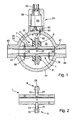
- Fig. 1 shows a magnetic inductive according to the invention
- Fig. 2 shows the measuring tube of Figure 1 in section.
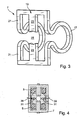
- Fig. 3 shows a view of the Feldleitelements of Fig. 1;
- Fig. 4 shows a sectional view of the measuring tube 1 in the plane of
- Fig. 5 is a view of the flowmeter of Fig. 1;
- Fig. 6 shows a section of the flow sensor shown in Fig. 1
- FIG. 7 shows a view of the sensor of FIG. 6.
- FIG. 1 shows an exemplary embodiment of a sensor according to the invention of a magneto-inductive flowmeter for measuring a flow of a medium through an existing one Piping system.
- the sensor has a measuring tube 1 shown in detail in FIG. 2, the interior of which flows through the medium during measuring operation.
- the measuring tube 1 is inserted via, not shown in Fig. 1, process connections in the existing pipeline system.
- the measuring tube 1 completely made of a plastic.
- thermoplastics such as polyetheretherketone (PEEK), polyvinylidene fluoride (PVDF), polyethylene (PE) or polyamide (PA) are used.
- Plastics are insulators. This offers, inter alia, the advantage that no insulating lining, such as the aforementioned liner, of the measuring tube 1 is required. Accordingly, no medium and no gas between meter tube and lining penetrate.
- the senor comprises a mounted on the measuring tube 1 device 3 for generating a measuring tube 1 at least partially passing magnetic field.
- the device 3 comprises in the illustrated embodiment, two diametrically opposite to the measuring tube 1 fixed coils 5 and a one-piece Feldleitelement 7 made of a magnetically conductive material, which serves to guide the magnetic field outside of the measuring tube 1.
- each holder 9 comprises two mutually parallel arranged directly on the measuring tube 1 integrally formed locking elements 11, which have a straight portion 13 with rectangular cross section, to the ends of a tapered in measuring tube-facing direction shoulder 15 connects.
- the coils 5 are substantially hollow cylindrical and are attached to the two locking elements 11. When assembled, the coils 5 surround the straight portions 13 coaxially and are fixed in position by the adjacent heels 15.
- the Feldleitelement 7 consists of a resilient material and is inserted into the brackets 9. In this case, the Feldleitelement 7 is pushed onto the measuring tube 1 and it is the two middle crossbars 23 inserted into a gap 27 between the two Rastelelementen 11 of the respective holder 9.
- the Feldleitelements 7 is additionally provided at each locking element 11 at the end a in the gap 27 facing in locking lug 29 which engage in the assembled state respectively behind the trunk of the respective E-shaped member 21.
- electrodes 31 are inserted into corresponding holes. This is on the EP 0 892 252 A1 directed. There, a liquid-tight installation of electrodes is described, which is achieved for example in that the electrodes are provided with successive truncated cone-shaped sections in which the material of the measuring tube 1 digs.
- the electrodes 31 inserted into the measuring tube 1 serve to pick up a voltage induced in the medium during measuring operation.
- two electrodes 31 are provided, which are inserted opposite each other in such a way in the measuring tube 1, that an imaginary between the electrodes 31 connecting line perpendicular to an imaginary between the two coils 5 connecting line and thus perpendicular to the magnetic field. 4 shows a sectional drawing of the measuring tube 1 in the plane of the electrodes 31.
- the sensor has a sensor housing 33 made of a plastic, which has a hermetically sealed closed interior 35 has.
- the same material is used here, which is also used for the measuring tube 1.
- the measuring tube 1 is wholly or partially inserted by means of a hermetically sealed connection in the Meßaufêtgeophuse 33 that the interior of the measuring tube 1 inlet and outlet side accessible, and the interior 35 of the Meßerkumblegephinuses 33 with respect to the interior of the measuring tube and the environment of the sensor hermetically is tightly closed. This is particularly possible because the hermetically sealed parts to be joined together, the sensor housing 33 and the measuring tube 1 are both made of plastic.
- the hermetically sealed connections between the affected segments to be connected of the sensor housing 33 and the measuring tube 1 are preferably produced by plastic welding or by gluing.
- the device 3 for generating the magnetic field In the interior 35 of the sensor housing 33 are the device 3 for generating the magnetic field, the connecting lines 37, and connecting lines 39 for the electrodes 31, 32.
- electrical and / or mechanical components such as a suburb electronics, be included.
- the sensor housing 33 shown in FIG. 1 has a hollow cylinder 41, on which on opposite sides an inlet 43 and an outlet 45 for the medium are formed.
- Inlet 43 and outlet 45 are each formed by an integrally formed on the hollow cylinder 41 in the interior of the hollow cylinder 41 opening pipe segment.
- the measuring tube 1 is in this embodiment completely in the sensor housing 33 and is arranged in the hollow cylinder 41 such that it is perpendicular to a longitudinal axis of the hollow cylinder and the inlet 43 connects to the outlet 45.
- a mouth 43 of the inlet 43 and another mouth of the outlet coaxially tightly enclosing recess 47 is provided, in which the respective ends of the measuring tube 1 are inserted such that an inner circumferential surface of the measuring tube 1 is flush with the adjoining inner lateral surfaces the inlet 43 and the outlet 45 closes.
- Both ends of the measuring tube 1 are inserted into the respective recesses 47 by means of a hermetically sealed connection, eg welded or glued.
- a hermetically sealed connection eg welded or glued.
- This connection is produced, for example, by completely fitting the measuring tube 1 with the electrodes 31, 32, the coils 5 and the field-guiding system 7.
- the hollow cylinder 41 is compressed perpendicular to the direction of flow. This leads to an expansion of the hollow cylinder 41 in the direction of flow.
- Measuring tube 1 and hollow cylinder 41 are warmed, for example, and it is that the measuring tube 1 is inserted into the compressed hollow cylinder 41, and there welded or glued.
- the sensor housing 7 comprises two substantially circular disc-shaped cover 49, which are applied by means of a hermetically sealed connection, esp. A plastic weld or a bond, on two opposite annular end faces of the hollow cylinder 41. 5 shows a view of the sensor housing 33.
- the interior 35 of the sensor housing 33 is completely self-contained and closed to the outside by the measuring tube 1 which is hermetically sealed therein.
- the measuring tube 1 which is hermetically sealed therein.
- connection space 51 Adjoining the sensor housing 41 is a connection space 51, the interior 53 of which is surrounded by an outer wall 55 of the housing Sensor housing 41 is completely separated from the interior 35 of the sensor housing 41.
- this outer space 55 of the sensor housing which separates the interior 35 of the sensor housing 41 from the connection space 51, hermetically sealed passages 57 are provided, via which the connection lines 37 of the device 3 for generating the magnetic field and connection lines 39 of the electrodes 31, 32 are led into the connection space 51.
- the passages 57 are preferably just like the electrodes 31, 32 equipped with successive truncated cone-shaped sections in which the material of the outer wall 55 digs.
- the terminal space 51 is preferably formed by a cap-shaped attachment 59 made of a plastic, which is hermetically sealed to a formed on the Meßaufrichgeophuse 41, the bushings 57 surrounding base 61. Again, the same material is preferably used, which is also used for the measuring tube 1 and the sensor housing 41.
- the hermetically sealed connection is preferably a plastic weld or a bond.
- connection lines 37, 39 are guided via the passages 57 into the connection space 51 and are connected there to a connector 63 arranged on the connection space 51, via which they can be contacted from the outside.
- the remaining space in the connection space 53 cavity is preferably filled with a potting compound. In this way, it is ensured that the connection space 53 is protected from the ingress of moisture.
- Fig. 1 may be equipped with a variety of different process connections.
- Fig. 6 shows a section and
- Fig. 7 is a view of the sensor of Fig. 1 in which at the inlet 43 and at the outlet 45 plastic flanges 65 are formed.
- Other types of process connections can also be used and can be formed directly on inlet 43 and outlet 45.
- the process connections directly to mold to the measuring tube.
- a sensor housing that hermetically encloses a portion of the measuring tube between the process connections.
- This housing may, for example, have two housing halves, which are hermetically sealed together, in particular welded or glued.
- the measuring tube is in this case through the housing and is there, where it enters the hermetically sealed into the housing or to connect to the housing, for example, to be welded or glued. This also makes it possible to achieve a hermetically sealed interior of the sensor housing.
Landscapes
- Physics & Mathematics (AREA)
- Fluid Mechanics (AREA)
- General Physics & Mathematics (AREA)
- Electromagnetism (AREA)
- Measuring Volume Flow (AREA)
Applications Claiming Priority (1)
| Application Number | Priority Date | Filing Date | Title |
|---|---|---|---|
| DE200610023915 DE102006023915A1 (de) | 2006-05-19 | 2006-05-19 | Messaufnehmer eines magnetisch induktiven Durchflussmessgeräts |
Publications (2)
| Publication Number | Publication Date |
|---|---|
| EP1857784A2 true EP1857784A2 (fr) | 2007-11-21 |
| EP1857784A3 EP1857784A3 (fr) | 2008-07-23 |
Family
ID=38171634
Family Applications (1)
| Application Number | Title | Priority Date | Filing Date |
|---|---|---|---|
| EP07108382A Withdrawn EP1857784A3 (fr) | 2006-05-19 | 2007-05-16 | Capteur de mesure d'un débitmètre électromagnétique |
Country Status (2)
| Country | Link |
|---|---|
| EP (1) | EP1857784A3 (fr) |
| DE (1) | DE102006023915A1 (fr) |
Cited By (6)
| Publication number | Priority date | Publication date | Assignee | Title |
|---|---|---|---|---|
| DE102008056871A1 (de) * | 2008-11-12 | 2010-06-10 | Abb Technology Ag | Durchflussmessgerät |
| WO2010146007A1 (fr) * | 2009-06-18 | 2010-12-23 | Siemens Aktiengesellschaft | Débitmètre magnéto-inductif et son procédé de fabrication |
| EP2469244A4 (fr) * | 2009-08-18 | 2015-04-08 | Takahata Prec R & D Ct Co Ltd | Débitmètre électromagnétique pour tuyau de conduite et procédé pour sa fabrication |
| WO2016053513A1 (fr) | 2014-09-30 | 2016-04-07 | Rosemount Inc. | Débitmètre magnétique équipé d'un capteur de perméation à la vapeur |
| EP3486618A1 (fr) * | 2008-04-18 | 2019-05-22 | Elster Water Metering Limited | Boîtier pour débitmètre de fluide |
| EP4657030A1 (fr) * | 2024-05-27 | 2025-12-03 | ebm-papst Mulfingen GmbH & Co. KG | Positionnement de capteur |
Families Citing this family (6)
| Publication number | Priority date | Publication date | Assignee | Title |
|---|---|---|---|---|
| DE102008036962A1 (de) * | 2008-08-08 | 2010-02-11 | Endress + Hauser Flowtec Ag | Magnetisch-induktives Durchflussmessgerät mit einer Elektrodenanordnung und Verfahren zu dessen Fertigung |
| DE102008048004A1 (de) * | 2008-09-19 | 2010-04-08 | Abb Technology Ag | Induktive Durchflussmesseinrichtung |
| DE102008057756A1 (de) * | 2008-11-17 | 2010-05-27 | Krohne Ag | Magnetisch-induktives Durchflußmeßgerät |
| DE102012110665A1 (de) * | 2012-11-07 | 2014-05-08 | Endress + Hauser Flowtec Ag | Magnetisch-induktives Durchflussmessgerät und Anordnung |
| DE102014105569B3 (de) * | 2014-04-17 | 2015-08-20 | Endress + Hauser Flowtec Ag | Gehäuse für magnetisch induktives Durchflussmessgerät |
| DE102014113843A1 (de) | 2014-09-24 | 2016-03-24 | Endress+Hauser Flowtec Ag | Messrohr für ein Durchflussmessgerät und ein magnetisch-induktives Durchflussmessgerät |
Family Cites Families (10)
| Publication number | Priority date | Publication date | Assignee | Title |
|---|---|---|---|---|
| US3750468A (en) * | 1971-04-08 | 1973-08-07 | Fischer & Porter Co | Lined flow tube for electromagnetic flowmeter |
| US4631969A (en) * | 1977-02-23 | 1986-12-30 | Fischer & Porter Company | Capacitance-type electrode assemblies for electromagnetic flowmeter |
| DE2744865A1 (de) * | 1977-10-05 | 1979-04-19 | Fischer & Porter Gmbh | Vorrichtung zur messung des stroms einer ein rohrstueck durchfliessenden fluessigkeit |
| DE7923803U1 (de) * | 1979-08-21 | 1981-04-30 | Turbo-Werk Fritz Hammelrath, 5000 Köln | Induktiver durchflussmesser |
| JPS57186116A (en) * | 1981-05-13 | 1982-11-16 | Yokogawa Hokushin Electric Corp | Electromagnetic flow meter transmitter |
| US4470309A (en) * | 1981-07-06 | 1984-09-11 | Tokyo Shibaura Denki Kabushiki Kaisha | Electromagnetic flowmeter |
| DE3401488C1 (de) * | 1984-01-18 | 1985-03-14 | Turbo-Werk Messtechnik GmbH, 5000 Köln | Meßsonde |
| DE3545155C2 (de) * | 1984-12-26 | 1994-03-10 | Toshiba Kawasaki Kk | Elektromagnetisches Durchflußmeßgerät |
| JPH0619285B2 (ja) * | 1987-10-23 | 1994-03-16 | 株式会社日立製作所 | 外筒を有するセラミック導管 |
| GB2333366A (en) * | 1998-01-17 | 1999-07-21 | Caledonian Control Technology | Encapsulated electromagnetic flowmeter |
-
2006
- 2006-05-19 DE DE200610023915 patent/DE102006023915A1/de not_active Withdrawn
-
2007
- 2007-05-16 EP EP07108382A patent/EP1857784A3/fr not_active Withdrawn
Cited By (7)
| Publication number | Priority date | Publication date | Assignee | Title |
|---|---|---|---|---|
| EP3486618A1 (fr) * | 2008-04-18 | 2019-05-22 | Elster Water Metering Limited | Boîtier pour débitmètre de fluide |
| DE102008056871A1 (de) * | 2008-11-12 | 2010-06-10 | Abb Technology Ag | Durchflussmessgerät |
| WO2010146007A1 (fr) * | 2009-06-18 | 2010-12-23 | Siemens Aktiengesellschaft | Débitmètre magnéto-inductif et son procédé de fabrication |
| EP2469244A4 (fr) * | 2009-08-18 | 2015-04-08 | Takahata Prec R & D Ct Co Ltd | Débitmètre électromagnétique pour tuyau de conduite et procédé pour sa fabrication |
| WO2016053513A1 (fr) | 2014-09-30 | 2016-04-07 | Rosemount Inc. | Débitmètre magnétique équipé d'un capteur de perméation à la vapeur |
| EP3201574A4 (fr) * | 2014-09-30 | 2018-07-25 | Micro Motion, Inc. | Débitmètre magnétique équipé d'un capteur de perméation à la vapeur |
| EP4657030A1 (fr) * | 2024-05-27 | 2025-12-03 | ebm-papst Mulfingen GmbH & Co. KG | Positionnement de capteur |
Also Published As
| Publication number | Publication date |
|---|---|
| DE102006023915A1 (de) | 2007-11-22 |
| EP1857784A3 (fr) | 2008-07-23 |
Similar Documents
| Publication | Publication Date | Title |
|---|---|---|
| EP2583067B1 (fr) | Procede de production d'un débitmètre magnéto-inductif | |
| EP2917700B1 (fr) | Débitmètre magnéto-inductif et agencement | |
| EP1522828A1 (fr) | Appareil magnéto-inductif de mesure de milieux en écoulement et son procédé de fabrication | |
| DE3006723A1 (de) | Elektromagnetischer stroemungsmesser | |
| WO2014019888A1 (fr) | Débitmètre magnéto-inductif | |
| EP1522827A1 (fr) | Appareil magnéto-inductif de mesure de milieux en écoulement et son procédé de fabrication | |
| DE102006023915A1 (de) | Messaufnehmer eines magnetisch induktiven Durchflussmessgeräts | |
| DE102014113404A1 (de) | Magnetisch-induktives Durchflussmessgerät mit einem Vierspulen- Magnetsystem | |
| DE102019133461A1 (de) | Magnetisch-induktives Durchflussmessgerät | |
| DE102010032270B4 (de) | Magnetisch-induktives Durchflussmessgerät | |
| DE102009010637A1 (de) | Vorrichtung zur Durchflussmessung | |
| WO2008074742A1 (fr) | Dispositif pour mesurer le débit volumétrique ou massique d'un milieu dans une canalisation | |
| DE102005044677A1 (de) | Magnetisch-induktiver Durchflussmesser mit einer Erdungsscheibe | |
| DE102004057695B4 (de) | Magnetisch induktiver Durchflussmesser mit einem Messrohr aus Kunststoff | |
| DE202015006553U1 (de) | ln-Line-Ultraschall-Durchflusssensor | |
| EP4062129B1 (fr) | Sonde de débit magnéto-inductif | |
| EP1696214A1 (fr) | Débitmètre et procédé d'installation d'un débitmètre | |
| DE102005060208A1 (de) | Messaufnehmer eines magnetisch induktiven Durchflussmessgeräts | |
| DE102009031873A1 (de) | Magnetisch induktiver Durchflussmesser sowie austauschbarer rohrförmiger Einsatz für einen derartigen Durchflussmesser | |
| DE102017220847A1 (de) | Verfahren zum Herstellen eines Leitfähigkeitssensors und Leitfähigkeitssensor | |
| DE102006042062A1 (de) | Die Erfindung betrifft eine Vorrichtung zum Messen des Volumen- oder Massestroms eines Mediums in einer Rohrleitung | |
| EP0990876A1 (fr) | Débitmètre, en particulier débitmètre inductif, et procédé pour sa production | |
| EP4034845A1 (fr) | Débitmètre magnéto-inductif | |
| EP3418707A1 (fr) | Capteur de pression montable | |
| EP1994370B1 (fr) | Équilibrage des potentiels entre un fluide et le capteur de mesure d'un débitmètre |
Legal Events
| Date | Code | Title | Description |
|---|---|---|---|
| PUAI | Public reference made under article 153(3) epc to a published international application that has entered the european phase |
Free format text: ORIGINAL CODE: 0009012 |
|
| AK | Designated contracting states |
Kind code of ref document: A2 Designated state(s): AT BE BG CH CY CZ DE DK EE ES FI FR GB GR HU IE IS IT LI LT LU LV MC MT NL PL PT RO SE SI SK TR |
|
| AX | Request for extension of the european patent |
Extension state: AL BA HR MK YU |
|
| PUAL | Search report despatched |
Free format text: ORIGINAL CODE: 0009013 |
|
| AK | Designated contracting states |
Kind code of ref document: A3 Designated state(s): AT BE BG CH CY CZ DE DK EE ES FI FR GB GR HU IE IS IT LI LT LU LV MC MT NL PL PT RO SE SI SK TR |
|
| AX | Request for extension of the european patent |
Extension state: AL BA HR MK RS |
|
| AKX | Designation fees paid | ||
| STAA | Information on the status of an ep patent application or granted ep patent |
Free format text: STATUS: THE APPLICATION IS DEEMED TO BE WITHDRAWN |
|
| 18D | Application deemed to be withdrawn |
Effective date: 20090124 |
|
| REG | Reference to a national code |
Ref country code: DE Ref legal event code: 8566 |