EP2583067B1 - Procede de production d'un débitmètre magnéto-inductif - Google Patents
Procede de production d'un débitmètre magnéto-inductif Download PDFInfo
- Publication number
- EP2583067B1 EP2583067B1 EP11719252.6A EP11719252A EP2583067B1 EP 2583067 B1 EP2583067 B1 EP 2583067B1 EP 11719252 A EP11719252 A EP 11719252A EP 2583067 B1 EP2583067 B1 EP 2583067B1
- Authority
- EP
- European Patent Office
- Prior art keywords
- electrode
- measuring tube
- plastic
- electromagnetic flowmeter
- fabrication
- Prior art date
- Legal status (The legal status is an assumption and is not a legal conclusion. Google has not performed a legal analysis and makes no representation as to the accuracy of the status listed.)
- Active
Links
- 238000000034 method Methods 0.000 title claims description 28
- 239000004033 plastic Substances 0.000 claims description 57
- 238000007789 sealing Methods 0.000 claims description 38
- 238000004519 manufacturing process Methods 0.000 claims description 18
- 230000000295 complement effect Effects 0.000 claims description 10
- 229920000642 polymer Polymers 0.000 claims description 7
- 239000004020 conductor Substances 0.000 claims description 3
- 238000004382 potting Methods 0.000 claims 3
- 239000007788 liquid Substances 0.000 claims 1
- 230000002093 peripheral effect Effects 0.000 claims 1
- 230000015572 biosynthetic process Effects 0.000 description 7
- 238000005755 formation reaction Methods 0.000 description 7
- 239000000463 material Substances 0.000 description 5
- 238000001746 injection moulding Methods 0.000 description 4
- 238000004023 plastic welding Methods 0.000 description 4
- 238000003466 welding Methods 0.000 description 4
- 238000004873 anchoring Methods 0.000 description 3
- 229910001220 stainless steel Inorganic materials 0.000 description 3
- 239000010935 stainless steel Substances 0.000 description 3
- 239000000126 substance Substances 0.000 description 3
- 238000005266 casting Methods 0.000 description 2
- 230000008878 coupling Effects 0.000 description 2
- 238000010168 coupling process Methods 0.000 description 2
- 238000005859 coupling reaction Methods 0.000 description 2
- 239000012777 electrically insulating material Substances 0.000 description 2
- 238000005538 encapsulation Methods 0.000 description 2
- 238000005516 engineering process Methods 0.000 description 2
- 238000005259 measurement Methods 0.000 description 2
- 238000000465 moulding Methods 0.000 description 2
- BASFCYQUMIYNBI-UHFFFAOYSA-N platinum Chemical compound [Pt] BASFCYQUMIYNBI-UHFFFAOYSA-N 0.000 description 2
- 241000191291 Abies alba Species 0.000 description 1
- 229920002943 EPDM rubber Polymers 0.000 description 1
- 229920002449 FKM Polymers 0.000 description 1
- 239000004696 Poly ether ether ketone Substances 0.000 description 1
- RTAQQCXQSZGOHL-UHFFFAOYSA-N Titanium Chemical compound [Ti] RTAQQCXQSZGOHL-UHFFFAOYSA-N 0.000 description 1
- 238000013459 approach Methods 0.000 description 1
- JUPQTSLXMOCDHR-UHFFFAOYSA-N benzene-1,4-diol;bis(4-fluorophenyl)methanone Chemical compound OC1=CC=C(O)C=C1.C1=CC(F)=CC=C1C(=O)C1=CC=C(F)C=C1 JUPQTSLXMOCDHR-UHFFFAOYSA-N 0.000 description 1
- 239000000919 ceramic Substances 0.000 description 1
- 239000002800 charge carrier Substances 0.000 description 1
- 238000000576 coating method Methods 0.000 description 1
- 230000001419 dependent effect Effects 0.000 description 1
- 238000013461 design Methods 0.000 description 1
- 238000011161 development Methods 0.000 description 1
- 230000018109 developmental process Effects 0.000 description 1
- 238000007598 dipping method Methods 0.000 description 1
- 238000009826 distribution Methods 0.000 description 1
- 239000003651 drinking water Substances 0.000 description 1
- 235000020188 drinking water Nutrition 0.000 description 1
- 230000000694 effects Effects 0.000 description 1
- 230000005520 electrodynamics Effects 0.000 description 1
- 229910000856 hastalloy Inorganic materials 0.000 description 1
- 230000006698 induction Effects 0.000 description 1
- 230000001939 inductive effect Effects 0.000 description 1
- 238000009434 installation Methods 0.000 description 1
- 238000005304 joining Methods 0.000 description 1
- 239000000696 magnetic material Substances 0.000 description 1
- 230000005389 magnetism Effects 0.000 description 1
- 239000000203 mixture Substances 0.000 description 1
- 230000035515 penetration Effects 0.000 description 1
- 229910052697 platinum Inorganic materials 0.000 description 1
- 229920002530 polyetherether ketone Polymers 0.000 description 1
- 238000012545 processing Methods 0.000 description 1
- 238000010079 rubber tapping Methods 0.000 description 1
- 229910052715 tantalum Inorganic materials 0.000 description 1
- GUVRBAGPIYLISA-UHFFFAOYSA-N tantalum atom Chemical compound [Ta] GUVRBAGPIYLISA-UHFFFAOYSA-N 0.000 description 1
- 229920001169 thermoplastic Polymers 0.000 description 1
- 239000004416 thermosoftening plastic Substances 0.000 description 1
- 229910052719 titanium Inorganic materials 0.000 description 1
- 239000010936 titanium Substances 0.000 description 1
- 239000002351 wastewater Substances 0.000 description 1
Images


Classifications
-
- B—PERFORMING OPERATIONS; TRANSPORTING
- B05—SPRAYING OR ATOMISING IN GENERAL; APPLYING FLUENT MATERIALS TO SURFACES, IN GENERAL
- B05D—PROCESSES FOR APPLYING FLUENT MATERIALS TO SURFACES, IN GENERAL
- B05D1/00—Processes for applying liquids or other fluent materials
-
- G—PHYSICS
- G01—MEASURING; TESTING
- G01F—MEASURING VOLUME, VOLUME FLOW, MASS FLOW OR LIQUID LEVEL; METERING BY VOLUME
- G01F1/00—Measuring the volume flow or mass flow of fluid or fluent solid material wherein the fluid passes through a meter in a continuous flow
- G01F1/56—Measuring the volume flow or mass flow of fluid or fluent solid material wherein the fluid passes through a meter in a continuous flow by using electric or magnetic effects
- G01F1/58—Measuring the volume flow or mass flow of fluid or fluent solid material wherein the fluid passes through a meter in a continuous flow by using electric or magnetic effects by electromagnetic flowmeters
- G01F1/584—Measuring the volume flow or mass flow of fluid or fluent solid material wherein the fluid passes through a meter in a continuous flow by using electric or magnetic effects by electromagnetic flowmeters constructions of electrodes, accessories therefor
-
- Y—GENERAL TAGGING OF NEW TECHNOLOGICAL DEVELOPMENTS; GENERAL TAGGING OF CROSS-SECTIONAL TECHNOLOGIES SPANNING OVER SEVERAL SECTIONS OF THE IPC; TECHNICAL SUBJECTS COVERED BY FORMER USPC CROSS-REFERENCE ART COLLECTIONS [XRACs] AND DIGESTS
- Y10—TECHNICAL SUBJECTS COVERED BY FORMER USPC
- Y10T—TECHNICAL SUBJECTS COVERED BY FORMER US CLASSIFICATION
- Y10T29/00—Metal working
- Y10T29/49—Method of mechanical manufacture
- Y10T29/49002—Electrical device making
- Y10T29/49117—Conductor or circuit manufacturing
- Y10T29/49204—Contact or terminal manufacturing
- Y10T29/49208—Contact or terminal manufacturing by assembling plural parts
- Y10T29/4922—Contact or terminal manufacturing by assembling plural parts with molding of insulation
Definitions
- the present invention relates to a method for producing a magneto-inductive flowmeter by encapsulating an elongated electrode with liquefied plastic and a magnetic-inductive flowmeter produced by the method according to the invention.
- Magnetic-inductive flowmeters use the principle of electrodynamic induction for volumetric flow measurement and are known from a variety of publications.
- Charge carriers of the medium moved perpendicularly to a magnetic field induce a measuring voltage in measuring electrodes which are essentially perpendicular to the direction of flow of the medium and perpendicular to the direction of the magnetic field.
- the measuring voltage induced in the measuring electrodes is proportional to the flow velocity of the medium, averaged over the cross section of the measuring tube, ie proportional to the volume flow. If the density of the medium is known, the mass flow in the pipeline or in the measuring tube can be determined.
- the measuring voltage is usually tapped via a pair of measuring electrodes, which is arranged with respect to the coordinate along the measuring tube axis in the region of maximum magnetic field strength and where consequently the maximum measuring voltage is to be expected.
- the electrodes are usually galvanically coupled to the medium; However, magnetic-inductive flowmeters with non-contact capacitive coupling electrodes are also known.
- the measuring tube can either be made of an electrically conductive, non-magnetic material, such as stainless steel, or consist of an electrically insulating material. If the measuring tube is made of an electrically conductive material, then it must be lined in the area coming into contact with the medium with a liner made of an electrically insulating material. Depending on the temperature and medium, the liner consists, for example, of a thermoplastic, a duroplastic or an elastomeric plastic. However, magnetic-inductive flow meters with a ceramic lining are also known.
- An electrode can essentially be subdivided into an electrode head which at least partially comes into contact with a medium which flows through the measuring tube and an electrode shaft which is introduced almost completely into the wall of the measuring tube.
- the electrodes are in addition to the magnet system, the central components of a magnetic-inductive flowmeter. In the design and arrangement of the electrodes, care must be taken that they can be mounted as simply as possible in the measuring tube and that no leakage problems subsequently occur during measuring operation; In addition, the electrodes should be distinguished by a sensitive and at the same time low-interference measurement signal acquisition.
- measuring electrodes which serve to tap a measuring signal
- additional electrodes in the form of reference or ground electrodes are often installed in the measuring tube, which serve to measure an electrical reference potential or to detect partially filled measuring tubes.
- the electrodes usually have elongated electrode shanks, with diversely shaped notches.
- the WO 2009/071615 A2 shows an electrode with an electrode shaft, with a plurality of frusto-conical sealing lips, wherein the diameters of the sealing lips vary in size.
- electrodes together with other components of a magnetic-inductive flowmeter are cast with the measuring tube in a separate or in a common plastic encapsulation.
- the WO 10015534 A1 shows a magnetic-inductive flowmeter with a sensor, wherein the sensor comprises a flowed through by a medium measuring tube, a magnetic system for generating a Magnetic field comprises, at least one introduced into the measuring tube electrode for detecting an electrical voltage, wherein a fastening means is provided, which serves for fixing the electrode to the measuring tube, wherein the fastening means consists at least partially of plastic, and wherein the fastening means by a plastic welding technique is connected to the measuring tube, and a method for manufacturing a magnetic-inductive flowmeter, wherein the magnetic-inductive flowmeter comprises a measuring tube, wherein the measuring tube has at least one bore, wherein an electrode is introduced into the bore, wherein the electrode by means of a plastic Welding technology is attached to the measuring tube.
- the electrode has at least one sealing element which seals the measuring tube in the region of the bore, wherein the sealing element can be partially introduced into a recess of the electrode shaft.
- the sealing element can be partially introduced into a recess of the electrode shaft.
- Fig. 5A of the document DE 10 2007 004 826 A1 shows a detailed view of a multi-part measuring electrode of a flow meter, in which a first measuring electrode part 26 is embedded in a Meßrohrwandung 2. It can be seen at the point 28 a punctiform shape. It can also be seen from FIG. 5A that the measuring tube wall protrudes into this shape.
- the publication WO 2010/015534 A1 discloses a flow meter in which a determination of a measuring electrode by means of a plastic welding technique. The measuring electrode has a preformed recess 13 and an O-ring, which is arranged loosely in the molding.
- the publication WO 2008/059020 A1 discloses a measuring electrode having a Christmas tree structure. Here, barbs projecting laterally out of the electrode body and the mushroom-head structure of the electrode ensure a better sealing effect.
- the object of the invention is to provide a magneto-inductive measuring device with a cost-effective to produce and highly effective sealing electrode assembly.
- the elongated electrode has at least one longitudinal extension along a longitudinal axis, which is greater than a transverse extent of the electrode, perpendicular to the longitudinal axis. In particular, the ratio of longitudinal extent to transverse extent is greater than 2.
- the electrode may first be completely encased in plastic before the excess plastic is removed again. However, a sheathing is preferred the electrode with plastic, wherein at least the electrode head is not covered by plastic. Furthermore, at the opposite end of the electrode head, shaft end of the electrode also no plastic is provided to electrically contact the electrode.
- the elongated electrode is positioned in an embodiment of the invention in the operational magnetic-inductive flowmeter with its longitudinal axis perpendicular to the measuring tube axis in the measuring tube wall.
- the electrode is made with a circumferential circumferential recess, for example made of stainless steel, or even of an electrically conductive plastic. If the electrode has a circular cross-section transverse to the longitudinal axis of the electrode, the recess is radially encircling. If the groove cross-sectionally rectangular, can then be spoken of an annular groove. In other embodiments of the electrode, the cross sections may be elliptical, oval or polygonal. The punctures may also have various cross-sectional shapes, e.g. rectangular or semicircular or sawtooth.
- an elastic sealing ring When an elastic sealing ring is positioned on the electrode, it is sealingly applied to the electrode surface, e.g. clamped on the jacket of a cylindrically shaped electrode, wherein the sealing ring, in this example a so-called O-ring, then an inner, free diameter, less than the diameter of the jacket of the electrode at the position of the sealing ring on the electrode.
- the sealing ring is in particular positioned on the electrode before the electrode is positioned in the tool; but in any case before the electrode is covered with liquefied plastic.
- the sealing ring is positioned in a recess of the electrode, which is provided for receiving the sealing ring and designed accordingly.
- the shape and size of the sealing ring and the first groove are matched; for example, complementary to each other.
- the elastic sealing ring is at least partially covered with plastic.
- the temperature of the plastic is kept below 350 ° C, especially below 200 ° C. processing and material of the plastic and material of the sealing ring are also matched.
- the sealing ring consists for example of EPDM, Viton or Kalrez.
- the sealing ring seals fluid-tight both with respect to the plastic surrounding the electrode and with respect to the electrode itself.
- Further punctures may be provided in the electrode surface, for axial fixation or determination of the electrode or for Leckagewegverinrung. These also have rectangular or semicircular or sawtooth cross sections. At least one of these further cross-sections, if present, at least partially filled with plastic during manufacture.
- the tooth spaces are at least partially filled with plastic.
- an electrode according to the invention has a collar-shaped collar.
- Another example shows an electrode according to the invention with radially encircling formations for anchoring the electrode and for lengthening the leakage paths. In both examples, the formations also be obtained by recesses are made in addition to the formations that make the formations appear only as such.
- the electrode is aligned in the tool, for example by means of a first and second contour.
- the electrode has e.g. a conical electrode head and / or a bore in the opposite shaft end.
- the tool or a core forming the lumen of the measuring tube has the complementary and compatible with the contours of the electrode, i. Contours with the contours of the electrode agree with each other.
- the electrode is so e.g. with its conical electrode head to a complementary conical depression in the core for the, in later operation of the electromagnetic flowmeter flow-guiding, lumen of the measuring tube and thus form-fitting manner connected to the core.
- the electrode can also have a groove instead of a bore in the end opposite the electrode head of the electrode shaft, or can also be aligned by magnetism in the tool and held during the casting process.
- the electrode is encapsulated with plastic, which simultaneously forms the measuring tube.
- the measuring tube in a first method step, is poured with a space provided for the positioning of the electrode and then the electrode inserted into this space and molded with plastic, the prefabricated measuring tube serves as a tool, and the sheath of the electrode with plastic , which is produced in the second process step, is also part of the measuring tube.
- Further embodiments show the electrode encased in plastic, wherein the electrode is used together with the jacket in a bore in the measuring tube wall and, for example, subsequently welded thereto, in particular with ultrasonic welding.
- the electrode is connected to the core by positive locking Aligning the second and fourth complementary contour is positioned to each other, these parts of the measuring tube, for example, two identical half shells, then connected to other parts with each other, in particular welded together cohesively.
- the present invention relates to a method for producing a magneto-inductive flowmeter, in particular the process measuring technology, for determining the flow of a measuring medium through a measuring tube.
- a cross section through an electrode assembly of a magnetic-inductive flowmeter is shown.
- the electrode 1 is introduced into the wall 2 of a measuring tube and has an electrode shaft 3 and an electrode head 4 at least partially wetted by the medium 5 in the measuring operation.
- Measuring substances 5 can be both pure substances and mixtures.
- the electrode head 4, in the region in which it projects into the lumen of the measuring tube, has a conical shape.
- the electrode shaft 3 has a cylindrical basic shape.
- a cross section through the electrode 1 in a plane parallel to the O-ring 6 is approximately circular, within the usual and familiar to a person skilled in the art and manufacturing Tolerances. Other shapes are possible. Oval or elliptical cross-sections promise a better distribution of stress during thermal expansion of the measuring tube.
- a first radial recess 7 is provided in the region of the electrode shaft 3, in which a sealing ring, here the O-ring 6 is positioned.
- the O-ring 6 protrudes slightly beyond the edge of the electrode shaft 3 so that it forms a first sealing step and seals the electrode 1 in the region of the measuring tube wall 2.
- the electrode has a collar 8, with which the electrode 1 terminates.
- the collar 8 is perpendicular from the electrode longitudinal axis 9.
- the electrode 1 in the end remote from the electrode head 4 has a bore 10 into which a plug, not shown, can be introduced. The plug is used for tapping the measured by means of the electrode head 4 in the medium 5 electrical potential.
- the bore 10 continues to serve during the manufacturing process as a second contour for aligning the electrode in the tool. In this sense, the first contour is the conically shaped electrode head 4.
- the electrode 1 is inserted into an injection molding tool.
- the electrode head 4 is positioned in a core in a form complementary to the electrode head 4.
- the core later forms the lumen of the measuring tube, in which the medium 5 flows.
- the electrode 1 is fixed by means of a mandrel in the bore 10 in the electrode shaft 3, before the electrode is encapsulated with plastic.
- the electrode 1 is poured directly into the measuring tube wall 2, which is produced here from a casting.
- the measuring tube wall 2 is made in two or more casts.
- the measuring tube is surrounded at least in the region of the electrodes by a housing, which is not shown here.
- the measuring tube 5, through which a measuring tube 5 flows, is closed in the region of the electrode shaft 3 by a first sealing step, consisting of a radially arranged O-ring 6, in a pressure- and liquid-tight manner.
- the O-ring 6 has the required physical and chemical properties that are necessary for use in typical media such as drinking water and wastewater. Furthermore, the O-ring 6 is specially designed for use in conjunction with plastic materials.
- Typical materials for measuring tubes according to the invention are, for example, PA, PP, PPE, PSU, PPS, PEEK or PVC.
- the electrodes are made of stainless steel, tantalum, Hastelloy, platinum or titanium, for example.
- the O-ring 6 is enclosed in sections by the plastic of the measuring tube wall 2. At the sections where the O-ring 6 rests on the electrode 1 itself, of course, it is not covered by plastic.
- the first recess 7 is also partially filled in here by the plastic of the measuring tube wall 2.
- the O-ring 6 is positioned on the electrode 7, here in the recess 7, before the electrode 1 is positioned in the tool.
- the electrode has further recesses 11, which are filled with the plastic of the measuring tube wall 2.
- formations 12 of the electrode 1 are defined, which serve for the axial anchoring of the electrode 1 along the longitudinal axis 9 in the measuring tube wall 2 and which at the same time extend the leakage paths.
- the punctures 7 and 11 had a rectangular shape in cross section, but many shapes are conceivable, e.g. also with undercut or semicircular for receiving an O-ring 6 with circular cord cross-section.
- the first recess 7 has a depth perpendicular to the longitudinal axis 9 of the electrode 1 and a width parallel to the longitudinal axis 9 of the electrode 1.
- the sealing ring here O-ring 6, has a line thickness in the direction of the longitudinal axis 9 and a line width perpendicular to the longitudinal axis 9 of the electrode 1 on. If the sealing ring, as illustrated in this figure, an O-ring 6, the cord thickness and the cord width is equal and corresponds to the cord diameter of.
- the ratio of cord thickness to puncture width according to one embodiment is at most 0.8 and at least 0.6, in which case the ratio of cord width to penetration depth is at most 1.5 and at least 1.2. Is the sealing ring an O-ring 6, the free area is defined by the inner diameter of the O-ring 6. The sealing ring is thus tightened sealingly on the electrode.
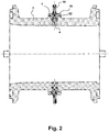
- Fig. 2 shows a non-inventive embodiment of an electrode.
- An electrode 1 has a casing 18 made of plastic, which is inserted into the measuring tube wall 2. This jacket 18 is made, for example, from the same plastic as the measuring tube wall 2.
- the electrode 1 is cast into the jacket 18, wherein the surface of the electrode 1 is at least partially covered with a plastic. At least a free portion of the surface of the electrode 1 is not covered with the plastic, here the electrode head 4 and the opposite end of the electrode 1 with a bore along the longitudinal axis of the electrode 1, in which here a plug 19 for electrical contacting of the electrode. 1 is introduced.
- the potential picked up by the electrodes is transmitted to a measuring and / or operating circuit - not explicitly shown. From the electrical potential, a voltage proportional to the flow rate is derived and from this the flow rate is determined.
- the jacket 18 together with the electrode 1 can be produced separately from the measuring tube, or in a method in a subsequent method step.
- a measuring tube is first manufactured with a space provided for the installation of the electrode with sheath, this space is kept free by a core or a tool. This core is then removed. Thereafter, the electrode 1 can be used together with sheath 18 or only the electrode 1 is used and filled the free space with liquefied plastic. This has the advantage of not having to weld the sheath extra to the measuring tube.
- an electrode can also be produced in a dipping bath, wherein liquefied plastic settles on the electrode and is subsequently machined mechanically to the desired shape.
- Next Coating process however, such processes are more expensive than the described injection molding.
- the sheath 18 forms part of the measuring tube wall 2. At least the part of the measuring tube wall 2 which surrounds and touches the electrode 1 is made of plastic. Now there are other alternatives to a sheath 18 to an electrode 1, which is used in a finished measuring tube and an electrode 1, around which the complete measuring tube is poured.
- the measuring tube wall 2 can have a free space into which the electrode 1 is inserted and which is subsequently filled with plastic, on the other hand, around the electrode 1 only a part of the measuring tube, e.g. a half-shell are then poured, wherein the half-shells subsequently combined to form a measuring tube, e.g. be welded together. Clear manufacturing advantages of the half-shells are obvious to the expert.
- a measuring tube has further components, such as e.g. Flanges. These may or may not be produced in a single process. In particular, flanges can be easily attached to a measuring tube.
- Fig. 3 is a non-inventive electrode 1 together with their, separately produced to the measuring tube casing 18 in section.
- the electrode 1 has a bore 10 for receiving a plug and a plurality of sawtooth-shaped recesses.
- An elastic sealing ring is not provided. Tightness of the connection jacket 18 and electrode 1 is achieved by the plurality of punctures.
- a collar 8 projects perpendicularly from the electrode longitudinal axis 9 in the region of the end of the electrode shaft, opposite the electrode head, for fixing the electrode 1 in the tool and / or the connection with the plastic of the sheath 18.
- the plastic of the casing 18 has similar properties as the plastic of the measuring tube wall, or is even the same.
- the sheath 18 is configured disc-shaped in the region of the collar-shaped collar 8 of the electrode 1.
- This disc 20 of the casing is in the mounted state on a on the Outside of the measuring tube arranged bearing surface is present.
- the support surface is formed by a holder 22.
- the introduced into the measuring tube cylindrical bore is surrounded by the holder 22 in the form of a collar-like approach.
- the holder 22 is located on the outside of the measuring tube.
- the measuring tube consists at least in the region of the bore and the holder 22 made of plastic.
- the casing 18 together with the embedded electrode rests with its disk 20 on the flat support surface which terminates the holder.
- the bearing surface of the disc 20 extends perpendicular to the electrode longitudinal axis and parallel to the longitudinal axis of the measuring tube.
- the disc 20 is connected to the bracket 22 by a plastic welding process.
- the disc additionally has a welding lip 21 along the joining zone on the holder 22.
- the welding lip 21 has a roof-shaped cross section and is fused cohesively to the holder 22. As a result, the bore is sealed pressure and liquid-tight.
- Fig. 4 are sketched various non-inventive electrodes.
- the electrodes in this case have the same basic shape, but differ by their punctures 11.
- Punctooth shape described above
- semicircular recesses 11 and rectangular grooves 11 can be seen.
- other forms for anchoring the electrode and extending the leakage paths are possible, for example, with undercut.
- a sawtooth-shaped groove 7 The groove 7 is bounded by the tooth back 13 and the tooth face 14.
- the free space in between is referred to as a tooth gap 15.
- the point of intersection between tooth back 13 and tooth face 14 of a single sawtooth-shaped recess 7 is called tooth base 16, the point of intersection between tooth back 13 and tooth face 14 of FIG two adjacent sawtooth-shaped recesses 7 is called tooth tip 17th wedge angle we called the angle between the tooth back 13 and tooth face 14.
Landscapes
- Physics & Mathematics (AREA)
- Electromagnetism (AREA)
- Fluid Mechanics (AREA)
- General Physics & Mathematics (AREA)
- Measuring Volume Flow (AREA)
Claims (10)
- Procédé destiné à la fabrication d'un débitmètre magnéto-inductif par le moulage d'une électrode (1) au moyen de plastique liquéfié, l'électrode étant constituée d'un matériau électriquement conducteur et munie d'une première gorge (7) périphérique s'étendant perpendiculairement à une dilatation longitudinale de l'électrode (1),
pour lequel l'électrode (1) est positionnée dans un outil et moulée au moins partiellement au moyen de plastique liquéfié,
pour lequel la première gorge (7) de l'électrode (1) est moulée au moins partiellement au moyen de plastique liquéfié,
caractérisé
en ce qu'une bague d'étanchéité élastique (6) est positionnée dans la première gorge (7) de l'électrode (1) pour le logement de la bague d'étanchéité (6), la bague d'étanchéité élastique (6) étant moulée au moins partiellement au moyen de plastique,
la première gorge étant prévue et conçue pour le logement de la bague d'étanchéité,
la bague d'étanchéité étant positionnée avant le moulage au moyen du plastique liquéfié,
la bague d'étanchéité (6) étant fabriquée à partir d'un polymère et
la température du plastique étant maintenue sous 350 °C pendant le moulage au moins partiel de la bague d'étanchéité (6). - Procédé destiné à la fabrication d'un débitmètre magnéto-inductif selon la revendication 1,
caractérisé
en ce que l'électrode (1) est réalisée avec une section circulaire ou elliptique ou ovale. - Procédé destiné à la fabrication d'un débitmètre magnéto-inductif selon l'une des revendications 1 à 2,
caractérisé
en ce que l'électrode (1) est munie de gorges (11) supplémentaires, lesquelles sont moulées au moins partiellement avec du plastique liquéfié. - Procédé destiné à la fabrication d'un débitmètre magnéto-inductif selon l'une des revendications 1 à 3,
caractérisé
en ce que l'outil présente un troisième contour complémentaire au premier contour de l'électrode (1) et en ce que le positionnement de l'électrode (1) dans l'outil est effectué par un alignement rigide entre le premier contour complémentaire et le troisième contour. - Procédé destiné à la fabrication d'un débitmètre magnéto-inductif selon l'une des revendications 1 à 4,
caractérisé
en ce qu'un tube de mesure est moulé au moyen de plastique liquéfié et en ce qu'un noyau, lequel forme un canal intérieur du tube de mesure, présente un quatrième contour complémentaire au deuxième contour de l'électrode (1), l'électrode (1) étant positionnée contre le noyau par un alignement rigide entre le deuxième contour et le quatrième contour complémentaire. - Procédé destiné à la fabrication d'un débitmètre magnéto-inductif selon l'une des revendications 1 à 4,
caractérisé
en ce que, dans une première étape de procédé, une paroi (2) du tube de mesure (2) est moulée avec le plastique liquéfié et en ce que, dans une deuxième étape de procédé, une gaine est moulée autour de l'électrode (1), dans un espace libre prévu à cette fin dans la paroi (2) du tube de mesure. - Procédé destiné à la fabrication d'un débitmètre magnéto-inductif selon la revendication 6,
caractérisé
en ce que le même plastique est utilisé dans les deux étapes de procédé. - Procédé destiné à la fabrication d'un débitmètre magnéto-inductif selon l'une des revendications 1 à 7,
caractérisé
en ce qu'au moins la première gorge (7) est réalisée avec une section rectangulaire ou une section circulaire. - Procédé destiné à la fabrication d'un débitmètre magnéto-inductif selon l'une des revendications 3 à 8,
caractérisé
en ce qu'au moins une deuxième gorge (11) de l'électrode (1) est réalisée avec une section en forme de dent de scie,
l'électrode (1) étant positionnée dans le tube de mesure de telle sorte qu'un dos de dent (13) allant d'un fond de dent (16) à une pointe de dent (17) de la section en forme de dent de scie pointe en direction d'un canal intérieur du tube de mesure, lequel canal guide l'écoulement. - Débitmètre magnéto-inductif destiné à la mesure du débit volumique ou massique d'un produit dans une conduite, avec un tube de mesure, qui est parcouru par le produit (5) en direction de l'axe longitudinal du tube de mesure, avec un système magnétique, qui est conçu de telle sorte à générer un champ magnétique traversant le tube de mesure pour l'essentiel perpendiculairement à l'axe longitudinal du tube de mesure, avec au moins une électrode de mesure (1) couplée avec le produit, laquelle électrode est disposée dans une zone située pour l'essentiel perpendiculairement au champ magnétique, dans un alésage (10) de la paroi (2) du tube de mesure, caractérisé en ce que le débitmètre magnéto-inductif est disponible avec un procédé selon l'une des revendications 1 à 9.
Applications Claiming Priority (2)
| Application Number | Priority Date | Filing Date | Title |
|---|---|---|---|
| DE102010030229A DE102010030229A1 (de) | 2010-06-17 | 2010-06-17 | Verfahren zur Herstellung eines magnetisch-induktiven Durchflussmessgeräts |
| PCT/EP2011/057592 WO2011157491A1 (fr) | 2010-06-17 | 2011-05-11 | Procédé de fabrication d'un débitmètre magnéto-inductif |
Publications (2)
| Publication Number | Publication Date |
|---|---|
| EP2583067A1 EP2583067A1 (fr) | 2013-04-24 |
| EP2583067B1 true EP2583067B1 (fr) | 2019-07-03 |
Family
ID=44546019
Family Applications (1)
| Application Number | Title | Priority Date | Filing Date |
|---|---|---|---|
| EP11719252.6A Active EP2583067B1 (fr) | 2010-06-17 | 2011-05-11 | Procede de production d'un débitmètre magnéto-inductif |
Country Status (4)
| Country | Link |
|---|---|
| US (1) | US9440253B2 (fr) |
| EP (1) | EP2583067B1 (fr) |
| DE (1) | DE102010030229A1 (fr) |
| WO (1) | WO2011157491A1 (fr) |
Cited By (1)
| Publication number | Priority date | Publication date | Assignee | Title |
|---|---|---|---|---|
| CN109931992A (zh) * | 2017-12-15 | 2019-06-25 | 阿自倍尔株式会社 | 电磁流量计的电位检测用电极 |
Families Citing this family (17)
| Publication number | Priority date | Publication date | Assignee | Title |
|---|---|---|---|---|
| DE102008036962A1 (de) * | 2008-08-08 | 2010-02-11 | Endress + Hauser Flowtec Ag | Magnetisch-induktives Durchflussmessgerät mit einer Elektrodenanordnung und Verfahren zu dessen Fertigung |
| US9068869B2 (en) * | 2013-03-14 | 2015-06-30 | Rosemount Inc. | Magnetic flowmeter with bonded PTFE electrodes |
| DE102015116676A1 (de) * | 2015-01-20 | 2016-07-21 | Krohne Ag | Magnetisch-induktives Durchflussmessgerät und Verfahren zum Herstellen einer Messelektrode |
| JP6756659B2 (ja) * | 2017-04-28 | 2020-09-16 | 愛知時計電機株式会社 | 電磁流量計 |
| JP6756658B2 (ja) * | 2017-04-28 | 2020-09-16 | 愛知時計電機株式会社 | 電磁流量計 |
| JP6756660B2 (ja) * | 2017-04-28 | 2020-09-16 | 愛知時計電機株式会社 | 電磁流量計 |
| JP6746236B2 (ja) * | 2017-04-28 | 2020-08-26 | 愛知時計電機株式会社 | 電磁流量計 |
| WO2018198418A1 (fr) * | 2017-04-28 | 2018-11-01 | 愛知時計電機株式会社 | Débitmètre électromagnétique |
| JP6768591B2 (ja) * | 2017-04-28 | 2020-10-14 | 愛知時計電機株式会社 | 電磁流量計 |
| JP6741622B2 (ja) * | 2017-04-28 | 2020-08-19 | 愛知時計電機株式会社 | 電磁流量計 |
| JP6746237B2 (ja) * | 2017-04-28 | 2020-08-26 | 愛知時計電機株式会社 | 電磁流量計 |
| DE102017115149A1 (de) * | 2017-07-06 | 2019-01-10 | Endress + Hauser Flowtec Ag | Verfahren zum Herstellen eines magnetisch-induktiven Durchflussmessgeräts und ein magnetisch-induktives Durchflussmessgerät |
| JP6940392B2 (ja) * | 2017-12-15 | 2021-09-29 | アズビル株式会社 | 電磁流量計の電位検出用電極 |
| JP6970001B2 (ja) * | 2017-12-15 | 2021-11-24 | アズビル株式会社 | 電磁流量計の電位検出用電極 |
| IT201800002753A1 (it) * | 2018-02-16 | 2019-08-16 | Eltek Spa | Dispositivo di rilevazione e/o controllo per apparecchi o sistemi a conduzione di liquido |
| CN113483834A (zh) * | 2021-07-22 | 2021-10-08 | 西尼尔(南京)过程控制有限公司 | 浆液电磁流量计的抗噪电极及其制备方法 |
| DE102022106671A1 (de) | 2022-03-22 | 2023-09-28 | Endress+Hauser SE+Co. KG | Füllstandmessgerät |
Citations (1)
| Publication number | Priority date | Publication date | Assignee | Title |
|---|---|---|---|---|
| US20090104521A1 (en) * | 2005-05-17 | 2009-04-23 | Norifumi Yasuda | Storage battery and insulating material and battery container using the same |
Family Cites Families (15)
| Publication number | Priority date | Publication date | Assignee | Title |
|---|---|---|---|---|
| DE1098727B (de) | 1959-10-22 | 1961-02-02 | Siemens Ag | Elektrodendurchfuehrung fuer die induktive Durchflussmessung |
| DE3004870C2 (de) | 1980-02-09 | 1984-08-30 | Eckardt Ag, 7000 Stuttgart | Meßelektrode für magnetische Durchflußmesser |
| JPS59168323A (ja) * | 1983-03-16 | 1984-09-22 | Yamatake Honeywell Co Ltd | 電磁流量計 |
| US4774844A (en) * | 1987-06-25 | 1988-10-04 | Fischer & Porter Co. | Encapsulated electromagnetic flowmeter |
| JP2599322B2 (ja) * | 1991-10-09 | 1997-04-09 | 山武ハネウエル株式会社 | 電磁流量計用電極の製造方法 |
| DE19535998A1 (de) * | 1995-09-27 | 1997-04-03 | Ketelsen Broder | Induktiver Durchflußmesser |
| US5847287A (en) * | 1997-01-21 | 1998-12-08 | Elsag International N.V. | Electromagnetic flowmeter with self-sealing electrodes |
| US7055396B1 (en) * | 2005-03-28 | 2006-06-06 | George Fischer Signet, Inc. | Sensor assembly for magnetic flowmeter and method of manufacture |
| DE102005030193A1 (de) * | 2005-06-29 | 2007-01-04 | Abb Patent Gmbh | Verfahren zum Einsetzen von Messelektroden bei einem magnetisch-induktiven Durchflussmesser |
| DE102006054635A1 (de) | 2006-11-17 | 2008-05-21 | Endress + Hauser Flowtec Ag | Vorrichtung zum Messen des Volumen- oder Massestroms eines Mediums in einer Rohrleitung |
| DE102007004826B4 (de) | 2007-01-31 | 2009-06-18 | Ifm Electronic Gmbh | Messvorrichtung für ein magnetisch induktives Durchflussmessgerät und Durchflussmessgerät |
| DE102007058898A1 (de) | 2007-12-05 | 2009-06-10 | Endress + Hauser Flowtec Ag | Elektrode für ein magnetisch-induktives Durchflussmessgerät |
| DE102008036962A1 (de) * | 2008-08-08 | 2010-02-11 | Endress + Hauser Flowtec Ag | Magnetisch-induktives Durchflussmessgerät mit einer Elektrodenanordnung und Verfahren zu dessen Fertigung |
| DE102008038161A1 (de) | 2008-08-18 | 2010-03-04 | Abb Technology Ag | Durchflussmesseinrichtung |
| DE102008038162A1 (de) | 2008-08-18 | 2010-03-04 | Abb Technology Ag | Durchflussmesseinrichtung, sowie Verfahren zur Herstellung derselben |
-
2010
- 2010-06-17 DE DE102010030229A patent/DE102010030229A1/de not_active Withdrawn
-
2011
- 2011-05-11 US US13/703,830 patent/US9440253B2/en not_active Expired - Fee Related
- 2011-05-11 WO PCT/EP2011/057592 patent/WO2011157491A1/fr not_active Ceased
- 2011-05-11 EP EP11719252.6A patent/EP2583067B1/fr active Active
Patent Citations (1)
| Publication number | Priority date | Publication date | Assignee | Title |
|---|---|---|---|---|
| US20090104521A1 (en) * | 2005-05-17 | 2009-04-23 | Norifumi Yasuda | Storage battery and insulating material and battery container using the same |
Cited By (3)
| Publication number | Priority date | Publication date | Assignee | Title |
|---|---|---|---|---|
| CN109931992A (zh) * | 2017-12-15 | 2019-06-25 | 阿自倍尔株式会社 | 电磁流量计的电位检测用电极 |
| CN109931992B (zh) * | 2017-12-15 | 2020-12-29 | 阿自倍尔株式会社 | 电磁流量计的电位检测用电极 |
| US10996087B2 (en) | 2017-12-15 | 2021-05-04 | Azbil Corporation | Electropotential detection electrode of electromagnetic flow meter |
Also Published As
| Publication number | Publication date |
|---|---|
| WO2011157491A1 (fr) | 2011-12-22 |
| US9440253B2 (en) | 2016-09-13 |
| DE102010030229A1 (de) | 2011-12-22 |
| EP2583067A1 (fr) | 2013-04-24 |
| US20130086993A1 (en) | 2013-04-11 |
Similar Documents
| Publication | Publication Date | Title |
|---|---|---|
| EP2583067A1 (fr) | Procédé de fabrication d'un débitmètre magnéto-inductif | |
| EP2700912B1 (fr) | Appareil de mesure de débit à induction magnétique et son procédé de fabrication | |
| EP2012096A1 (fr) | Capteur de débit magnétique-inductif | |
| EP4006500B1 (fr) | Tube de mesure pour un appareil de mesure ou appareil de mesure formé au moyen d'un tel tube de mesure, ainsi que procédé de fabrication pour un tel tube de mesure | |
| EP3025127B1 (fr) | Débitmètre | |
| EP1151251B1 (fr) | Debitmetre electromagnetique et procede permettant de le produire | |
| WO2016041724A1 (fr) | Procédé de fabrication d'un débitmètre à induction magnétique de section transversale réduite | |
| WO1984002976A1 (fr) | Transducteur pour debitmetres a induction magnetique | |
| DE202009011310U1 (de) | Ultraschalldurchflussmesser mit Universal-Sensorträger | |
| WO2014053325A2 (fr) | Capteur de température et débitmètre | |
| DE102018130793B4 (de) | Magnetisch-induktives Durchflussmessgerät | |
| EP3648943B1 (fr) | Procédé pour la fabrication d'un débitmètre à induction magnétique et débitmètre à induction magnétique | |
| DE102004057695B4 (de) | Magnetisch induktiver Durchflussmesser mit einem Messrohr aus Kunststoff | |
| EP3139138A1 (fr) | Vanne de debitmetre | |
| DE102005044677A1 (de) | Magnetisch-induktiver Durchflussmesser mit einer Erdungsscheibe | |
| DE10358268A1 (de) | Magnetisch-induktiver Durchflußaufnehmer und Verfahren zu dessen Herstellung | |
| DE102006008451B4 (de) | Magnetisch-induktiver Durchflussmesser mit einem Messrohr aus Metall | |
| EP2934754B1 (fr) | Système de mesure comprenant un élément support et un capteur | |
| EP1692465A1 (fr) | Capteur de debit magneto-inductif et procede de fabrication | |
| EP1696214A1 (fr) | Débitmètre et procédé d'installation d'un débitmètre | |
| DE102005060208A1 (de) | Messaufnehmer eines magnetisch induktiven Durchflussmessgeräts | |
| DE102004053065A1 (de) | Magnetisch induktiver Durchflussmesser | |
| DE102015107119A1 (de) | Messrohr und Magnetisch-induktives Durchflussmessgerät | |
| EP3870938B1 (fr) | Débitmètre magnetique-inductif | |
| DE102016123123A1 (de) | Magnetisch-induktives Durchflussmessgerät |
Legal Events
| Date | Code | Title | Description |
|---|---|---|---|
| PUAI | Public reference made under article 153(3) epc to a published international application that has entered the european phase |
Free format text: ORIGINAL CODE: 0009012 |
|
| 17P | Request for examination filed |
Effective date: 20121122 |
|
| AK | Designated contracting states |
Kind code of ref document: A1 Designated state(s): AL AT BE BG CH CY CZ DE DK EE ES FI FR GB GR HR HU IE IS IT LI LT LU LV MC MK MT NL NO PL PT RO RS SE SI SK SM TR |
|
| DAX | Request for extension of the european patent (deleted) | ||
| STAA | Information on the status of an ep patent application or granted ep patent |
Free format text: STATUS: EXAMINATION IS IN PROGRESS |
|
| 17Q | First examination report despatched |
Effective date: 20180207 |
|
| GRAP | Despatch of communication of intention to grant a patent |
Free format text: ORIGINAL CODE: EPIDOSNIGR1 |
|
| STAA | Information on the status of an ep patent application or granted ep patent |
Free format text: STATUS: GRANT OF PATENT IS INTENDED |
|
| INTG | Intention to grant announced |
Effective date: 20190125 |
|
| GRAS | Grant fee paid |
Free format text: ORIGINAL CODE: EPIDOSNIGR3 |
|
| GRAA | (expected) grant |
Free format text: ORIGINAL CODE: 0009210 |
|
| STAA | Information on the status of an ep patent application or granted ep patent |
Free format text: STATUS: THE PATENT HAS BEEN GRANTED |
|
| AK | Designated contracting states |
Kind code of ref document: B1 Designated state(s): AL AT BE BG CH CY CZ DE DK EE ES FI FR GB GR HR HU IE IS IT LI LT LU LV MC MK MT NL NO PL PT RO RS SE SI SK SM TR |
|
| REG | Reference to a national code |
Ref country code: GB Ref legal event code: FG4D Free format text: NOT ENGLISH |
|
| REG | Reference to a national code |
Ref country code: CH Ref legal event code: EP Ref country code: AT Ref legal event code: REF Ref document number: 1151566 Country of ref document: AT Kind code of ref document: T Effective date: 20190715 |
|
| REG | Reference to a national code |
Ref country code: IE Ref legal event code: FG4D Free format text: LANGUAGE OF EP DOCUMENT: GERMAN |
|
| REG | Reference to a national code |
Ref country code: DE Ref legal event code: R096 Ref document number: 502011015865 Country of ref document: DE |
|
| REG | Reference to a national code |
Ref country code: NL Ref legal event code: FP |
|
| REG | Reference to a national code |
Ref country code: LT Ref legal event code: MG4D |
|
| PG25 | Lapsed in a contracting state [announced via postgrant information from national office to epo] |
Ref country code: HR Free format text: LAPSE BECAUSE OF FAILURE TO SUBMIT A TRANSLATION OF THE DESCRIPTION OR TO PAY THE FEE WITHIN THE PRESCRIBED TIME-LIMIT Effective date: 20190703 Ref country code: PT Free format text: LAPSE BECAUSE OF FAILURE TO SUBMIT A TRANSLATION OF THE DESCRIPTION OR TO PAY THE FEE WITHIN THE PRESCRIBED TIME-LIMIT Effective date: 20191104 Ref country code: LT Free format text: LAPSE BECAUSE OF FAILURE TO SUBMIT A TRANSLATION OF THE DESCRIPTION OR TO PAY THE FEE WITHIN THE PRESCRIBED TIME-LIMIT Effective date: 20190703 Ref country code: FI Free format text: LAPSE BECAUSE OF FAILURE TO SUBMIT A TRANSLATION OF THE DESCRIPTION OR TO PAY THE FEE WITHIN THE PRESCRIBED TIME-LIMIT Effective date: 20190703 Ref country code: SE Free format text: LAPSE BECAUSE OF FAILURE TO SUBMIT A TRANSLATION OF THE DESCRIPTION OR TO PAY THE FEE WITHIN THE PRESCRIBED TIME-LIMIT Effective date: 20190703 Ref country code: CZ Free format text: LAPSE BECAUSE OF FAILURE TO SUBMIT A TRANSLATION OF THE DESCRIPTION OR TO PAY THE FEE WITHIN THE PRESCRIBED TIME-LIMIT Effective date: 20190703 Ref country code: NO Free format text: LAPSE BECAUSE OF FAILURE TO SUBMIT A TRANSLATION OF THE DESCRIPTION OR TO PAY THE FEE WITHIN THE PRESCRIBED TIME-LIMIT Effective date: 20191003 Ref country code: BG Free format text: LAPSE BECAUSE OF FAILURE TO SUBMIT A TRANSLATION OF THE DESCRIPTION OR TO PAY THE FEE WITHIN THE PRESCRIBED TIME-LIMIT Effective date: 20191003 |
|
| PG25 | Lapsed in a contracting state [announced via postgrant information from national office to epo] |
Ref country code: RS Free format text: LAPSE BECAUSE OF FAILURE TO SUBMIT A TRANSLATION OF THE DESCRIPTION OR TO PAY THE FEE WITHIN THE PRESCRIBED TIME-LIMIT Effective date: 20190703 Ref country code: IS Free format text: LAPSE BECAUSE OF FAILURE TO SUBMIT A TRANSLATION OF THE DESCRIPTION OR TO PAY THE FEE WITHIN THE PRESCRIBED TIME-LIMIT Effective date: 20191103 Ref country code: LV Free format text: LAPSE BECAUSE OF FAILURE TO SUBMIT A TRANSLATION OF THE DESCRIPTION OR TO PAY THE FEE WITHIN THE PRESCRIBED TIME-LIMIT Effective date: 20190703 Ref country code: ES Free format text: LAPSE BECAUSE OF FAILURE TO SUBMIT A TRANSLATION OF THE DESCRIPTION OR TO PAY THE FEE WITHIN THE PRESCRIBED TIME-LIMIT Effective date: 20190703 Ref country code: AL Free format text: LAPSE BECAUSE OF FAILURE TO SUBMIT A TRANSLATION OF THE DESCRIPTION OR TO PAY THE FEE WITHIN THE PRESCRIBED TIME-LIMIT Effective date: 20190703 Ref country code: GR Free format text: LAPSE BECAUSE OF FAILURE TO SUBMIT A TRANSLATION OF THE DESCRIPTION OR TO PAY THE FEE WITHIN THE PRESCRIBED TIME-LIMIT Effective date: 20191004 |
|
| PG25 | Lapsed in a contracting state [announced via postgrant information from national office to epo] |
Ref country code: TR Free format text: LAPSE BECAUSE OF FAILURE TO SUBMIT A TRANSLATION OF THE DESCRIPTION OR TO PAY THE FEE WITHIN THE PRESCRIBED TIME-LIMIT Effective date: 20190703 |
|
| PG25 | Lapsed in a contracting state [announced via postgrant information from national office to epo] |
Ref country code: DK Free format text: LAPSE BECAUSE OF FAILURE TO SUBMIT A TRANSLATION OF THE DESCRIPTION OR TO PAY THE FEE WITHIN THE PRESCRIBED TIME-LIMIT Effective date: 20190703 Ref country code: EE Free format text: LAPSE BECAUSE OF FAILURE TO SUBMIT A TRANSLATION OF THE DESCRIPTION OR TO PAY THE FEE WITHIN THE PRESCRIBED TIME-LIMIT Effective date: 20190703 Ref country code: PL Free format text: LAPSE BECAUSE OF FAILURE TO SUBMIT A TRANSLATION OF THE DESCRIPTION OR TO PAY THE FEE WITHIN THE PRESCRIBED TIME-LIMIT Effective date: 20190703 Ref country code: RO Free format text: LAPSE BECAUSE OF FAILURE TO SUBMIT A TRANSLATION OF THE DESCRIPTION OR TO PAY THE FEE WITHIN THE PRESCRIBED TIME-LIMIT Effective date: 20190703 Ref country code: IT Free format text: LAPSE BECAUSE OF FAILURE TO SUBMIT A TRANSLATION OF THE DESCRIPTION OR TO PAY THE FEE WITHIN THE PRESCRIBED TIME-LIMIT Effective date: 20190703 |
|
| PG25 | Lapsed in a contracting state [announced via postgrant information from national office to epo] |
Ref country code: IS Free format text: LAPSE BECAUSE OF FAILURE TO SUBMIT A TRANSLATION OF THE DESCRIPTION OR TO PAY THE FEE WITHIN THE PRESCRIBED TIME-LIMIT Effective date: 20200224 Ref country code: SM Free format text: LAPSE BECAUSE OF FAILURE TO SUBMIT A TRANSLATION OF THE DESCRIPTION OR TO PAY THE FEE WITHIN THE PRESCRIBED TIME-LIMIT Effective date: 20190703 Ref country code: SK Free format text: LAPSE BECAUSE OF FAILURE TO SUBMIT A TRANSLATION OF THE DESCRIPTION OR TO PAY THE FEE WITHIN THE PRESCRIBED TIME-LIMIT Effective date: 20190703 |
|
| REG | Reference to a national code |
Ref country code: DE Ref legal event code: R097 Ref document number: 502011015865 Country of ref document: DE |
|
| PLBE | No opposition filed within time limit |
Free format text: ORIGINAL CODE: 0009261 |
|
| STAA | Information on the status of an ep patent application or granted ep patent |
Free format text: STATUS: NO OPPOSITION FILED WITHIN TIME LIMIT |
|
| PG2D | Information on lapse in contracting state deleted |
Ref country code: IS |
|
| 26N | No opposition filed |
Effective date: 20200603 |
|
| PG25 | Lapsed in a contracting state [announced via postgrant information from national office to epo] |
Ref country code: SI Free format text: LAPSE BECAUSE OF FAILURE TO SUBMIT A TRANSLATION OF THE DESCRIPTION OR TO PAY THE FEE WITHIN THE PRESCRIBED TIME-LIMIT Effective date: 20190703 |
|
| PG25 | Lapsed in a contracting state [announced via postgrant information from national office to epo] |
Ref country code: LI Free format text: LAPSE BECAUSE OF NON-PAYMENT OF DUE FEES Effective date: 20200531 Ref country code: MC Free format text: LAPSE BECAUSE OF FAILURE TO SUBMIT A TRANSLATION OF THE DESCRIPTION OR TO PAY THE FEE WITHIN THE PRESCRIBED TIME-LIMIT Effective date: 20190703 Ref country code: CH Free format text: LAPSE BECAUSE OF NON-PAYMENT OF DUE FEES Effective date: 20200531 |
|
| REG | Reference to a national code |
Ref country code: BE Ref legal event code: MM Effective date: 20200531 |
|
| PG25 | Lapsed in a contracting state [announced via postgrant information from national office to epo] |
Ref country code: LU Free format text: LAPSE BECAUSE OF NON-PAYMENT OF DUE FEES Effective date: 20200511 |
|
| PG25 | Lapsed in a contracting state [announced via postgrant information from national office to epo] |
Ref country code: IE Free format text: LAPSE BECAUSE OF NON-PAYMENT OF DUE FEES Effective date: 20200511 |
|
| PG25 | Lapsed in a contracting state [announced via postgrant information from national office to epo] |
Ref country code: BE Free format text: LAPSE BECAUSE OF NON-PAYMENT OF DUE FEES Effective date: 20200531 |
|
| REG | Reference to a national code |
Ref country code: AT Ref legal event code: MM01 Ref document number: 1151566 Country of ref document: AT Kind code of ref document: T Effective date: 20200511 |
|
| PGFP | Annual fee paid to national office [announced via postgrant information from national office to epo] |
Ref country code: FR Payment date: 20210525 Year of fee payment: 11 Ref country code: NL Payment date: 20210519 Year of fee payment: 11 |
|
| PG25 | Lapsed in a contracting state [announced via postgrant information from national office to epo] |
Ref country code: AT Free format text: LAPSE BECAUSE OF NON-PAYMENT OF DUE FEES Effective date: 20200511 |
|
| PGFP | Annual fee paid to national office [announced via postgrant information from national office to epo] |
Ref country code: GB Payment date: 20210525 Year of fee payment: 11 |
|
| PG25 | Lapsed in a contracting state [announced via postgrant information from national office to epo] |
Ref country code: MT Free format text: LAPSE BECAUSE OF FAILURE TO SUBMIT A TRANSLATION OF THE DESCRIPTION OR TO PAY THE FEE WITHIN THE PRESCRIBED TIME-LIMIT Effective date: 20190703 Ref country code: CY Free format text: LAPSE BECAUSE OF FAILURE TO SUBMIT A TRANSLATION OF THE DESCRIPTION OR TO PAY THE FEE WITHIN THE PRESCRIBED TIME-LIMIT Effective date: 20190703 |
|
| PG25 | Lapsed in a contracting state [announced via postgrant information from national office to epo] |
Ref country code: MK Free format text: LAPSE BECAUSE OF FAILURE TO SUBMIT A TRANSLATION OF THE DESCRIPTION OR TO PAY THE FEE WITHIN THE PRESCRIBED TIME-LIMIT Effective date: 20190703 |
|
| PGFP | Annual fee paid to national office [announced via postgrant information from national office to epo] |
Ref country code: DE Payment date: 20220519 Year of fee payment: 12 |
|
| REG | Reference to a national code |
Ref country code: NL Ref legal event code: MM Effective date: 20220601 |
|
| GBPC | Gb: european patent ceased through non-payment of renewal fee |
Effective date: 20220511 |
|
| PG25 | Lapsed in a contracting state [announced via postgrant information from national office to epo] |
Ref country code: FR Free format text: LAPSE BECAUSE OF NON-PAYMENT OF DUE FEES Effective date: 20220531 |
|
| PG25 | Lapsed in a contracting state [announced via postgrant information from national office to epo] |
Ref country code: GB Free format text: LAPSE BECAUSE OF NON-PAYMENT OF DUE FEES Effective date: 20220511 |
|
| PG25 | Lapsed in a contracting state [announced via postgrant information from national office to epo] |
Ref country code: NL Free format text: LAPSE BECAUSE OF NON-PAYMENT OF DUE FEES Effective date: 20220601 |
|
| REG | Reference to a national code |
Ref country code: DE Ref legal event code: R119 Ref document number: 502011015865 Country of ref document: DE |
|
| PG25 | Lapsed in a contracting state [announced via postgrant information from national office to epo] |
Ref country code: DE Free format text: LAPSE BECAUSE OF NON-PAYMENT OF DUE FEES Effective date: 20231201 |