EP1858143A2 - Commutation d'alimentation électrique, appareil électronique, et procédé de commande de la commutation du circuit d'alimentation - Google Patents
Commutation d'alimentation électrique, appareil électronique, et procédé de commande de la commutation du circuit d'alimentation Download PDFInfo
- Publication number
- EP1858143A2 EP1858143A2 EP07108387A EP07108387A EP1858143A2 EP 1858143 A2 EP1858143 A2 EP 1858143A2 EP 07108387 A EP07108387 A EP 07108387A EP 07108387 A EP07108387 A EP 07108387A EP 1858143 A2 EP1858143 A2 EP 1858143A2
- Authority
- EP
- European Patent Office
- Prior art keywords
- power supply
- switching
- square wave
- voltage
- switching element
- Prior art date
- Legal status (The legal status is an assumption and is not a legal conclusion. Google has not performed a legal analysis and makes no representation as to the accuracy of the status listed.)
- Withdrawn
Links
Images



Classifications
-
- H—ELECTRICITY
- H02—GENERATION; CONVERSION OR DISTRIBUTION OF ELECTRIC POWER
- H02M—APPARATUS FOR CONVERSION BETWEEN AC AND AC, BETWEEN AC AND DC, OR BETWEEN DC AND DC, AND FOR USE WITH MAINS OR SIMILAR POWER SUPPLY SYSTEMS; CONVERSION OF DC OR AC INPUT POWER INTO SURGE OUTPUT POWER; CONTROL OR REGULATION THEREOF
- H02M3/00—Conversion of DC power input into DC power output
- H02M3/02—Conversion of DC power input into DC power output without intermediate conversion into AC
- H02M3/04—Conversion of DC power input into DC power output without intermediate conversion into AC by static converters
- H02M3/10—Conversion of DC power input into DC power output without intermediate conversion into AC by static converters using discharge tubes with control electrode or semiconductor devices with control electrode
- H02M3/145—Conversion of DC power input into DC power output without intermediate conversion into AC by static converters using discharge tubes with control electrode or semiconductor devices with control electrode using devices of a triode or transistor type requiring continuous application of a control signal
- H02M3/155—Conversion of DC power input into DC power output without intermediate conversion into AC by static converters using discharge tubes with control electrode or semiconductor devices with control electrode using devices of a triode or transistor type requiring continuous application of a control signal using semiconductor devices only
-
- H—ELECTRICITY
- H02—GENERATION; CONVERSION OR DISTRIBUTION OF ELECTRIC POWER
- H02M—APPARATUS FOR CONVERSION BETWEEN AC AND AC, BETWEEN AC AND DC, OR BETWEEN DC AND DC, AND FOR USE WITH MAINS OR SIMILAR POWER SUPPLY SYSTEMS; CONVERSION OF DC OR AC INPUT POWER INTO SURGE OUTPUT POWER; CONTROL OR REGULATION THEREOF
- H02M3/00—Conversion of DC power input into DC power output
- H02M3/02—Conversion of DC power input into DC power output without intermediate conversion into AC
- H02M3/04—Conversion of DC power input into DC power output without intermediate conversion into AC by static converters
- H02M3/10—Conversion of DC power input into DC power output without intermediate conversion into AC by static converters using discharge tubes with control electrode or semiconductor devices with control electrode
- H02M3/145—Conversion of DC power input into DC power output without intermediate conversion into AC by static converters using discharge tubes with control electrode or semiconductor devices with control electrode using devices of a triode or transistor type requiring continuous application of a control signal
- H02M3/155—Conversion of DC power input into DC power output without intermediate conversion into AC by static converters using discharge tubes with control electrode or semiconductor devices with control electrode using devices of a triode or transistor type requiring continuous application of a control signal using semiconductor devices only
- H02M3/156—Conversion of DC power input into DC power output without intermediate conversion into AC by static converters using discharge tubes with control electrode or semiconductor devices with control electrode using devices of a triode or transistor type requiring continuous application of a control signal using semiconductor devices only with automatic control of output voltage or current, e.g. switching regulators
-
- G—PHYSICS
- G05—CONTROLLING; REGULATING
- G05F—SYSTEMS FOR REGULATING ELECTRIC OR MAGNETIC VARIABLES
- G05F1/00—Automatic systems in which deviations of an electric quantity from one or more predetermined values are detected at the output of the system and fed back to a device within the system to restore the detected quantity to its predetermined value or values, i.e. retroactive systems
- G05F1/10—Regulating voltage or current
Definitions
- the present invention relates to a switching power supply device for converting the voltage of a direct-current power supply, an electronic apparatus equipped with the power supply device, and a method of controlling the switching power supply circuit applied to control of the power supply device.
- the switching power supply devices have widely been used as the power supply circuits (devices) of various electronic apparatuses.
- a switching element for switching the input power supply at high speed and the output power supply is obtained by smoothing the switching output of the switching element.
- the configuration for switching operation of the switching element is arranged to perform the on-off control by a PWM wave.
- the PWM wave for performing the on-off control of the switching element is arranged to be generated based on the result of comparison between the output voltage obtained by smoothing the switching output and the input voltage. For example, it is arranged that the duty cycle of the PWM wave to be generated is varied based on the comparison so that the output voltage becomes a specified value.
- JP-A-2000-308335 there is disclosed the configuration of a switching power supply device.
- the switching power supply device in the related art since the switching power supply device in the related art has the configuration of obtaining a desired output voltage by changing the duty cycle of the PWM wave for controlling the switching element, it is required to generate the PWM wave with variable duty cycle, and accordingly, the configuration of controlling the switching element has been problematically complicated.
- a configuration of generating a square wave with constant duty cycle to control switching by the switching element is adopted. Further, it is arranged to watch the voltage of the output obtained by smoothing the output of the switching element to control the generation period of the square wave so that the output voltage is organized within a certain range.
- the output voltage within a required voltage range can be obtained.
- the circuit for generating the square wave with a constant duty cycle by providing the circuit for generating the square wave with a constant duty cycle, an output with desired voltage range can be obtained, and the switching power supply can be configured with a very simple circuit configuration. Further, the circuit configuration is simple, and the conversion efficiency is high, therefore, low power consumption of the apparatus provided with the switching power supply can be achieved.
- a power supply circuit (a power supply device) required for an electronic apparatus.
- the electronic apparatus is provided with two power supply circuits, namely a power supply circuit for supplying necessary power in the power-on state and a power supply circuit for supplying power to the circuit to be always operated in the standby state when powered-off.
- the electronic apparatus 10 is provided with a direct-current power input terminal 11.
- the direct-current power input terminal 11 is arranged to be variable voltage active input accepting low voltage direct-current power supply in a predetermined range such as 8V through 12V.
- a configuration in which the direct-current power input terminal 11 is supplied with the direct-current power converted by an AC adapter 2 equipped with a power connector 1 to be connected to the outlet from which the commercial alternating-current power (e.g., AC 100V) can be obtained it is also possible to supply the direct-current power input terminal 11 with other power source such as a car battery.
- the direct-current power source obtained in the direct-current power input terminal 11 is supplied to a first power supply circuit 13 via a switch 12 to generate various power supply voltages necessary for the electronic apparatus in the power-on state, and the power supply voltages are supplied to the circuits requiring the power supply voltages.
- the first power circuit 13 is arranged to have a configuration of generating three kinds of direct-current power, namely 9V, 6V, and 3V.
- the first power circuit 13 is a power supply circuit with a relatively large capacity such as about several tens watts.
- a second power supply circuit 20 is provided separately from the first power supply circuit 13.
- the second power supply circuit 20 is a circuit for supplying the power to the circuits to which the power needs to be always supplied even when the electronic apparatus is in the standby state with the power turned-off, and as a power supply capacity it has a very small capacity of, for example, 0.01W, which is significantly smaller than the power supply capacity of the first power supply circuit 13.
- the second power supply circuit 20 is composed of the switching power supply circuit, and outputs 6V here. Accurately, it should be noted here that it is the direct-current power supply with a voltage in a range of 6.0V through 6.5V as described below.
- the direct-current power of about 6V converted by the second power supply circuit 20 is supplied to a microcomputer 14 which controls the operation of the electronic apparatus 10, a light receiving section 16 for an infrared signal, and a standby displaying light emitting diode (LED) 17.
- the light receiving section 16 for an infrared signal is a light receiving section (a receiver section) for receiving transmission from a remote controller (not shown) for remote-controlling operations of the electronic apparatus 10, and always supplies the signal received by the light receiving section 16 to the microcomputer 14 by the second power supply circuit 20 always supplying the power thereto.
- the microcomputer 14 is arranged to have a configuration of setting the switch 12 to the off state not to supply the first power supply circuit 13 with the input power when the apparatus is in the standby state with the power turned-off. Further, it always watches whether or not the key provided to the apparatus is operated and whether or not the light receiving signal is supplied from the light receiving section 16 during the standby state, and if either of them occurs, it sets the switch 12 to the on state to supply the first power supply circuit 13 with the direct-current power, thus making the first power supply circuit 13 supply power to each section in the apparatus.
- the standby displaying LED 17 emits light with the power from the second power supply circuit 20 while the electronic apparatus 10 is in the standby state with the power turned-off.
- the second power supply circuit 20 provided to the electronic apparatus 10 thus configured is configured as shown in Fig. 1.
- the power supply circuit according to the present embodiment is a switching power supply circuit for controlling the output voltage by switching on and off the direct-current power (the direct-current power obtained in the direct-current power input terminal 11 shown in Fig. 2) obtained in an input terminal 21 by a switching element 22 at high speed.
- a switching element 22 for example, a P-channel field-effect transistor (FET) is used.
- the direct-current power obtained in the input terminal 21 is supplied to a control section 23 and a square wave generator 30 in addition to the switching element 22.
- the control section 23 judges the voltage of the power obtained in an output terminal 28 of the power supply circuit to control the oscillation output of the square wave generator 30. The control state of the oscillation output will be described later.
- the square wave generator 30 is a generator for oscillating and outputting a square wave composed of a high level and a low level repeated with a constant duty cycle, and the control section 23 controls switching on and off the square wave output of the square wave generator 30.
- the square wave output by the square wave generator 30 is supplied to the gate of the switching element 22, and controls switching of the input power by the switching element 22.
- a smoothing circuit for the power switched by the switching element 22.
- a coil 25 is connected between the switching element 22 and the output terminal 28
- a capacitor 26 is connected between a ground potential section and the connection point of the output terminal 28 and the coil 25, and further a flywheel diode 27 is connected between the ground potential section and the connection point of the switching element 22 and the coil 25.
- the switching output of the switching element 22 is smoothed by these elements 25, 26, and 27, and then supplied from the output terminal 28 to a circuit (the microcomputer 14 and the light receiving section 16 in Fig. 2) in the subsequent stage.
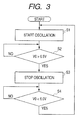
- Fig. 3 is a flowchart showing an example of the control state in the control section 23 provided to the power supply circuit according to the present embodiment.
- the control section 23 controls the square wave generator 30 to start oscillation in a constant duty cycle (step S1).
- the switching element 22 performs switching in sync with the oscillation output, thus increasing the output voltage in the output terminal 28.
- step S2 whether or not the output voltage V0 obtained in the output terminal 28 exceeds 6.5V is judged (step S2).
- the oscillation in the square wave generator 30 is continued, and the oscillation in the square wave generator 30 is stopped at the moment it exceeds 6.5V (step S3).
- step S4 judges whether or not the output voltage V0 has become lower than 6.0V. In the judgment, if the output voltage has become lower than 6.0V, the process returns to the step S1 to make the square wave generator 30 start oscillation at a constant duty cycle.
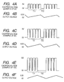
- Figs. 4A through 4F show the switching states in the switching element 22 of the power supply circuit according to the present embodiment separately for respective voltages of the input power.
- the case with the input voltage of 8V (Figs. 4A and 4B)
- the case with 9V (Figs. 4C and 4D)
- the case with 12V (Figs. 4E and 4F)
- the chopper voltages shown in Figs. 4A, 4C, and 4E are voltages at the point Vx in the circuit diagram shown in Fig. 1, which is an output before smoothing and after switching in the switching element 22.
- the duty cycle of the square wave output by the square wave generator 30 according to the present embodiment is set to 0.875 (the ratio of the periods in which the square wave is in the high level).
- the chopper voltage obtained by switching in the switching element 22 comes into the state shown in Fig. 4A.
- the output voltage shown in Fig. 4B gradually increases, and then a pause period T12 in which the chopper voltage becomes 0V occurs at the moment the output voltage exceeds 6.5V.
- the output voltage drops gradually from 6.5V to 6.0V because the output from the switching element 22 is not supplied thereto.
- 6.0V the square wave with a constant duty cycle is started again, thus the process of gradually increasing the output voltage as shown in Fig. 4B is repeated.
- the case with the 9V input will be explained.
- the chopper voltage obtained by switching in the switching element 22 comes into the state shown in Fig. 4C.
- the only difference between the state shown in Fig. 4C and the case with the 8V input shown in Fig. 4A is the pulse height of the voltage (the input voltage value), and the duty cycles are the same.
- the period T21 in which the chopper voltage of 9V is being output in the form of the square wave with a constant duty in the case with the 9V input becomes a shorter period than the period T11 in which the chopper voltage of 8V is being output, and the pause period T22 in Fig. 4C becomes longer than the pause period T12 in Fig. 4A.
- the period T31 in which the chopper voltage is being output becomes a shorter period than the period T21 in which the chopper voltage of 9V is being output, and the pause period T32 in Fig. 4E becomes longer than the pause period T22 shown in Fig. 4C. Therefore, in any cases of the input voltages, the output voltages shown in Figs. 4B, 4D, and 4F, move up and down between 6.5V and 6.0V at a constant cycle.
- the output voltage can be made be organized within a certain range. Since the switching power supply circuit thus controlled requires only a circuit for generating the square wave with a constant duty cycle as the circuit for generating the square wave, it is possible to cope with the variable input voltage with a simple and efficient circuit configuration. Therefore, it is suitable to the power supply circuit for supplying power to the circuits necessary to be always operated in the standby state.
- FIG. 5 and 6A through 6D the portions corresponding to Figs. 1 through 3, and 4A through 4F described in the first embodiment are denoted with the same reference numerals.
- the switching power supply circuit according to the present embodiment has the same basic configuration as the switching power supply circuit explained in the first embodiment, and controls switching of the input voltage with the square wave having the constant duty cycle, and performs the process for making the output voltage be organized within a certain range by setting the pause period in accordance with the voltage thereof. Further, in the present embodiment, a configuration for dealing with starting-up of the switching power supply circuit is adopted.
- Fig. 5 is a diagram showing the configuration of the switching power supply circuit according to the present embodiment.
- the input terminal 21 is connected to the switching element 22 via a resistor 29.
- the input terminal 21 is grounded via a capacitor 41.
- a coil 25 is connected between the switching element 22 and the output terminal 28, the connection point of the coil 25 and the output terminal 28 is grounded via the capacitor 26, and the connection point of the switching element 22 and the coil 25 is grounded via the flywheel diode 27.
- the coil 25 and the capacitor 26 form the smoothing circuit.
- the voltage obtained in the output terminal 28 is divided by the resistors 42, 43, and the obtained voltage is supplied to one of the comparing input terminals of the comparator 45 via a resistor 44.
- the other of the comparing input terminals of the comparator 45 is provided with the output voltage of a reference voltage source 46.
- the comparing output terminal and one of the comparing input terminals of the comparator 45 are connected with resistor 48.
- the signal output from the comparing output terminal of the comparator 45 is supplied to one of the input terminals of the AND gate (negative-true logic, hereinafter the same is applied thereto) 31 in the square wave generator 30.
- the signal output from the output terminal of the AND gate 31 is supplied to the gate of the switching element 22 via the inverter 32.
- the AND gate 31 and the inverter 32 in the square wave generator 30 are supplied with the power obtained in the input terminal 21, and the negative power supply terminals of the AND gate 31 and the inverter 32 are connected to the ground potential section via a resister 50. It should be noted that a capacitor 49 is connected between the input terminal 21 and the resistor 50.
- the output terminal of the inverter 32 in the square wave generator 30 is connected to the other of the input terminals of the AND gate 31 via a series circuit including a capacitor 33 and a resistor 37.
- the connection point of the output terminal of the AND gate 31 and the inverter 32 is connected to the connection point of the capacitor 33 and the resistor 37 via a series circuit of the resistor 34 and the diode 35.
- a resistor 36 is connected in parallel to the series circuit of the resistor 34 and the diode 35.
- the operation of the thus configured switching power supply circuit shown in Fig. 5 will be explained.
- the power obtained in the input terminal 21 is switched by the switching element 22 in sync with the square wave output by the square wave generator 30, smoothed by the smoothing circuit composed of the coil 25 and the capacitor 26, and output to the output terminal 28.
- This basic operation is the same as the operation of the configuration according to Fig. 1 explained in the first embodiment.
- the configuration of the comparator 45 and the peripheral circuit thereof is provided as a corresponding configuration to the control section 23 shown in Fig. 1.
- the voltage obtained in the output terminal 28 is divided by the resistors 42, 43, then compared with the output of the reference voltage source 46, and the comparison result output is supplied to the AND gate 31 in the square wave generator 30, thus the oscillation with a constant duty cycle in the square wave generator 30 can be controlled.
- the series circuit of the resistor 34 and the diode 35, and the resistor 36 form a time constant circuit together with the capacitor 33, and generate the square wave with a desired duty cycle.
- the oscillation operation of the square wave generator 30 is controlled, the oscillation with a constant duty cycle is on/off-controlled, the oscillation control is performed in the state explained in the first embodiment using Figs. 4A through 4F, and if the input voltage is in the stipulated range of, for example, 8V through 12V, the output voltage within the certain range of 6.0V through 6.5V can be output.
- Figs. 6A through 6D are charts showing an example of the state in which the square wave rises gradually at the beginning of the power input.
- Fig. 6A shows the power supply voltage (the input voltage) obtained in the input terminal 21, and the power supply voltage rapidly rises to a predetermined voltage (the voltage within the range of 8V through 12V) with the timing Ts.
- Fig. 6B shows the potential of the connection point Va of the negative power supply terminals of the AND gate 31 and the inverter 32 and the resistor 50, which is disposed between the negative power supply terminals of the AND gate 31 and the inverter 32 and the ground potential section.
- the potential of the connection point Va rises rapidly with the timing Ts because the capacitor 49 is connected thereto, and gradually drops to nearly 0V with a certain time constant.
- the output voltage waveform Vb (namely, the gate drive voltage for the switching element 22) of the square wave generator 30 becomes to have a shape in which the potential in the low level period of the square wave varies, as shown in Fig. 6C, in proportion to the potential Va shown in Fig. 6B.
- the gate drive voltage of the switching element 22 composed of P-channel FET rises gradually, and as a result, the output voltage Vc (the chopper voltage) of the switching element 22, as shown in Fig. 6D, becomes to have the shape in which the potential when the switching element 22 is in the on state rises gradually.
- Vc the chopper voltage
- the switching condition in the switching element 22 at the beginning of the power input becomes the preferable rising state, although it is the configuration for performing switching at a constant duty cycle, the rash current in the start-up state can be reduced, thus the elements in the power supply circuit can be protected.
- FIG. 7 and 8 the portions corresponding to Figs. 1 through 3, 4A through 4F, 5, and 6A through 6D described in the first and the second embodiment are denoted with the same reference numerals.
- the switching power supply circuit according to the present embodiment has a configuration of further switching into two stages the duty cycle of the square wave output by the square wave generator in accordance with the input power supply voltage in addition to the switching power supply circuit explained in the second embodiment, and other portions are assumed to be the same configuration as the switching power supply circuit shown in Fig. 5 described in the second embodiment.
- the power supply circuit according to the present embodiment shown in Fig. 7 is provided with a comparator 52 for comparing the voltage obtained in the input terminal 21 and the voltage of the reference voltage source 51.
- a comparator 52 for comparing the voltage obtained in the input terminal 21 and the voltage of the reference voltage source 51.
- the resisters 34, 36 (Fig. 5) in the square wave generator 30 two resisters 34a, 34b having different resistances from each other, and also two resistors 36a, 36b having different resistances from each other.
- the configuration for selecting either one of the resistors 34a, 34b by a switch 53 and for selecting either one of the resistors 36a, 36b by a switch 54 is adopted.
- the switches 53, 54 are configured to operate in conjunction with each other in accordance with the output of the comparator 52.
- the comparator 52 judges whether or not the input power supply voltage exceeds a specific voltage VTH, which is in a range of variation from 8V through 20V of the input power supply voltage.
- the switches 53, 54 are respectively connected to one of the resistors while the input voltage is equal to or lower than the specific voltage VTH, then the switches 53, 54 are respectively connected to the other of the resistors.
- the duty cycle of the square wave output by the square wave generator 30 can be controlled into two stages. Other portions are configured to be the same as the switching power supply circuit shown in Fig. 5.
- the flowchart shown in Fig. 8 shows the duty cycle setting condition.
- step S11 When the direct-current power supply is input to the input terminal 21 (step S11), whether or not the voltage of the input power supply exceeds the specific voltage VTH is judged (step S12), if it does not exceed, the oscillation state is fixed to oscillate with the first duty cycle (step S13). If it has exceeded, the oscillation state is fixed to oscillate with the second duty cycle (step S14).
- the duty cycle By thus switching the duty cycle into two stages, it becomes possible to make the switching condition in the switching element 22 constant, thus the operation sound caused by switching can be modified to have a frequency not so offensive to the ear. More specifically, if the duty cycle is made constant, as explained using Figs. 4A through 4F, the ratio between the switching period and the pause period varies, and in the condition in which a certain voltage is input, there is a possibility of causing a switching operation sound with a harsh frequency band (e.g., a frequency around 3000Hz). In such a case, by switching the duty cycle of the oscillation signal into two stages, the switching operation sound with a harsh frequency band can be prevented from being caused.
- a harsh frequency band e.g., a frequency around 3000Hz
Landscapes
- Engineering & Computer Science (AREA)
- Power Engineering (AREA)
- Physics & Mathematics (AREA)
- Electromagnetism (AREA)
- General Physics & Mathematics (AREA)
- Radar, Positioning & Navigation (AREA)
- Automation & Control Theory (AREA)
- Dc-Dc Converters (AREA)
Applications Claiming Priority (1)
| Application Number | Priority Date | Filing Date | Title |
|---|---|---|---|
| JP2006139461A JP2007312515A (ja) | 2006-05-18 | 2006-05-18 | スイッチング電源装置、電子機器及びスイッチング電源回路の制御方法 |
Publications (2)
| Publication Number | Publication Date |
|---|---|
| EP1858143A2 true EP1858143A2 (fr) | 2007-11-21 |
| EP1858143A3 EP1858143A3 (fr) | 2009-12-16 |
Family
ID=38476827
Family Applications (1)
| Application Number | Title | Priority Date | Filing Date |
|---|---|---|---|
| EP07108387A Withdrawn EP1858143A3 (fr) | 2006-05-18 | 2007-05-16 | Commutation d'alimentation électrique, appareil électronique, et procédé de commande de la commutation du circuit d'alimentation |
Country Status (6)
| Country | Link |
|---|---|
| US (1) | US20080007237A1 (fr) |
| EP (1) | EP1858143A3 (fr) |
| JP (1) | JP2007312515A (fr) |
| KR (1) | KR20070111995A (fr) |
| CN (1) | CN101075781A (fr) |
| TW (1) | TW200746601A (fr) |
Families Citing this family (243)
| Publication number | Priority date | Publication date | Assignee | Title |
|---|---|---|---|---|
| US9060770B2 (en) | 2003-05-20 | 2015-06-23 | Ethicon Endo-Surgery, Inc. | Robotically-driven surgical instrument with E-beam driver |
| US20070084897A1 (en) | 2003-05-20 | 2007-04-19 | Shelton Frederick E Iv | Articulating surgical stapling instrument incorporating a two-piece e-beam firing mechanism |
| US9072535B2 (en) | 2011-05-27 | 2015-07-07 | Ethicon Endo-Surgery, Inc. | Surgical stapling instruments with rotatable staple deployment arrangements |
| US11998198B2 (en) | 2004-07-28 | 2024-06-04 | Cilag Gmbh International | Surgical stapling instrument incorporating a two-piece E-beam firing mechanism |
| US11890012B2 (en) | 2004-07-28 | 2024-02-06 | Cilag Gmbh International | Staple cartridge comprising cartridge body and attached support |
| US11484312B2 (en) | 2005-08-31 | 2022-11-01 | Cilag Gmbh International | Staple cartridge comprising a staple driver arrangement |
| US7669746B2 (en) | 2005-08-31 | 2010-03-02 | Ethicon Endo-Surgery, Inc. | Staple cartridges for forming staples having differing formed staple heights |
| US7934630B2 (en) | 2005-08-31 | 2011-05-03 | Ethicon Endo-Surgery, Inc. | Staple cartridges for forming staples having differing formed staple heights |
| US10159482B2 (en) | 2005-08-31 | 2018-12-25 | Ethicon Llc | Fastener cartridge assembly comprising a fixed anvil and different staple heights |
| US11246590B2 (en) | 2005-08-31 | 2022-02-15 | Cilag Gmbh International | Staple cartridge including staple drivers having different unfired heights |
| US20070106317A1 (en) | 2005-11-09 | 2007-05-10 | Shelton Frederick E Iv | Hydraulically and electrically actuated articulation joints for surgical instruments |
| US8186555B2 (en) | 2006-01-31 | 2012-05-29 | Ethicon Endo-Surgery, Inc. | Motor-driven surgical cutting and fastening instrument with mechanical closure system |
| US8708213B2 (en) | 2006-01-31 | 2014-04-29 | Ethicon Endo-Surgery, Inc. | Surgical instrument having a feedback system |
| US20120292367A1 (en) | 2006-01-31 | 2012-11-22 | Ethicon Endo-Surgery, Inc. | Robotically-controlled end effector |
| US7845537B2 (en) | 2006-01-31 | 2010-12-07 | Ethicon Endo-Surgery, Inc. | Surgical instrument having recording capabilities |
| US11793518B2 (en) | 2006-01-31 | 2023-10-24 | Cilag Gmbh International | Powered surgical instruments with firing system lockout arrangements |
| US8820603B2 (en) | 2006-01-31 | 2014-09-02 | Ethicon Endo-Surgery, Inc. | Accessing data stored in a memory of a surgical instrument |
| US20110290856A1 (en) | 2006-01-31 | 2011-12-01 | Ethicon Endo-Surgery, Inc. | Robotically-controlled surgical instrument with force-feedback capabilities |
| US8992422B2 (en) | 2006-03-23 | 2015-03-31 | Ethicon Endo-Surgery, Inc. | Robotically-controlled endoscopic accessory channel |
| US10568652B2 (en) | 2006-09-29 | 2020-02-25 | Ethicon Llc | Surgical staples having attached drivers of different heights and stapling instruments for deploying the same |
| US11980366B2 (en) | 2006-10-03 | 2024-05-14 | Cilag Gmbh International | Surgical instrument |
| US8684253B2 (en) | 2007-01-10 | 2014-04-01 | Ethicon Endo-Surgery, Inc. | Surgical instrument with wireless communication between a control unit of a robotic system and remote sensor |
| US8632535B2 (en) | 2007-01-10 | 2014-01-21 | Ethicon Endo-Surgery, Inc. | Interlock and surgical instrument including same |
| US20080169332A1 (en) | 2007-01-11 | 2008-07-17 | Shelton Frederick E | Surgical stapling device with a curved cutting member |
| US8931682B2 (en) | 2007-06-04 | 2015-01-13 | Ethicon Endo-Surgery, Inc. | Robotically-controlled shaft based rotary drive systems for surgical instruments |
| US11857181B2 (en) | 2007-06-04 | 2024-01-02 | Cilag Gmbh International | Robotically-controlled shaft based rotary drive systems for surgical instruments |
| US7753245B2 (en) | 2007-06-22 | 2010-07-13 | Ethicon Endo-Surgery, Inc. | Surgical stapling instruments |
| US11849941B2 (en) | 2007-06-29 | 2023-12-26 | Cilag Gmbh International | Staple cartridge having staple cavities extending at a transverse angle relative to a longitudinal cartridge axis |
| US7508096B1 (en) | 2007-09-20 | 2009-03-24 | General Electric Company | Switching circuit apparatus having a series conduction path for servicing a load and switching method |
| KR20090065905A (ko) * | 2007-12-18 | 2009-06-23 | 삼성전자주식회사 | 영상처리장치, 영상처리시스템 및 영상처리장치의전원제어방법 |
| US7866527B2 (en) | 2008-02-14 | 2011-01-11 | Ethicon Endo-Surgery, Inc. | Surgical stapling apparatus with interlockable firing system |
| US8573465B2 (en) | 2008-02-14 | 2013-11-05 | Ethicon Endo-Surgery, Inc. | Robotically-controlled surgical end effector system with rotary actuated closure systems |
| US11986183B2 (en) | 2008-02-14 | 2024-05-21 | Cilag Gmbh International | Surgical cutting and fastening instrument comprising a plurality of sensors to measure an electrical parameter |
| US8636736B2 (en) | 2008-02-14 | 2014-01-28 | Ethicon Endo-Surgery, Inc. | Motorized surgical cutting and fastening instrument |
| RU2493788C2 (ru) | 2008-02-14 | 2013-09-27 | Этикон Эндо-Серджери, Инк. | Хирургический режущий и крепежный инструмент, имеющий радиочастотные электроды |
| US20130153641A1 (en) | 2008-02-15 | 2013-06-20 | Ethicon Endo-Surgery, Inc. | Releasable layer of material and surgical end effector having the same |
| US9386983B2 (en) | 2008-09-23 | 2016-07-12 | Ethicon Endo-Surgery, Llc | Robotically-controlled motorized surgical instrument |
| US8210411B2 (en) | 2008-09-23 | 2012-07-03 | Ethicon Endo-Surgery, Inc. | Motor-driven surgical cutting instrument |
| US11648005B2 (en) | 2008-09-23 | 2023-05-16 | Cilag Gmbh International | Robotically-controlled motorized surgical instrument with an end effector |
| US9005230B2 (en) | 2008-09-23 | 2015-04-14 | Ethicon Endo-Surgery, Inc. | Motorized surgical instrument |
| US8608045B2 (en) | 2008-10-10 | 2013-12-17 | Ethicon Endo-Sugery, Inc. | Powered surgical cutting and stapling apparatus with manually retractable firing system |
| US8220688B2 (en) | 2009-12-24 | 2012-07-17 | Ethicon Endo-Surgery, Inc. | Motor-driven surgical cutting instrument with electric actuator directional control assembly |
| US10405854B2 (en) | 2010-09-30 | 2019-09-10 | Ethicon Llc | Surgical stapling cartridge with layer retention features |
| US12213666B2 (en) | 2010-09-30 | 2025-02-04 | Cilag Gmbh International | Tissue thickness compensator comprising layers |
| US11812965B2 (en) | 2010-09-30 | 2023-11-14 | Cilag Gmbh International | Layer of material for a surgical end effector |
| US10945731B2 (en) | 2010-09-30 | 2021-03-16 | Ethicon Llc | Tissue thickness compensator comprising controlled release and expansion |
| US9320523B2 (en) | 2012-03-28 | 2016-04-26 | Ethicon Endo-Surgery, Llc | Tissue thickness compensator comprising tissue ingrowth features |
| US9629814B2 (en) | 2010-09-30 | 2017-04-25 | Ethicon Endo-Surgery, Llc | Tissue thickness compensator configured to redistribute compressive forces |
| US11925354B2 (en) | 2010-09-30 | 2024-03-12 | Cilag Gmbh International | Staple cartridge comprising staples positioned within a compressible portion thereof |
| US9113865B2 (en) | 2010-09-30 | 2015-08-25 | Ethicon Endo-Surgery, Inc. | Staple cartridge comprising a layer |
| US8695866B2 (en) | 2010-10-01 | 2014-04-15 | Ethicon Endo-Surgery, Inc. | Surgical instrument having a power control circuit |
| JP5771982B2 (ja) * | 2010-12-27 | 2015-09-02 | ミツミ電機株式会社 | スイッチング電源装置 |
| BR112013027794B1 (pt) | 2011-04-29 | 2020-12-15 | Ethicon Endo-Surgery, Inc | Conjunto de cartucho de grampos |
| US11207064B2 (en) | 2011-05-27 | 2021-12-28 | Cilag Gmbh International | Automated end effector component reloading system for use with a robotic system |
| MX350846B (es) | 2012-03-28 | 2017-09-22 | Ethicon Endo Surgery Inc | Compensador de grosor de tejido que comprende cápsulas que definen un ambiente de baja presión. |
| MX358135B (es) | 2012-03-28 | 2018-08-06 | Ethicon Endo Surgery Inc | Compensador de grosor de tejido que comprende una pluralidad de capas. |
| US9101358B2 (en) | 2012-06-15 | 2015-08-11 | Ethicon Endo-Surgery, Inc. | Articulatable surgical instrument comprising a firing drive |
| US9282974B2 (en) | 2012-06-28 | 2016-03-15 | Ethicon Endo-Surgery, Llc | Empty clip cartridge lockout |
| US12383267B2 (en) | 2012-06-28 | 2025-08-12 | Cilag Gmbh International | Robotically powered surgical device with manually-actuatable reversing system |
| US9289256B2 (en) | 2012-06-28 | 2016-03-22 | Ethicon Endo-Surgery, Llc | Surgical end effectors having angled tissue-contacting surfaces |
| US20140001231A1 (en) | 2012-06-28 | 2014-01-02 | Ethicon Endo-Surgery, Inc. | Firing system lockout arrangements for surgical instruments |
| US9226751B2 (en) | 2012-06-28 | 2016-01-05 | Ethicon Endo-Surgery, Inc. | Surgical instrument system including replaceable end effectors |
| KR101394018B1 (ko) * | 2012-09-12 | 2014-05-12 | 엘지이노텍 주식회사 | 전력 공급 장치 및 무선전력 송신장치 |
| RU2669463C2 (ru) | 2013-03-01 | 2018-10-11 | Этикон Эндо-Серджери, Инк. | Хирургический инструмент с мягким упором |
| MX368026B (es) | 2013-03-01 | 2019-09-12 | Ethicon Endo Surgery Inc | Instrumento quirúrgico articulable con vías conductoras para la comunicación de la señal. |
| US9629629B2 (en) | 2013-03-14 | 2017-04-25 | Ethicon Endo-Surgey, LLC | Control systems for surgical instruments |
| BR112015026109B1 (pt) | 2013-04-16 | 2022-02-22 | Ethicon Endo-Surgery, Inc | Instrumento cirúrgico |
| US20150053737A1 (en) | 2013-08-23 | 2015-02-26 | Ethicon Endo-Surgery, Inc. | End effector detection systems for surgical instruments |
| BR112016021943B1 (pt) | 2014-03-26 | 2022-06-14 | Ethicon Endo-Surgery, Llc | Instrumento cirúrgico para uso por um operador em um procedimento cirúrgico |
| US12232723B2 (en) | 2014-03-26 | 2025-02-25 | Cilag Gmbh International | Systems and methods for controlling a segmented circuit |
| US9750499B2 (en) | 2014-03-26 | 2017-09-05 | Ethicon Llc | Surgical stapling instrument system |
| US10013049B2 (en) | 2014-03-26 | 2018-07-03 | Ethicon Llc | Power management through sleep options of segmented circuit and wake up control |
| US10327764B2 (en) | 2014-09-26 | 2019-06-25 | Ethicon Llc | Method for creating a flexible staple line |
| CN106456158B (zh) | 2014-04-16 | 2019-02-05 | 伊西康内外科有限责任公司 | 包括非一致紧固件的紧固件仓 |
| US20150297223A1 (en) | 2014-04-16 | 2015-10-22 | Ethicon Endo-Surgery, Inc. | Fastener cartridges including extensions having different configurations |
| CN106456176B (zh) | 2014-04-16 | 2019-06-28 | 伊西康内外科有限责任公司 | 包括具有不同构型的延伸部的紧固件仓 |
| JP6532889B2 (ja) | 2014-04-16 | 2019-06-19 | エシコン エルエルシーEthicon LLC | 締結具カートリッジ組立体及びステープル保持具カバー配置構成 |
| BR112017004361B1 (pt) | 2014-09-05 | 2023-04-11 | Ethicon Llc | Sistema eletrônico para um instrumento cirúrgico |
| US9724094B2 (en) | 2014-09-05 | 2017-08-08 | Ethicon Llc | Adjunct with integrated sensors to quantify tissue compression |
| US11311294B2 (en) | 2014-09-05 | 2022-04-26 | Cilag Gmbh International | Powered medical device including measurement of closure state of jaws |
| US10105142B2 (en) | 2014-09-18 | 2018-10-23 | Ethicon Llc | Surgical stapler with plurality of cutting elements |
| US11523821B2 (en) | 2014-09-26 | 2022-12-13 | Cilag Gmbh International | Method for creating a flexible staple line |
| US9924944B2 (en) | 2014-10-16 | 2018-03-27 | Ethicon Llc | Staple cartridge comprising an adjunct material |
| US11141153B2 (en) | 2014-10-29 | 2021-10-12 | Cilag Gmbh International | Staple cartridges comprising driver arrangements |
| US10517594B2 (en) | 2014-10-29 | 2019-12-31 | Ethicon Llc | Cartridge assemblies for surgical staplers |
| US10736636B2 (en) | 2014-12-10 | 2020-08-11 | Ethicon Llc | Articulatable surgical instrument system |
| US9987000B2 (en) | 2014-12-18 | 2018-06-05 | Ethicon Llc | Surgical instrument assembly comprising a flexible articulation system |
| US10245027B2 (en) | 2014-12-18 | 2019-04-02 | Ethicon Llc | Surgical instrument with an anvil that is selectively movable about a discrete non-movable axis relative to a staple cartridge |
| RU2703684C2 (ru) | 2014-12-18 | 2019-10-21 | ЭТИКОН ЭНДО-СЕРДЖЕРИ, ЭлЭлСи | Хирургический инструмент с упором, который выполнен с возможностью избирательного перемещения относительно кассеты со скобами вокруг дискретной неподвижной оси |
| US10085748B2 (en) | 2014-12-18 | 2018-10-02 | Ethicon Llc | Locking arrangements for detachable shaft assemblies with articulatable surgical end effectors |
| US11154301B2 (en) | 2015-02-27 | 2021-10-26 | Cilag Gmbh International | Modular stapling assembly |
| US9808246B2 (en) | 2015-03-06 | 2017-11-07 | Ethicon Endo-Surgery, Llc | Method of operating a powered surgical instrument |
| US10441279B2 (en) | 2015-03-06 | 2019-10-15 | Ethicon Llc | Multiple level thresholds to modify operation of powered surgical instruments |
| JP2020121162A (ja) | 2015-03-06 | 2020-08-13 | エシコン エルエルシーEthicon LLC | 測定の安定性要素、クリープ要素、及び粘弾性要素を決定するためのセンサデータの時間依存性評価 |
| US10390825B2 (en) | 2015-03-31 | 2019-08-27 | Ethicon Llc | Surgical instrument with progressive rotary drive systems |
| US10105139B2 (en) | 2015-09-23 | 2018-10-23 | Ethicon Llc | Surgical stapler having downstream current-based motor control |
| US10238386B2 (en) | 2015-09-23 | 2019-03-26 | Ethicon Llc | Surgical stapler having motor control based on an electrical parameter related to a motor current |
| US10299878B2 (en) | 2015-09-25 | 2019-05-28 | Ethicon Llc | Implantable adjunct systems for determining adjunct skew |
| US11890015B2 (en) | 2015-09-30 | 2024-02-06 | Cilag Gmbh International | Compressible adjunct with crossing spacer fibers |
| US10736633B2 (en) | 2015-09-30 | 2020-08-11 | Ethicon Llc | Compressible adjunct with looping members |
| US10172620B2 (en) | 2015-09-30 | 2019-01-08 | Ethicon Llc | Compressible adjuncts with bonding nodes |
| US10292704B2 (en) | 2015-12-30 | 2019-05-21 | Ethicon Llc | Mechanisms for compensating for battery pack failure in powered surgical instruments |
| US10265068B2 (en) | 2015-12-30 | 2019-04-23 | Ethicon Llc | Surgical instruments with separable motors and motor control circuits |
| BR112018016098B1 (pt) | 2016-02-09 | 2023-02-23 | Ethicon Llc | Instrumento cirúrgico |
| US11213293B2 (en) | 2016-02-09 | 2022-01-04 | Cilag Gmbh International | Articulatable surgical instruments with single articulation link arrangements |
| US10448948B2 (en) | 2016-02-12 | 2019-10-22 | Ethicon Llc | Mechanisms for compensating for drivetrain failure in powered surgical instruments |
| US10357247B2 (en) | 2016-04-15 | 2019-07-23 | Ethicon Llc | Surgical instrument with multiple program responses during a firing motion |
| US11607239B2 (en) | 2016-04-15 | 2023-03-21 | Cilag Gmbh International | Systems and methods for controlling a surgical stapling and cutting instrument |
| US10828028B2 (en) | 2016-04-15 | 2020-11-10 | Ethicon Llc | Surgical instrument with multiple program responses during a firing motion |
| US10426467B2 (en) | 2016-04-15 | 2019-10-01 | Ethicon Llc | Surgical instrument with detection sensors |
| US20170296173A1 (en) | 2016-04-18 | 2017-10-19 | Ethicon Endo-Surgery, Llc | Method for operating a surgical instrument |
| US10433840B2 (en) | 2016-04-18 | 2019-10-08 | Ethicon Llc | Surgical instrument comprising a replaceable cartridge jaw |
| US10500000B2 (en) | 2016-08-16 | 2019-12-10 | Ethicon Llc | Surgical tool with manual control of end effector jaws |
| US10639035B2 (en) | 2016-12-21 | 2020-05-05 | Ethicon Llc | Surgical stapling instruments and replaceable tool assemblies thereof |
| US20180168623A1 (en) | 2016-12-21 | 2018-06-21 | Ethicon Endo-Surgery, Llc | Surgical stapling systems |
| JP7010957B2 (ja) | 2016-12-21 | 2022-01-26 | エシコン エルエルシー | ロックアウトを備えるシャフトアセンブリ |
| US10758230B2 (en) | 2016-12-21 | 2020-09-01 | Ethicon Llc | Surgical instrument with primary and safety processors |
| US10568626B2 (en) | 2016-12-21 | 2020-02-25 | Ethicon Llc | Surgical instruments with jaw opening features for increasing a jaw opening distance |
| US11090048B2 (en) | 2016-12-21 | 2021-08-17 | Cilag Gmbh International | Method for resetting a fuse of a surgical instrument shaft |
| JP2020501815A (ja) | 2016-12-21 | 2020-01-23 | エシコン エルエルシーEthicon LLC | 外科用ステープル留めシステム |
| CN110114014B (zh) | 2016-12-21 | 2022-08-09 | 爱惜康有限责任公司 | 包括端部执行器闭锁件和击发组件闭锁件的外科器械系统 |
| US10918385B2 (en) | 2016-12-21 | 2021-02-16 | Ethicon Llc | Surgical system comprising a firing member rotatable into an articulation state to articulate an end effector of the surgical system |
| US20180168615A1 (en) | 2016-12-21 | 2018-06-21 | Ethicon Endo-Surgery, Llc | Method of deforming staples from two different types of staple cartridges with the same surgical stapling instrument |
| JP7010956B2 (ja) | 2016-12-21 | 2022-01-26 | エシコン エルエルシー | 組織をステープル留めする方法 |
| US10307170B2 (en) | 2017-06-20 | 2019-06-04 | Ethicon Llc | Method for closed loop control of motor velocity of a surgical stapling and cutting instrument |
| US10881399B2 (en) | 2017-06-20 | 2021-01-05 | Ethicon Llc | Techniques for adaptive control of motor velocity of a surgical stapling and cutting instrument |
| US11517325B2 (en) | 2017-06-20 | 2022-12-06 | Cilag Gmbh International | Closed loop feedback control of motor velocity of a surgical stapling and cutting instrument based on measured displacement distance traveled over a specified time interval |
| US11653914B2 (en) | 2017-06-20 | 2023-05-23 | Cilag Gmbh International | Systems and methods for controlling motor velocity of a surgical stapling and cutting instrument according to articulation angle of end effector |
| US10779820B2 (en) | 2017-06-20 | 2020-09-22 | Ethicon Llc | Systems and methods for controlling motor speed according to user input for a surgical instrument |
| US11266405B2 (en) | 2017-06-27 | 2022-03-08 | Cilag Gmbh International | Surgical anvil manufacturing methods |
| US10993716B2 (en) | 2017-06-27 | 2021-05-04 | Ethicon Llc | Surgical anvil arrangements |
| US11564686B2 (en) | 2017-06-28 | 2023-01-31 | Cilag Gmbh International | Surgical shaft assemblies with flexible interfaces |
| US11000279B2 (en) | 2017-06-28 | 2021-05-11 | Ethicon Llc | Surgical instrument comprising an articulation system ratio |
| USD906355S1 (en) | 2017-06-28 | 2020-12-29 | Ethicon Llc | Display screen or portion thereof with a graphical user interface for a surgical instrument |
| BR112019027065B1 (pt) | 2017-06-28 | 2023-12-26 | Ethicon Llc | Instrumento cirúrgico e sistema cirúrgico |
| EP4070740B1 (fr) | 2017-06-28 | 2025-03-26 | Cilag GmbH International | Instrument chirurgical comprenant des coupleurs rotatifs actionnables de façon sélective |
| US20190000461A1 (en) | 2017-06-28 | 2019-01-03 | Ethicon Llc | Surgical cutting and fastening devices with pivotable anvil with a tissue locating arrangement in close proximity to an anvil pivot axis |
| US10765427B2 (en) | 2017-06-28 | 2020-09-08 | Ethicon Llc | Method for articulating a surgical instrument |
| US10932772B2 (en) | 2017-06-29 | 2021-03-02 | Ethicon Llc | Methods for closed loop velocity control for robotic surgical instrument |
| US11974742B2 (en) | 2017-08-03 | 2024-05-07 | Cilag Gmbh International | Surgical system comprising an articulation bailout |
| US11944300B2 (en) | 2017-08-03 | 2024-04-02 | Cilag Gmbh International | Method for operating a surgical system bailout |
| US11134944B2 (en) | 2017-10-30 | 2021-10-05 | Cilag Gmbh International | Surgical stapler knife motion controls |
| US10842490B2 (en) | 2017-10-31 | 2020-11-24 | Ethicon Llc | Cartridge body design with force reduction based on firing completion |
| US10779826B2 (en) | 2017-12-15 | 2020-09-22 | Ethicon Llc | Methods of operating surgical end effectors |
| US10835330B2 (en) | 2017-12-19 | 2020-11-17 | Ethicon Llc | Method for determining the position of a rotatable jaw of a surgical instrument attachment assembly |
| US11751867B2 (en) | 2017-12-21 | 2023-09-12 | Cilag Gmbh International | Surgical instrument comprising sequenced systems |
| US12336705B2 (en) | 2017-12-21 | 2025-06-24 | Cilag Gmbh International | Continuous use self-propelled stapling instrument |
| JP7022001B2 (ja) * | 2018-04-11 | 2022-02-17 | ローム株式会社 | スイッチング制御回路 |
| JP6842092B2 (ja) * | 2018-05-31 | 2021-03-17 | 国立大学法人 東京大学 | 電源回路、および振動発電装置 |
| US11291440B2 (en) | 2018-08-20 | 2022-04-05 | Cilag Gmbh International | Method for operating a powered articulatable surgical instrument |
| US20200054321A1 (en) | 2018-08-20 | 2020-02-20 | Ethicon Llc | Surgical instruments with progressive jaw closure arrangements |
| US11207065B2 (en) | 2018-08-20 | 2021-12-28 | Cilag Gmbh International | Method for fabricating surgical stapler anvils |
| US11696761B2 (en) | 2019-03-25 | 2023-07-11 | Cilag Gmbh International | Firing drive arrangements for surgical systems |
| CN109951076B (zh) * | 2019-04-11 | 2020-05-12 | 成都盛芯微科技有限公司 | 一种降低系统睡眠功耗的开关电源自适应占空比调节方法 |
| US11648009B2 (en) | 2019-04-30 | 2023-05-16 | Cilag Gmbh International | Rotatable jaw tip for a surgical instrument |
| US20200345359A1 (en) | 2019-04-30 | 2020-11-05 | Ethicon Llc | Tissue stop for a surgical instrument |
| US11903581B2 (en) | 2019-04-30 | 2024-02-20 | Cilag Gmbh International | Methods for stapling tissue using a surgical instrument |
| US12004740B2 (en) | 2019-06-28 | 2024-06-11 | Cilag Gmbh International | Surgical stapling system having an information decryption protocol |
| US11553971B2 (en) | 2019-06-28 | 2023-01-17 | Cilag Gmbh International | Surgical RFID assemblies for display and communication |
| US11627959B2 (en) | 2019-06-28 | 2023-04-18 | Cilag Gmbh International | Surgical instruments including manual and powered system lockouts |
| US11684434B2 (en) | 2019-06-28 | 2023-06-27 | Cilag Gmbh International | Surgical RFID assemblies for instrument operational setting control |
| US11660163B2 (en) | 2019-06-28 | 2023-05-30 | Cilag Gmbh International | Surgical system with RFID tags for updating motor assembly parameters |
| US11241235B2 (en) | 2019-06-28 | 2022-02-08 | Cilag Gmbh International | Method of using multiple RFID chips with a surgical assembly |
| US11771419B2 (en) | 2019-06-28 | 2023-10-03 | Cilag Gmbh International | Packaging for a replaceable component of a surgical stapling system |
| US11638587B2 (en) | 2019-06-28 | 2023-05-02 | Cilag Gmbh International | RFID identification systems for surgical instruments |
| US11523822B2 (en) | 2019-06-28 | 2022-12-13 | Cilag Gmbh International | Battery pack including a circuit interrupter |
| US11576672B2 (en) | 2019-12-19 | 2023-02-14 | Cilag Gmbh International | Surgical instrument comprising a closure system including a closure member and an opening member driven by a drive screw |
| US12035913B2 (en) | 2019-12-19 | 2024-07-16 | Cilag Gmbh International | Staple cartridge comprising a deployable knife |
| US11607219B2 (en) | 2019-12-19 | 2023-03-21 | Cilag Gmbh International | Staple cartridge comprising a detachable tissue cutting knife |
| US11844520B2 (en) | 2019-12-19 | 2023-12-19 | Cilag Gmbh International | Staple cartridge comprising driver retention members |
| US11504122B2 (en) | 2019-12-19 | 2022-11-22 | Cilag Gmbh International | Surgical instrument comprising a nested firing member |
| US11529139B2 (en) | 2019-12-19 | 2022-12-20 | Cilag Gmbh International | Motor driven surgical instrument |
| US11559304B2 (en) | 2019-12-19 | 2023-01-24 | Cilag Gmbh International | Surgical instrument comprising a rapid closure mechanism |
| US11911032B2 (en) | 2019-12-19 | 2024-02-27 | Cilag Gmbh International | Staple cartridge comprising a seating cam |
| US11529137B2 (en) | 2019-12-19 | 2022-12-20 | Cilag Gmbh International | Staple cartridge comprising driver retention members |
| US11701111B2 (en) | 2019-12-19 | 2023-07-18 | Cilag Gmbh International | Method for operating a surgical stapling instrument |
| USD975851S1 (en) | 2020-06-02 | 2023-01-17 | Cilag Gmbh International | Staple cartridge |
| USD975850S1 (en) | 2020-06-02 | 2023-01-17 | Cilag Gmbh International | Staple cartridge |
| USD974560S1 (en) | 2020-06-02 | 2023-01-03 | Cilag Gmbh International | Staple cartridge |
| USD976401S1 (en) | 2020-06-02 | 2023-01-24 | Cilag Gmbh International | Staple cartridge |
| US11638582B2 (en) | 2020-07-28 | 2023-05-02 | Cilag Gmbh International | Surgical instruments with torsion spine drive arrangements |
| US11779330B2 (en) | 2020-10-29 | 2023-10-10 | Cilag Gmbh International | Surgical instrument comprising a jaw alignment system |
| USD980425S1 (en) | 2020-10-29 | 2023-03-07 | Cilag Gmbh International | Surgical instrument assembly |
| USD1013170S1 (en) | 2020-10-29 | 2024-01-30 | Cilag Gmbh International | Surgical instrument assembly |
| US12053175B2 (en) | 2020-10-29 | 2024-08-06 | Cilag Gmbh International | Surgical instrument comprising a stowed closure actuator stop |
| US11534259B2 (en) | 2020-10-29 | 2022-12-27 | Cilag Gmbh International | Surgical instrument comprising an articulation indicator |
| US11931025B2 (en) | 2020-10-29 | 2024-03-19 | Cilag Gmbh International | Surgical instrument comprising a releasable closure drive lock |
| US11896217B2 (en) | 2020-10-29 | 2024-02-13 | Cilag Gmbh International | Surgical instrument comprising an articulation lock |
| US11452526B2 (en) | 2020-10-29 | 2022-09-27 | Cilag Gmbh International | Surgical instrument comprising a staged voltage regulation start-up system |
| US11517390B2 (en) | 2020-10-29 | 2022-12-06 | Cilag Gmbh International | Surgical instrument comprising a limited travel switch |
| US11717289B2 (en) | 2020-10-29 | 2023-08-08 | Cilag Gmbh International | Surgical instrument comprising an indicator which indicates that an articulation drive is actuatable |
| US11617577B2 (en) | 2020-10-29 | 2023-04-04 | Cilag Gmbh International | Surgical instrument comprising a sensor configured to sense whether an articulation drive of the surgical instrument is actuatable |
| US11844518B2 (en) | 2020-10-29 | 2023-12-19 | Cilag Gmbh International | Method for operating a surgical instrument |
| US11944296B2 (en) | 2020-12-02 | 2024-04-02 | Cilag Gmbh International | Powered surgical instruments with external connectors |
| US11653915B2 (en) | 2020-12-02 | 2023-05-23 | Cilag Gmbh International | Surgical instruments with sled location detection and adjustment features |
| US11890010B2 (en) | 2020-12-02 | 2024-02-06 | Cllag GmbH International | Dual-sided reinforced reload for surgical instruments |
| US11678882B2 (en) | 2020-12-02 | 2023-06-20 | Cilag Gmbh International | Surgical instruments with interactive features to remedy incidental sled movements |
| US11737751B2 (en) | 2020-12-02 | 2023-08-29 | Cilag Gmbh International | Devices and methods of managing energy dissipated within sterile barriers of surgical instrument housings |
| US11653920B2 (en) | 2020-12-02 | 2023-05-23 | Cilag Gmbh International | Powered surgical instruments with communication interfaces through sterile barrier |
| US12471982B2 (en) | 2020-12-02 | 2025-11-18 | Cilag Gmbh International | Method for tissue treatment by surgical instrument |
| US11627960B2 (en) | 2020-12-02 | 2023-04-18 | Cilag Gmbh International | Powered surgical instruments with smart reload with separately attachable exteriorly mounted wiring connections |
| US11849943B2 (en) | 2020-12-02 | 2023-12-26 | Cilag Gmbh International | Surgical instrument with cartridge release mechanisms |
| US11744581B2 (en) | 2020-12-02 | 2023-09-05 | Cilag Gmbh International | Powered surgical instruments with multi-phase tissue treatment |
| US11723657B2 (en) | 2021-02-26 | 2023-08-15 | Cilag Gmbh International | Adjustable communication based on available bandwidth and power capacity |
| US11950779B2 (en) | 2021-02-26 | 2024-04-09 | Cilag Gmbh International | Method of powering and communicating with a staple cartridge |
| US11749877B2 (en) | 2021-02-26 | 2023-09-05 | Cilag Gmbh International | Stapling instrument comprising a signal antenna |
| US11950777B2 (en) | 2021-02-26 | 2024-04-09 | Cilag Gmbh International | Staple cartridge comprising an information access control system |
| US11744583B2 (en) | 2021-02-26 | 2023-09-05 | Cilag Gmbh International | Distal communication array to tune frequency of RF systems |
| US11730473B2 (en) | 2021-02-26 | 2023-08-22 | Cilag Gmbh International | Monitoring of manufacturing life-cycle |
| US11751869B2 (en) | 2021-02-26 | 2023-09-12 | Cilag Gmbh International | Monitoring of multiple sensors over time to detect moving characteristics of tissue |
| US11812964B2 (en) | 2021-02-26 | 2023-11-14 | Cilag Gmbh International | Staple cartridge comprising a power management circuit |
| US12108951B2 (en) | 2021-02-26 | 2024-10-08 | Cilag Gmbh International | Staple cartridge comprising a sensing array and a temperature control system |
| US11925349B2 (en) | 2021-02-26 | 2024-03-12 | Cilag Gmbh International | Adjustment to transfer parameters to improve available power |
| US11793514B2 (en) | 2021-02-26 | 2023-10-24 | Cilag Gmbh International | Staple cartridge comprising sensor array which may be embedded in cartridge body |
| US11701113B2 (en) | 2021-02-26 | 2023-07-18 | Cilag Gmbh International | Stapling instrument comprising a separate power antenna and a data transfer antenna |
| US11980362B2 (en) | 2021-02-26 | 2024-05-14 | Cilag Gmbh International | Surgical instrument system comprising a power transfer coil |
| US11696757B2 (en) | 2021-02-26 | 2023-07-11 | Cilag Gmbh International | Monitoring of internal systems to detect and track cartridge motion status |
| US12324580B2 (en) | 2021-02-26 | 2025-06-10 | Cilag Gmbh International | Method of powering and communicating with a staple cartridge |
| US11806011B2 (en) | 2021-03-22 | 2023-11-07 | Cilag Gmbh International | Stapling instrument comprising tissue compression systems |
| US11759202B2 (en) | 2021-03-22 | 2023-09-19 | Cilag Gmbh International | Staple cartridge comprising an implantable layer |
| US11717291B2 (en) | 2021-03-22 | 2023-08-08 | Cilag Gmbh International | Staple cartridge comprising staples configured to apply different tissue compression |
| US11723658B2 (en) | 2021-03-22 | 2023-08-15 | Cilag Gmbh International | Staple cartridge comprising a firing lockout |
| US11737749B2 (en) | 2021-03-22 | 2023-08-29 | Cilag Gmbh International | Surgical stapling instrument comprising a retraction system |
| US11826012B2 (en) | 2021-03-22 | 2023-11-28 | Cilag Gmbh International | Stapling instrument comprising a pulsed motor-driven firing rack |
| US11826042B2 (en) | 2021-03-22 | 2023-11-28 | Cilag Gmbh International | Surgical instrument comprising a firing drive including a selectable leverage mechanism |
| US11944336B2 (en) | 2021-03-24 | 2024-04-02 | Cilag Gmbh International | Joint arrangements for multi-planar alignment and support of operational drive shafts in articulatable surgical instruments |
| US12102323B2 (en) | 2021-03-24 | 2024-10-01 | Cilag Gmbh International | Rotary-driven surgical stapling assembly comprising a floatable component |
| US11786239B2 (en) | 2021-03-24 | 2023-10-17 | Cilag Gmbh International | Surgical instrument articulation joint arrangements comprising multiple moving linkage features |
| US11793516B2 (en) | 2021-03-24 | 2023-10-24 | Cilag Gmbh International | Surgical staple cartridge comprising longitudinal support beam |
| US11849944B2 (en) | 2021-03-24 | 2023-12-26 | Cilag Gmbh International | Drivers for fastener cartridge assemblies having rotary drive screws |
| US11744603B2 (en) | 2021-03-24 | 2023-09-05 | Cilag Gmbh International | Multi-axis pivot joints for surgical instruments and methods for manufacturing same |
| US11857183B2 (en) | 2021-03-24 | 2024-01-02 | Cilag Gmbh International | Stapling assembly components having metal substrates and plastic bodies |
| US11903582B2 (en) | 2021-03-24 | 2024-02-20 | Cilag Gmbh International | Leveraging surfaces for cartridge installation |
| US11849945B2 (en) | 2021-03-24 | 2023-12-26 | Cilag Gmbh International | Rotary-driven surgical stapling assembly comprising eccentrically driven firing member |
| US11896219B2 (en) | 2021-03-24 | 2024-02-13 | Cilag Gmbh International | Mating features between drivers and underside of a cartridge deck |
| US11896218B2 (en) | 2021-03-24 | 2024-02-13 | Cilag Gmbh International | Method of using a powered stapling device |
| US11832816B2 (en) | 2021-03-24 | 2023-12-05 | Cilag Gmbh International | Surgical stapling assembly comprising nonplanar staples and planar staples |
| US11786243B2 (en) | 2021-03-24 | 2023-10-17 | Cilag Gmbh International | Firing members having flexible portions for adapting to a load during a surgical firing stroke |
| US20220378425A1 (en) | 2021-05-28 | 2022-12-01 | Cilag Gmbh International | Stapling instrument comprising a control system that controls a firing stroke length |
| US11980363B2 (en) | 2021-10-18 | 2024-05-14 | Cilag Gmbh International | Row-to-row staple array variations |
| US12432790B2 (en) | 2021-10-28 | 2025-09-30 | Cilag Gmbh International | Method and device for transmitting UART communications over a security short range wireless communication |
| US12089841B2 (en) | 2021-10-28 | 2024-09-17 | Cilag CmbH International | Staple cartridge identification systems |
| US11937816B2 (en) | 2021-10-28 | 2024-03-26 | Cilag Gmbh International | Electrical lead arrangements for surgical instruments |
Family Cites Families (13)
| Publication number | Priority date | Publication date | Assignee | Title |
|---|---|---|---|---|
| JP3100914B2 (ja) * | 1996-12-25 | 2000-10-23 | 松下電器産業株式会社 | スイッチング電源 |
| TW357944U (en) * | 1997-03-24 | 1999-05-01 | Advance Reality Technology Inc | Wave width controller |
| JP2000069746A (ja) * | 1998-08-21 | 2000-03-03 | Fujitsu Ltd | Dc−dcコンバータの制御方法、dc−dcコンバータの制御回路、及び、dc−dcコンバータ |
| US6040686A (en) * | 1999-01-07 | 2000-03-21 | Linear Technology Corporation | Low noise step-down switching regulator circuits with programmable slew rate limiter and methods of use |
| JP2000217340A (ja) * | 1999-01-21 | 2000-08-04 | Fujitsu Ltd | 最大デュ―ティ比の矩形波信号生成方法、デュ―ティ比設定回路及びdc―dcコンバ―タ |
| JP3300683B2 (ja) * | 1999-04-15 | 2002-07-08 | 松下電器産業株式会社 | スイッチング電源 |
| US6316926B1 (en) * | 2000-05-19 | 2001-11-13 | Stmicroelectronics S.R.L. | Switching control circuit |
| US6275018B1 (en) * | 2000-06-02 | 2001-08-14 | Iwatt | Switching power converter with gated oscillator controller |
| US6531853B2 (en) * | 2000-11-21 | 2003-03-11 | Rohm Co., Ltd. | DC-DC converter |
| JP3963257B2 (ja) * | 2002-02-14 | 2007-08-22 | 富士通株式会社 | Dc−dcコンバータ、電子機器、デューティ比設定回路 |
| US6812782B2 (en) * | 2002-10-25 | 2004-11-02 | Texas Instruments Incorporated | Switch mode converter that allows 100% duty cycle on gate driver |
| ITMI20031315A1 (it) * | 2003-06-27 | 2004-12-28 | St Microelectronics Srl | Dispositivo per la correzione del fattore di potenza in alimentatori a commutazione forzata. |
| CN1688091A (zh) * | 2005-04-29 | 2005-10-26 | 中国科学院上海光学精密机械研究所 | 小型电感升压式直流变换器 |
-
2006
- 2006-05-18 JP JP2006139461A patent/JP2007312515A/ja active Pending
-
2007
- 2007-04-25 TW TW096114638A patent/TW200746601A/zh unknown
- 2007-05-14 KR KR1020070046451A patent/KR20070111995A/ko not_active Withdrawn
- 2007-05-16 EP EP07108387A patent/EP1858143A3/fr not_active Withdrawn
- 2007-05-16 US US11/803,937 patent/US20080007237A1/en not_active Abandoned
- 2007-05-18 CN CNA2007101051157A patent/CN101075781A/zh active Pending
Also Published As
| Publication number | Publication date |
|---|---|
| EP1858143A3 (fr) | 2009-12-16 |
| US20080007237A1 (en) | 2008-01-10 |
| TW200746601A (en) | 2007-12-16 |
| KR20070111995A (ko) | 2007-11-22 |
| JP2007312515A (ja) | 2007-11-29 |
| CN101075781A (zh) | 2007-11-21 |
Similar Documents
| Publication | Publication Date | Title |
|---|---|---|
| EP1858143A2 (fr) | Commutation d'alimentation électrique, appareil électronique, et procédé de commande de la commutation du circuit d'alimentation | |
| KR100944668B1 (ko) | 전력 공급 장치 및 그 동작 제어 방법 | |
| JP5116732B2 (ja) | 電源制御装置、電源システムおよび電子機器 | |
| JP5330962B2 (ja) | Dc−dcコンバータ | |
| JP4687958B2 (ja) | Dc−dcコンバータ | |
| KR100386246B1 (ko) | 저소비전력 대기 전원회로 | |
| EP2083497A3 (fr) | Système de commande électronique et unité d'alimentation du système | |
| US20100301824A1 (en) | Step-up dc/dc switching converter and semiconductor integrated circuit device | |
| JP2008236919A (ja) | スイッチング電源装置の制御回路及び制御方法 | |
| JP2011182482A (ja) | スイッチング昇圧型dc−dcコンバータおよび半導体集積回路装置 | |
| EP2431965B1 (fr) | Appareil d'affichage et dispositifs de circuit de puissance correspondants | |
| KR20170006697A (ko) | 전기 차량용 충전 장치 및 이를 이용한 부하의 전원 공급방법 | |
| US20120008343A1 (en) | High-Voltage Startup Method and Power Management Apparatus | |
| EP1715568A2 (fr) | Circuit de tension constante capable de réduire le temps requiert pour démarrage, appareil semi-conducteur incluant ce circuit et méthode de control de ce circuit | |
| US20210249957A1 (en) | Power supply circuit, start-up circuit, power generating device, and electronic apparatus | |
| US8947062B2 (en) | Power supply circuit | |
| JPH10248256A (ja) | 節電機能付きスイッチング電源装置 | |
| JP2005525077A (ja) | チャージポンプ | |
| CN112803744B (zh) | 低功耗电源启动控制装置、方法及电源设备 | |
| JP2004180385A (ja) | スイッチング電源 | |
| JP5388912B2 (ja) | パルス電源装置とそのパルス電圧生成方法 | |
| JP2018181438A (ja) | Led電源装置及びled照明装置 | |
| US6977826B2 (en) | Voltage regulator and method for regulating voltage | |
| JP7521441B2 (ja) | 電源制御装置、それを備える画像形成装置および電源を制御する方法 | |
| KR20160072931A (ko) | 전원 공급 장치 |
Legal Events
| Date | Code | Title | Description |
|---|---|---|---|
| PUAI | Public reference made under article 153(3) epc to a published international application that has entered the european phase |
Free format text: ORIGINAL CODE: 0009012 |
|
| AK | Designated contracting states |
Kind code of ref document: A2 Designated state(s): AT BE BG CH CY CZ DE DK EE ES FI FR GB GR HU IE IS IT LI LT LU LV MC MT NL PL PT RO SE SI SK TR |
|
| AX | Request for extension of the european patent |
Extension state: AL BA HR MK YU |
|
| PUAL | Search report despatched |
Free format text: ORIGINAL CODE: 0009013 |
|
| AK | Designated contracting states |
Kind code of ref document: A3 Designated state(s): AT BE BG CH CY CZ DE DK EE ES FI FR GB GR HU IE IS IT LI LT LU LV MC MT NL PL PT RO SE SI SK TR |
|
| AX | Request for extension of the european patent |
Extension state: AL BA HR MK RS |
|
| RIC1 | Information provided on ipc code assigned before grant |
Ipc: H02M 3/156 20060101ALI20091110BHEP Ipc: H02M 1/00 20070101AFI20070919BHEP |
|
| AKY | No designation fees paid | ||
| REG | Reference to a national code |
Ref country code: DE Ref legal event code: 8566 |
|
| STAA | Information on the status of an ep patent application or granted ep patent |
Free format text: STATUS: THE APPLICATION IS DEEMED TO BE WITHDRAWN |
|
| 18D | Application deemed to be withdrawn |
Effective date: 20100617 |