EP1859938A2 - Dispositif destiné au nettoyage d'un cylindre d'une presse - Google Patents
Dispositif destiné au nettoyage d'un cylindre d'une presse Download PDFInfo
- Publication number
- EP1859938A2 EP1859938A2 EP07107401A EP07107401A EP1859938A2 EP 1859938 A2 EP1859938 A2 EP 1859938A2 EP 07107401 A EP07107401 A EP 07107401A EP 07107401 A EP07107401 A EP 07107401A EP 1859938 A2 EP1859938 A2 EP 1859938A2
- Authority
- EP
- European Patent Office
- Prior art keywords
- carrier
- tube
- channel
- brush roller
- spray
- Prior art date
- Legal status (The legal status is an assumption and is not a legal conclusion. Google has not performed a legal analysis and makes no representation as to the accuracy of the status listed.)
- Granted
Links
- 238000007639 printing Methods 0.000 title claims abstract description 19
- 238000004140 cleaning Methods 0.000 title claims description 25
- 239000007921 spray Substances 0.000 claims abstract description 39
- XLYOFNOQVPJJNP-UHFFFAOYSA-N water Substances O XLYOFNOQVPJJNP-UHFFFAOYSA-N 0.000 claims abstract description 8
- 229910052751 metal Inorganic materials 0.000 claims description 8
- 239000002184 metal Substances 0.000 claims description 8
- 239000003599 detergent Substances 0.000 claims description 6
- 238000005406 washing Methods 0.000 abstract description 2
- 239000003795 chemical substances by application Substances 0.000 abstract 1
- 238000011161 development Methods 0.000 description 6
- 230000018109 developmental process Effects 0.000 description 6
- 238000001125 extrusion Methods 0.000 description 5
- 238000005452 bending Methods 0.000 description 4
- 238000012986 modification Methods 0.000 description 4
- 230000004048 modification Effects 0.000 description 4
- 238000005507 spraying Methods 0.000 description 4
- 230000008901 benefit Effects 0.000 description 3
- 238000012423 maintenance Methods 0.000 description 3
- 238000004519 manufacturing process Methods 0.000 description 3
- 239000000356 contaminant Substances 0.000 description 2
- 230000000694 effects Effects 0.000 description 2
- 238000007689 inspection Methods 0.000 description 2
- 239000007788 liquid Substances 0.000 description 2
- 238000005299 abrasion Methods 0.000 description 1
- 229910052782 aluminium Inorganic materials 0.000 description 1
- XAGFODPZIPBFFR-UHFFFAOYSA-N aluminium Chemical compound [Al] XAGFODPZIPBFFR-UHFFFAOYSA-N 0.000 description 1
- 230000004323 axial length Effects 0.000 description 1
- 238000007664 blowing Methods 0.000 description 1
- 239000011248 coating agent Substances 0.000 description 1
- 238000000576 coating method Methods 0.000 description 1
- 230000006835 compression Effects 0.000 description 1
- 238000007906 compression Methods 0.000 description 1
- 238000005520 cutting process Methods 0.000 description 1
- 238000005516 engineering process Methods 0.000 description 1
- 238000007645 offset printing Methods 0.000 description 1
- 230000035515 penetration Effects 0.000 description 1
- 238000002360 preparation method Methods 0.000 description 1
- 238000005201 scrubbing Methods 0.000 description 1
Images



Classifications
-
- B—PERFORMING OPERATIONS; TRANSPORTING
- B41—PRINTING; LINING MACHINES; TYPEWRITERS; STAMPS
- B41F—PRINTING MACHINES OR PRESSES
- B41F35/00—Cleaning arrangements or devices
- B41F35/06—Cleaning arrangements or devices for offset cylinders
-
- B—PERFORMING OPERATIONS; TRANSPORTING
- B41—PRINTING; LINING MACHINES; TYPEWRITERS; STAMPS
- B41P—INDEXING SCHEME RELATING TO PRINTING, LINING MACHINES, TYPEWRITERS, AND TO STAMPS
- B41P2235/00—Cleaning
- B41P2235/10—Cleaning characterised by the methods or devices
- B41P2235/20—Wiping devices
- B41P2235/23—Brushes
-
- B—PERFORMING OPERATIONS; TRANSPORTING
- B41—PRINTING; LINING MACHINES; TYPEWRITERS; STAMPS
- B41P—INDEXING SCHEME RELATING TO PRINTING, LINING MACHINES, TYPEWRITERS, AND TO STAMPS
- B41P2235/00—Cleaning
- B41P2235/10—Cleaning characterised by the methods or devices
- B41P2235/26—Spraying devices
Definitions
- the present invention relates to an apparatus for cleaning a cylinder of a printing press.
- a cleaning apparatus for a printing press cylinder which comprises a brush roller. Furthermore, the cleaning device comprises a first spray tube and a second spray tube for spraying different detergents onto the brush roller and a third spray tube for spraying water onto the brush roller.
- the third spray tube may be formed as a so-called spray blade and thus fulfill the function of engaging in the bristles of the brush roller scraper.
- This cleaning device is unfavorable in terms of their maintenance. Due to the design, the inspection and the possibly required cleaning of the spray pipes and the spray doctor can be done only within the printing press, which is cumbersome.
- the brush roller is arranged in a housing.
- the housing has a removable rear wall, are arranged on the rows of nozzles for the supply of a cleaning liquid and engaging in the brush roller doctor blade.
- the rear wall is removable from the housing together with the sprayers and the squeegee, so that the sprayers and the squeegee outside the printing press can be checked and cleaned if necessary.
- the cleaning device comprises an upper cross member in the form of a folded sheet metal strip and a lower cross member in the form of a profiled bar made of folded sheet metal.
- the rear wall has cover plates on its front sides.
- a cleaning device which comprises a spray doctor blade - that is, as a liquid supply and as a scraper in double function acting element.
- This spray bar is supported by a holder, which consists of components screwed together. In manufacturing technology unfavorable because of the multi-piece design of the holder.
- the invention has for its object to provide a maintenance and production-friendly cleaning device with good cleaning effect.
- the inventive apparatus for cleaning a cylinder of a printing machine comprises a brush roller, a spray bar system which engages in the brush roller, with a first channel for detergent and a second channel for water, and further comprises a carrier, which is made in one piece as a bent sheet metal part to Carrying the spray doctor system, wherein the spray doctor system is removable together with the carrier from the printing press.
- An advantage of the device according to the invention is that an inspection and possibly required cleaning of the spray bar system in a comfortable manner outside the printing press are possible. Further advantages are the effective spraying and doctor blade scrubbing by means of the spray doctor system and the resulting rapid and thorough cylinder cleaning.
- the one-piece design of the carrier advantageous is the one-piece design of the carrier as a bent sheet metal part. Since the carrier is no longer composed of different components, no screws or other fastening means for connecting such components with each other are required. Such screws or other fastening means are at most for attaching the carrier together with the spray bar system to a frame of the machine or a housing of the Device required. Due to the one-piece design of the carrier as a bent sheet metal part, the number of components and the assembly costs decrease.
- the carrier is permanently connected to the spray doctor system.
- the carrier may be glued or soldered to the spray bar system.
- the carrier is welded to the spray bar system.
- the wearer has cloths.
- These flaps may form support arms for holding the carrier and / or the spray bar system.
- These tabs can be cut as tab-shaped projections of the generally substantially rod-shaped carrier into the sheet from which the carrier is made, before the cut-out benefit is bent into the shape desired for the carrier.
- the cutting can z. B. by means of a water or laser beam quickly and accurately.
- the flaps may have mounting holes for screws and / or pins, with which the carrier can be fastened in the printing press.
- the flaps can be angled or folded.
- the flaps may form substantially L-shaped support arms for the spray bar system.
- the first channel is formed by a first tube and the second channel by a second tube, which is connected directly to the first tube.
- the first tube and the second tube are thus not indirectly connected via an intermediate piece, but directly to each other.
- the first tube and the second tube are permanently connected to each other.
- the two tubes can be glued or soldered together.
- the first tube and the second tube are welded directly to each other.
- there the first tube and the second tube are preferably welded together by means of an uninterrupted weld seam, ie not with a weld point row.
- the uninterrupted weld is uninterrupted at least over the length of the spray bar system contacted by the brush roller so that the gusset facing the brush roll is sealed between the tubes and no deposits can accumulate in this gusset.
- first channel and the second channel are formed in one and the same extruded part.
- This extrusion may have a profile which looks similar to the common profile of the two tubes of the other embodiment welded together or similar to the figure eight.
- FIG. 1 shows a printing machine 1 for offset printing, which comprises a printing form cylinder 2, a blanket cylinder 3 and an impression cylinder 4.
- a printing machine 1 for offset printing which comprises a printing form cylinder 2, a blanket cylinder 3 and an impression cylinder 4.
- One of the cylinders, here the blanket cylinder 3, a cleaning device 5 is assigned to wash the cylinder.
- Figure 2 shows that the cleaning device 5 comprises a brush roller 6 which rotates in the direction indicated by an arrow. Not shown are the cylinder to be cleaned, to which the brush roller 6 is applied, and a housing having a rear wall and a collecting tray, in which housing the components shown are arranged.
- a spray bar system 7 comprises a first tube 8 and a second tube 9, which extend parallel to each other and along the axis of rotation of the brush roller 6 along this.
- the tubes 8, 9 dip each in the bristle of the brush roller 6 and thus act as a scraper for the bristles.
- the brush roller 6 is contacted by the spray doctor blade system 7 in its fourth quadrant with respect to the viewing direction on which FIG. 2 is based.
- first tube 8 In the first tube 8 is a first channel 10, which leads the means of the first tube 8 in the brush roller 6 sprayed or blasted detergent.
- second tube 9 In the second tube 9 is a second channel 11, which conducts the rinse water, which is injected by means of the second tube 9 in the bristle stocking.
- the channels 10, 11 are closed at the pipe ends by screws, after the removal of a problem-free pipe cleaning z. B. by blowing out the tubes 8, 9 by means of compressed air is possible.
- the supply of the detergent and the rinse water via pipe manifold 12, which open near the ends of the tubes 8, 9 in this.
- a weld 20 which extends substantially without interruption over the axial length of the bristle facing of the brush roller 6, the two tubes 8, 9 are welded together.
- the weld seam 20 is located in the gusset roller 6 facing gusset, which form the two adjoining tubes 8, 9.
- the weld 20 not only guarantees a stable connection of the tubes 8, 9 with each other, but also prevents deep penetration and settling of dirt, such.
- the weld 20 does not completely fill said gusset, so that the bristles of the brush roller 6 can spring slightly into the unfilled upper region of the gusset and the two tubes 8, 9 like two squeegees in a row and not just like a single squeegee.
- the tubes 8, 9 are held by a common carrier 13, which is a different from the said housing, from the rear wall and the collecting tray component.
- the carrier 13 is a sheet metal bent part, d. h., A cut out of a sheet or punched out and then bent or bent into the required shape component.
- the sheet thickness of the sheet used for the preparation of the carrier 13 may, for. B. be about 6 millimeters.
- the carrier 13 includes attachment tabs 14 for screwing the carrier 13 to a crossmember 19 or to another machine part and further comprises support tabs 15 for supporting the second tube 9. The ends of the support tabs 15 abut against the brush roller 6 side facing away from the second tube 9 and are welded to the latter.
- FIG. 3 shows the brush roller 6 and the spray doctor system 7 together with the carrier 13 from the viewing direction indicated by the arrow III in FIG.
- These fasteners 18 can be easily solved by the operator to remove the unit formed from the spray bar system 7 and the carrier 13 from the printing press 1, z. B. to clean the pipes 8, 9 or other maintenance work in a comfortable manner outside of the To be able to carry out printing press 1. It is advantageous that when removing and reinserting the unit not two different support the tubes 8, 9 must be uninstalled and installed, but only the one, common carrier 13th
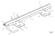
- FIG. 4 shows the unit consisting of the spray doctor system 7 and the support 13 in the uninstalled state outside the printing machine 1.
- the support 13 has support strips 16 between the tabs 14, 15.
- the support strips 16 rest with their upper side on the side facing away from the brush roller 6 bottom of the first tube 8 and are welded to the latter.
- the fastening tabs 14 are each provided with fastening holes 17 for a pin and a screw forming the fastening element 18 (see FIG.
- the fastening tabs 14 are folded away at a right angle to the support strips 16, following the side facing away from the brush roller 6.
- the support tabs 15 are not bent at the bending line 23; Rather, they each have a rectilinear in the fastening tabs 14 merging horizontal arm and a substantially vertical support arm, which faces the second tube 9 upwards.
- the support tabs 15 are bent or folded substantially L-shaped at a bend line between the horizontal arm and the support arm.
- each support tab 15 is formed by two incisions in the carrier 13, wherein the incisions extend at least to the bending line 23 or even beyond this in the respective fastening tabs 14 inside.
- the tubes 8, 9 are each provided with nozzles arranged in a row for the detergent or rinse water.
- the nozzles 22 branch off from the respective channel 10 or 11 (see Figure 2) and are directed to the brush roller 6.
- Figure 5 shows a modification of the spray bar system 7, wherein the two tubes 8, 9 are replaced by a single extrusion 21, in which the two parallel channels 10, 11 extend.
- the strict compression part 21 is made of aluminum and may be coated with a wear-resistant coating, by which the abrasion caused by the bristles is reduced.
- the profile of the extruded part 21 is somewhat constricted in the lying between the channels 10, 11 area, so that even in the extrusion 21 two successively switched doctor blades are available.
- the modification is advantageous in terms of large-scale manufacturing and further in terms of avoiding settling contaminants. Since there is no open gap between the two channels 10, 11, no such gap needs to be sealed by means of a weld in order to prevent the settling of the contaminants in the gap.
- the spray bar system 7 corresponding to the modification shown in Figure 5 can be held by the same carrier 13 as the spray bar system 7 shown in Figures 2 to 4.
- the plate bending part which constitutes the carrier 13 and in 2 to 4 are used.
- This sheet metal part can be z. B. adhered to the extrusion 21 and optionally additionally secured by rivets.
Landscapes
- Inking, Control Or Cleaning Of Printing Machines (AREA)
Applications Claiming Priority (1)
| Application Number | Priority Date | Filing Date | Title |
|---|---|---|---|
| DE102006023896A DE102006023896A1 (de) | 2006-05-22 | 2006-05-22 | Vorrichtung zum Reinigen eines Zylinders einer Druckmaschine |
Publications (3)
| Publication Number | Publication Date |
|---|---|
| EP1859938A2 true EP1859938A2 (fr) | 2007-11-28 |
| EP1859938A3 EP1859938A3 (fr) | 2008-01-16 |
| EP1859938B1 EP1859938B1 (fr) | 2010-12-15 |
Family
ID=38332458
Family Applications (1)
| Application Number | Title | Priority Date | Filing Date |
|---|---|---|---|
| EP07107401A Not-in-force EP1859938B1 (fr) | 2006-05-22 | 2007-05-03 | Dispositif destiné au nettoyage d'un cylindre d'une presse |
Country Status (3)
| Country | Link |
|---|---|
| EP (1) | EP1859938B1 (fr) |
| AT (1) | ATE491575T1 (fr) |
| DE (2) | DE102006023896A1 (fr) |
Cited By (2)
| Publication number | Priority date | Publication date | Assignee | Title |
|---|---|---|---|---|
| CN102896894A (zh) * | 2012-10-15 | 2013-01-30 | 北京印刷学院 | 一种用于橡皮滚筒清洗装置的喷洒机构 |
| CN111097619A (zh) * | 2020-01-18 | 2020-05-05 | 郑州铁头机械科技有限公司 | 一种用于管材表面喷涂印刷文字的设备 |
Families Citing this family (1)
| Publication number | Priority date | Publication date | Assignee | Title |
|---|---|---|---|---|
| CN104553308B (zh) * | 2015-01-23 | 2017-03-15 | 深圳市力嘉创意文化产业发展有限公司 | 一种柔性版的清洗方法及装置 |
Citations (3)
| Publication number | Priority date | Publication date | Assignee | Title |
|---|---|---|---|---|
| EP0388664B1 (fr) | 1989-03-24 | 1993-08-11 | Heidelberger Druckmaschinen Aktiengesellschaft | Dispositif pour nettoyer un cylindre d'imprimerie |
| EP1066965B1 (fr) | 1999-07-07 | 2003-05-14 | MAN Roland Druckmaschinen AG | Dispositif de nettoyage pour l'unité impression d'une machine d'impression rotative |
| EP1151864B1 (fr) | 2000-05-04 | 2006-03-08 | MAN Roland Druckmaschinen AG | Dispositif pour nettoyer un cylindre d'une machine à imprimer |
Family Cites Families (7)
| Publication number | Priority date | Publication date | Assignee | Title |
|---|---|---|---|---|
| DE9415155U1 (de) * | 1994-09-19 | 1994-11-03 | Su, Wu-Shuan, Ta-Li Hsiang, Taichung | Vorrichtung zum Abkratzen eines Plattenzylinders einer Offsetdruckmaschine |
| DE29708470U1 (de) * | 1997-05-13 | 1997-07-10 | MAN Roland Druckmaschinen AG, 63075 Offenbach | Reinigungsvorrichtung für einen Zylinder oder eine Walze einer Druckmaschine |
| DE19753231A1 (de) * | 1997-12-01 | 1999-06-02 | Heidelberger Druckmasch Ag | Vorrichtung zur Reinigung eines Zylinders in einer Druckmaschine |
| DE10040950B4 (de) * | 1999-09-15 | 2009-04-02 | Heidelberger Druckmaschinen Ag | Druckmaschine |
| DE10346659B3 (de) * | 2003-09-10 | 2004-11-18 | Janko Despot | Reinigungseinrichtung für eine zylindrische Fläche in einer Druckmaschine |
| DE102004033771A1 (de) * | 2004-03-16 | 2005-10-13 | Man Roland Druckmaschinen Ag | Druckmaschine und Wascheinrichtung |
| GB2421216A (en) * | 2004-12-16 | 2006-06-21 | G A P Printing Sales Ltd | Apparatus for washing a blanket in an offset printing press |
-
2006
- 2006-05-22 DE DE102006023896A patent/DE102006023896A1/de not_active Withdrawn
-
2007
- 2007-05-03 DE DE502007005926T patent/DE502007005926D1/de active Active
- 2007-05-03 AT AT07107401T patent/ATE491575T1/de active
- 2007-05-03 EP EP07107401A patent/EP1859938B1/fr not_active Not-in-force
Patent Citations (3)
| Publication number | Priority date | Publication date | Assignee | Title |
|---|---|---|---|---|
| EP0388664B1 (fr) | 1989-03-24 | 1993-08-11 | Heidelberger Druckmaschinen Aktiengesellschaft | Dispositif pour nettoyer un cylindre d'imprimerie |
| EP1066965B1 (fr) | 1999-07-07 | 2003-05-14 | MAN Roland Druckmaschinen AG | Dispositif de nettoyage pour l'unité impression d'une machine d'impression rotative |
| EP1151864B1 (fr) | 2000-05-04 | 2006-03-08 | MAN Roland Druckmaschinen AG | Dispositif pour nettoyer un cylindre d'une machine à imprimer |
Cited By (4)
| Publication number | Priority date | Publication date | Assignee | Title |
|---|---|---|---|---|
| CN102896894A (zh) * | 2012-10-15 | 2013-01-30 | 北京印刷学院 | 一种用于橡皮滚筒清洗装置的喷洒机构 |
| CN102896894B (zh) * | 2012-10-15 | 2015-08-12 | 北京印刷学院 | 一种用于橡皮滚筒清洗装置的喷洒机构 |
| CN111097619A (zh) * | 2020-01-18 | 2020-05-05 | 郑州铁头机械科技有限公司 | 一种用于管材表面喷涂印刷文字的设备 |
| CN111097619B (zh) * | 2020-01-18 | 2020-11-03 | 安徽持家汉家居工艺品有限公司 | 一种用于管材表面喷涂印刷文字的设备 |
Also Published As
| Publication number | Publication date |
|---|---|
| DE502007005926D1 (de) | 2011-01-27 |
| EP1859938A3 (fr) | 2008-01-16 |
| ATE491575T1 (de) | 2011-01-15 |
| EP1859938B1 (fr) | 2010-12-15 |
| DE102006023896A1 (de) | 2007-11-29 |
Similar Documents
| Publication | Publication Date | Title |
|---|---|---|
| DE102007013590A1 (de) | Verfahren und Vorrichtung zur Reinigung von Düsen an einem Sprühfeuchtwerk | |
| DE69718007T2 (de) | Vorrichtung und verfahren zum reinigen von flexographischen druckplatten | |
| DE102019105227B4 (de) | Schaber mit Wasserschmierung | |
| EP1859938B1 (fr) | Dispositif destiné au nettoyage d'un cylindre d'une presse | |
| DE102007025983B4 (de) | Reinigungsvorrichtung für Druckmaschinen mit gefedeter Rakel | |
| DE1204516B (de) | Abstreifvorrichtung zur Verwendung bei der Beschichtung von Tafeln oder Bahnen | |
| WO2008043506A2 (fr) | Dispositif de nettoyage d'un cylindre d'impression | |
| EP0878304B1 (fr) | Dispositif de nettoyage pour un cylindre ou un rouleau d'une machine d'impression | |
| EP0591634A1 (fr) | Dispositif de nettoyage pour cylindre de machine à imprimer | |
| DE60306362T2 (de) | Düsen für eine reinigungsanlage einer druckmaschine | |
| DE102011103804B4 (de) | Sprühstange zum Sprühen einer Flüssigkeit in einer Druckmaschine | |
| EP1066965B1 (fr) | Dispositif de nettoyage pour l'unité impression d'une machine d'impression rotative | |
| EP1743771A1 (fr) | Dispositif pour nettoyer des cylindres d'une machine d'impression | |
| WO2010049141A1 (fr) | Procédé de fabrication d'une unité d'impression sérigraphique et unité d'impression sérigraphique | |
| EP2119564B1 (fr) | Boîtier de mécanisme de mouillage | |
| EP1244550B1 (fr) | Barre de nettoyage pour cylindre de machine a imprimer | |
| WO2013029989A1 (fr) | Dispositif de fixation de lames de docteur | |
| DE102008004073B4 (de) | Vorrichtung zum Reinigen von Zylindern einer Druckmaschine | |
| DE102011081925B4 (de) | Vorrichtung zum Halten von Schaberklingen | |
| DE102007027385B4 (de) | Farbkammer für ein Farbwerk einer Rotationsdruckmaschine und Verfahren zur Herstellung einer solchen Farbkammer | |
| WO2001051286A1 (fr) | Barre de nettoyage pour cylindre de machine a imprimer | |
| DE9213605U1 (de) | Druckmaschinenzylinder-Waschvorrichtung | |
| DE19800371A1 (de) | Vorrichtung zum Abtragen von Faserflocken und Verfahren zur Herstellung von Zähnen einer Abtragwalze | |
| DE102010005760A1 (de) | Wellrohr-Innenreinigung und Vorrichtung dazu | |
| DE102008017275B4 (de) | Befeuchtungsvorrichtung eines Sprühfeuchtwerks |
Legal Events
| Date | Code | Title | Description |
|---|---|---|---|
| PUAI | Public reference made under article 153(3) epc to a published international application that has entered the european phase |
Free format text: ORIGINAL CODE: 0009012 |
|
| AK | Designated contracting states |
Kind code of ref document: A2 Designated state(s): AT BE BG CH CY CZ DE DK EE ES FI FR GB GR HU IE IS IT LI LT LU LV MC MT NL PL PT RO SE SI SK TR |
|
| AX | Request for extension of the european patent |
Extension state: AL BA HR MK YU |
|
| PUAL | Search report despatched |
Free format text: ORIGINAL CODE: 0009013 |
|
| AK | Designated contracting states |
Kind code of ref document: A3 Designated state(s): AT BE BG CH CY CZ DE DK EE ES FI FR GB GR HU IE IS IT LI LT LU LV MC MT NL PL PT RO SE SI SK TR |
|
| AX | Request for extension of the european patent |
Extension state: AL BA HR MK YU |
|
| 17P | Request for examination filed |
Effective date: 20080716 |
|
| AKX | Designation fees paid |
Designated state(s): AT BE BG CH CY CZ DE DK EE ES FI FR GB GR HU IE IS IT LI LT LU LV MC MT NL PL PT RO SE SI SK TR |
|
| 17Q | First examination report despatched |
Effective date: 20081014 |
|
| GRAP | Despatch of communication of intention to grant a patent |
Free format text: ORIGINAL CODE: EPIDOSNIGR1 |
|
| GRAS | Grant fee paid |
Free format text: ORIGINAL CODE: EPIDOSNIGR3 |
|
| GRAA | (expected) grant |
Free format text: ORIGINAL CODE: 0009210 |
|
| AK | Designated contracting states |
Kind code of ref document: B1 Designated state(s): AT BE BG CH CY CZ DE DK EE ES FI FR GB GR HU IE IS IT LI LT LU LV MC MT NL PL PT RO SE SI SK TR |
|
| REG | Reference to a national code |
Ref country code: GB Ref legal event code: FG4D Free format text: NOT ENGLISH Ref country code: CH Ref legal event code: EP |
|
| REG | Reference to a national code |
Ref country code: IE Ref legal event code: FG4D |
|
| REF | Corresponds to: |
Ref document number: 502007005926 Country of ref document: DE Date of ref document: 20110127 Kind code of ref document: P |
|
| REG | Reference to a national code |
Ref country code: NL Ref legal event code: VDEP Effective date: 20101215 |
|
| PG25 | Lapsed in a contracting state [announced via postgrant information from national office to epo] |
Ref country code: LT Free format text: LAPSE BECAUSE OF FAILURE TO SUBMIT A TRANSLATION OF THE DESCRIPTION OR TO PAY THE FEE WITHIN THE PRESCRIBED TIME-LIMIT Effective date: 20101215 |
|
| LTIE | Lt: invalidation of european patent or patent extension |
Effective date: 20101215 |
|
| PG25 | Lapsed in a contracting state [announced via postgrant information from national office to epo] |
Ref country code: CY Free format text: LAPSE BECAUSE OF FAILURE TO SUBMIT A TRANSLATION OF THE DESCRIPTION OR TO PAY THE FEE WITHIN THE PRESCRIBED TIME-LIMIT Effective date: 20101215 Ref country code: BG Free format text: LAPSE BECAUSE OF FAILURE TO SUBMIT A TRANSLATION OF THE DESCRIPTION OR TO PAY THE FEE WITHIN THE PRESCRIBED TIME-LIMIT Effective date: 20110315 Ref country code: NL Free format text: LAPSE BECAUSE OF FAILURE TO SUBMIT A TRANSLATION OF THE DESCRIPTION OR TO PAY THE FEE WITHIN THE PRESCRIBED TIME-LIMIT Effective date: 20101215 Ref country code: SI Free format text: LAPSE BECAUSE OF FAILURE TO SUBMIT A TRANSLATION OF THE DESCRIPTION OR TO PAY THE FEE WITHIN THE PRESCRIBED TIME-LIMIT Effective date: 20101215 Ref country code: LV Free format text: LAPSE BECAUSE OF FAILURE TO SUBMIT A TRANSLATION OF THE DESCRIPTION OR TO PAY THE FEE WITHIN THE PRESCRIBED TIME-LIMIT Effective date: 20101215 Ref country code: FI Free format text: LAPSE BECAUSE OF FAILURE TO SUBMIT A TRANSLATION OF THE DESCRIPTION OR TO PAY THE FEE WITHIN THE PRESCRIBED TIME-LIMIT Effective date: 20101215 Ref country code: SE Free format text: LAPSE BECAUSE OF FAILURE TO SUBMIT A TRANSLATION OF THE DESCRIPTION OR TO PAY THE FEE WITHIN THE PRESCRIBED TIME-LIMIT Effective date: 20101215 |
|
| REG | Reference to a national code |
Ref country code: IE Ref legal event code: FD4D |
|
| PG25 | Lapsed in a contracting state [announced via postgrant information from national office to epo] |
Ref country code: EE Free format text: LAPSE BECAUSE OF FAILURE TO SUBMIT A TRANSLATION OF THE DESCRIPTION OR TO PAY THE FEE WITHIN THE PRESCRIBED TIME-LIMIT Effective date: 20101215 Ref country code: IS Free format text: LAPSE BECAUSE OF FAILURE TO SUBMIT A TRANSLATION OF THE DESCRIPTION OR TO PAY THE FEE WITHIN THE PRESCRIBED TIME-LIMIT Effective date: 20110415 Ref country code: GR Free format text: LAPSE BECAUSE OF FAILURE TO SUBMIT A TRANSLATION OF THE DESCRIPTION OR TO PAY THE FEE WITHIN THE PRESCRIBED TIME-LIMIT Effective date: 20110316 Ref country code: PT Free format text: LAPSE BECAUSE OF FAILURE TO SUBMIT A TRANSLATION OF THE DESCRIPTION OR TO PAY THE FEE WITHIN THE PRESCRIBED TIME-LIMIT Effective date: 20110415 Ref country code: CZ Free format text: LAPSE BECAUSE OF FAILURE TO SUBMIT A TRANSLATION OF THE DESCRIPTION OR TO PAY THE FEE WITHIN THE PRESCRIBED TIME-LIMIT Effective date: 20101215 Ref country code: IE Free format text: LAPSE BECAUSE OF FAILURE TO SUBMIT A TRANSLATION OF THE DESCRIPTION OR TO PAY THE FEE WITHIN THE PRESCRIBED TIME-LIMIT Effective date: 20101215 Ref country code: ES Free format text: LAPSE BECAUSE OF FAILURE TO SUBMIT A TRANSLATION OF THE DESCRIPTION OR TO PAY THE FEE WITHIN THE PRESCRIBED TIME-LIMIT Effective date: 20110326 |
|
| PG25 | Lapsed in a contracting state [announced via postgrant information from national office to epo] |
Ref country code: RO Free format text: LAPSE BECAUSE OF FAILURE TO SUBMIT A TRANSLATION OF THE DESCRIPTION OR TO PAY THE FEE WITHIN THE PRESCRIBED TIME-LIMIT Effective date: 20101215 Ref country code: PL Free format text: LAPSE BECAUSE OF FAILURE TO SUBMIT A TRANSLATION OF THE DESCRIPTION OR TO PAY THE FEE WITHIN THE PRESCRIBED TIME-LIMIT Effective date: 20101215 Ref country code: SK Free format text: LAPSE BECAUSE OF FAILURE TO SUBMIT A TRANSLATION OF THE DESCRIPTION OR TO PAY THE FEE WITHIN THE PRESCRIBED TIME-LIMIT Effective date: 20101215 |
|
| PLBE | No opposition filed within time limit |
Free format text: ORIGINAL CODE: 0009261 |
|
| STAA | Information on the status of an ep patent application or granted ep patent |
Free format text: STATUS: NO OPPOSITION FILED WITHIN TIME LIMIT |
|
| PG25 | Lapsed in a contracting state [announced via postgrant information from national office to epo] |
Ref country code: DK Free format text: LAPSE BECAUSE OF FAILURE TO SUBMIT A TRANSLATION OF THE DESCRIPTION OR TO PAY THE FEE WITHIN THE PRESCRIBED TIME-LIMIT Effective date: 20101215 |
|
| 26N | No opposition filed |
Effective date: 20110916 |
|
| BERE | Be: lapsed |
Owner name: HEIDELBERGER DRUCKMASCHINEN A.G. Effective date: 20110531 |
|
| PG25 | Lapsed in a contracting state [announced via postgrant information from national office to epo] |
Ref country code: MT Free format text: LAPSE BECAUSE OF FAILURE TO SUBMIT A TRANSLATION OF THE DESCRIPTION OR TO PAY THE FEE WITHIN THE PRESCRIBED TIME-LIMIT Effective date: 20101215 Ref country code: IT Free format text: LAPSE BECAUSE OF FAILURE TO SUBMIT A TRANSLATION OF THE DESCRIPTION OR TO PAY THE FEE WITHIN THE PRESCRIBED TIME-LIMIT Effective date: 20101215 Ref country code: MC Free format text: LAPSE BECAUSE OF NON-PAYMENT OF DUE FEES Effective date: 20110531 |
|
| REG | Reference to a national code |
Ref country code: CH Ref legal event code: PL |
|
| REG | Reference to a national code |
Ref country code: DE Ref legal event code: R097 Ref document number: 502007005926 Country of ref document: DE Effective date: 20110916 |
|
| PG25 | Lapsed in a contracting state [announced via postgrant information from national office to epo] |
Ref country code: LI Free format text: LAPSE BECAUSE OF NON-PAYMENT OF DUE FEES Effective date: 20110531 Ref country code: CH Free format text: LAPSE BECAUSE OF NON-PAYMENT OF DUE FEES Effective date: 20110531 |
|
| PG25 | Lapsed in a contracting state [announced via postgrant information from national office to epo] |
Ref country code: BE Free format text: LAPSE BECAUSE OF NON-PAYMENT OF DUE FEES Effective date: 20110531 |
|
| PG25 | Lapsed in a contracting state [announced via postgrant information from national office to epo] |
Ref country code: LU Free format text: LAPSE BECAUSE OF NON-PAYMENT OF DUE FEES Effective date: 20110503 |
|
| REG | Reference to a national code |
Ref country code: AT Ref legal event code: MM01 Ref document number: 491575 Country of ref document: AT Kind code of ref document: T Effective date: 20120503 |
|
| PG25 | Lapsed in a contracting state [announced via postgrant information from national office to epo] |
Ref country code: AT Free format text: LAPSE BECAUSE OF NON-PAYMENT OF DUE FEES Effective date: 20120503 |
|
| PG25 | Lapsed in a contracting state [announced via postgrant information from national office to epo] |
Ref country code: TR Free format text: LAPSE BECAUSE OF FAILURE TO SUBMIT A TRANSLATION OF THE DESCRIPTION OR TO PAY THE FEE WITHIN THE PRESCRIBED TIME-LIMIT Effective date: 20101215 |
|
| PG25 | Lapsed in a contracting state [announced via postgrant information from national office to epo] |
Ref country code: HU Free format text: LAPSE BECAUSE OF FAILURE TO SUBMIT A TRANSLATION OF THE DESCRIPTION OR TO PAY THE FEE WITHIN THE PRESCRIBED TIME-LIMIT Effective date: 20101215 |
|
| REG | Reference to a national code |
Ref country code: FR Ref legal event code: PLFP Year of fee payment: 9 |
|
| PGFP | Annual fee paid to national office [announced via postgrant information from national office to epo] |
Ref country code: GB Payment date: 20150518 Year of fee payment: 9 Ref country code: DE Payment date: 20150531 Year of fee payment: 9 |
|
| PGFP | Annual fee paid to national office [announced via postgrant information from national office to epo] |
Ref country code: FR Payment date: 20150518 Year of fee payment: 9 |
|
| REG | Reference to a national code |
Ref country code: DE Ref legal event code: R119 Ref document number: 502007005926 Country of ref document: DE |
|
| GBPC | Gb: european patent ceased through non-payment of renewal fee |
Effective date: 20160503 |
|
| REG | Reference to a national code |
Ref country code: FR Ref legal event code: ST Effective date: 20170131 |
|
| PG25 | Lapsed in a contracting state [announced via postgrant information from national office to epo] |
Ref country code: FR Free format text: LAPSE BECAUSE OF NON-PAYMENT OF DUE FEES Effective date: 20160531 Ref country code: DE Free format text: LAPSE BECAUSE OF NON-PAYMENT OF DUE FEES Effective date: 20161201 |
|
| PG25 | Lapsed in a contracting state [announced via postgrant information from national office to epo] |
Ref country code: GB Free format text: LAPSE BECAUSE OF NON-PAYMENT OF DUE FEES Effective date: 20160503 |