EP1859967A1 - Pneumatique et procede pour sa fabrication - Google Patents
Pneumatique et procede pour sa fabrication Download PDFInfo
- Publication number
- EP1859967A1 EP1859967A1 EP06715537A EP06715537A EP1859967A1 EP 1859967 A1 EP1859967 A1 EP 1859967A1 EP 06715537 A EP06715537 A EP 06715537A EP 06715537 A EP06715537 A EP 06715537A EP 1859967 A1 EP1859967 A1 EP 1859967A1
- Authority
- EP
- European Patent Office
- Prior art keywords
- tire
- gas vent
- vent hole
- pneumatic tire
- layer
- Prior art date
- Legal status (The legal status is an assumption and is not a legal conclusion. Google has not performed a legal analysis and makes no representation as to the accuracy of the status listed.)
- Withdrawn
Links
Images

Classifications
-
- B—PERFORMING OPERATIONS; TRANSPORTING
- B60—VEHICLES IN GENERAL
- B60C—VEHICLE TYRES; TYRE INFLATION; TYRE CHANGING; CONNECTING VALVES TO INFLATABLE ELASTIC BODIES IN GENERAL; DEVICES OR ARRANGEMENTS RELATED TO TYRES
- B60C19/00—Tyre parts or constructions not otherwise provided for
- B60C19/12—Puncture preventing arrangements
- B60C19/122—Puncture preventing arrangements disposed inside of the inner liner
-
- B—PERFORMING OPERATIONS; TRANSPORTING
- B29—WORKING OF PLASTICS; WORKING OF SUBSTANCES IN A PLASTIC STATE IN GENERAL
- B29C—SHAPING OR JOINING OF PLASTICS; SHAPING OF MATERIAL IN A PLASTIC STATE, NOT OTHERWISE PROVIDED FOR; AFTER-TREATMENT OF THE SHAPED PRODUCTS, e.g. REPAIRING
- B29C73/00—Repairing of articles made from plastics or substances in a plastic state, e.g. of articles shaped or produced by using techniques covered by this subclass or subclass B29D
- B29C73/16—Auto-repairing or self-sealing arrangements or agents
- B29C73/18—Auto-repairing or self-sealing arrangements or agents the article material itself being self-sealing, e.g. by compression
- B29C73/20—Auto-repairing or self-sealing arrangements or agents the article material itself being self-sealing, e.g. by compression the article material only consisting in part of a deformable sealing material
-
- B—PERFORMING OPERATIONS; TRANSPORTING
- B29—WORKING OF PLASTICS; WORKING OF SUBSTANCES IN A PLASTIC STATE IN GENERAL
- B29D—PRODUCING PARTICULAR ARTICLES FROM PLASTICS OR FROM SUBSTANCES IN A PLASTIC STATE
- B29D30/00—Producing pneumatic or solid tyres or parts thereof
- B29D30/0061—Accessories, details or auxiliary operations not otherwise provided for
-
- B—PERFORMING OPERATIONS; TRANSPORTING
- B29—WORKING OF PLASTICS; WORKING OF SUBSTANCES IN A PLASTIC STATE IN GENERAL
- B29D—PRODUCING PARTICULAR ARTICLES FROM PLASTICS OR FROM SUBSTANCES IN A PLASTIC STATE
- B29D30/00—Producing pneumatic or solid tyres or parts thereof
- B29D30/06—Pneumatic tyres or parts thereof (e.g. produced by casting, moulding, compression moulding, injection moulding, centrifugal casting)
- B29D30/0681—Parts of pneumatic tyres; accessories, auxiliary operations
- B29D30/0685—Incorporating auto-repairing or self-sealing arrangements or agents on or into tyres
-
- B—PERFORMING OPERATIONS; TRANSPORTING
- B60—VEHICLES IN GENERAL
- B60C—VEHICLE TYRES; TYRE INFLATION; TYRE CHANGING; CONNECTING VALVES TO INFLATABLE ELASTIC BODIES IN GENERAL; DEVICES OR ARRANGEMENTS RELATED TO TYRES
- B60C1/00—Tyres characterised by the chemical composition or the physical arrangement or mixture of the composition
- B60C1/0008—Compositions of the inner liner
-
- B—PERFORMING OPERATIONS; TRANSPORTING
- B60—VEHICLES IN GENERAL
- B60C—VEHICLE TYRES; TYRE INFLATION; TYRE CHANGING; CONNECTING VALVES TO INFLATABLE ELASTIC BODIES IN GENERAL; DEVICES OR ARRANGEMENTS RELATED TO TYRES
- B60C19/00—Tyre parts or constructions not otherwise provided for
- B60C19/12—Puncture preventing arrangements
-
- B—PERFORMING OPERATIONS; TRANSPORTING
- B60—VEHICLES IN GENERAL
- B60C—VEHICLE TYRES; TYRE INFLATION; TYRE CHANGING; CONNECTING VALVES TO INFLATABLE ELASTIC BODIES IN GENERAL; DEVICES OR ARRANGEMENTS RELATED TO TYRES
- B60C5/00—Inflatable pneumatic tyres or inner tubes
- B60C5/12—Inflatable pneumatic tyres or inner tubes without separate inflatable inserts, e.g. tubeless tyres with transverse section open to the rim
- B60C5/14—Inflatable pneumatic tyres or inner tubes without separate inflatable inserts, e.g. tubeless tyres with transverse section open to the rim with impervious liner or coating on the inner wall of the tyre
- B60C5/142—Inflatable pneumatic tyres or inner tubes without separate inflatable inserts, e.g. tubeless tyres with transverse section open to the rim with impervious liner or coating on the inner wall of the tyre provided partially, i.e. not covering the whole inner wall
-
- C—CHEMISTRY; METALLURGY
- C08—ORGANIC MACROMOLECULAR COMPOUNDS; THEIR PREPARATION OR CHEMICAL WORKING-UP; COMPOSITIONS BASED THEREON
- C08K—Use of inorganic or non-macromolecular organic substances as compounding ingredients
- C08K5/00—Use of organic ingredients
- C08K5/04—Oxygen-containing compounds
- C08K5/14—Peroxides
-
- B—PERFORMING OPERATIONS; TRANSPORTING
- B29—WORKING OF PLASTICS; WORKING OF SUBSTANCES IN A PLASTIC STATE IN GENERAL
- B29D—PRODUCING PARTICULAR ARTICLES FROM PLASTICS OR FROM SUBSTANCES IN A PLASTIC STATE
- B29D30/00—Producing pneumatic or solid tyres or parts thereof
- B29D30/06—Pneumatic tyres or parts thereof (e.g. produced by casting, moulding, compression moulding, injection moulding, centrifugal casting)
- B29D30/0681—Parts of pneumatic tyres; accessories, auxiliary operations
- B29D30/0685—Incorporating auto-repairing or self-sealing arrangements or agents on or into tyres
- B29D2030/0686—Incorporating sealants on or into tyres not otherwise provided for; auxiliary operations therefore, e.g. preparation of the tyre
- B29D2030/0695—Incorporating sealants on or into tyres not otherwise provided for; auxiliary operations therefore, e.g. preparation of the tyre the sealant being in the form of one wide strip, e.g. a patch
-
- B—PERFORMING OPERATIONS; TRANSPORTING
- B29—WORKING OF PLASTICS; WORKING OF SUBSTANCES IN A PLASTIC STATE IN GENERAL
- B29L—INDEXING SCHEME ASSOCIATED WITH SUBCLASS B29C, RELATING TO PARTICULAR ARTICLES
- B29L2030/00—Pneumatic or solid tyres or parts thereof
Definitions
- the present invention relates to a pneumatic tire and a method of manufacturing the same. Specifically, the present invention relates to a pneumatic tire with improved uniformity by disposing a tacky sealant layer that is formed of a rubber component thermally decomposable with a peroxide on the inner side of the tread portion, and relates also to a method of manufacturing such a pneumatic tire.
- Patent Document 1 proposes a technique using a characteristic of polyisobutylene rubber, which is thermally decomposable with a peroxide.
- a rubber composition containing polyisobutylene rubber and peroxide is disposed on the inner side of a tread portion of a green tire, and is modified into a sealant by using the heat at the time of curing.
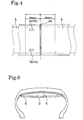
- a sealant layer is formed by using this technique, a large amount of decomposition gas is generated due to the decomposition reaction of the rubber component, and the resultant decomposition gas G is filled between a tacky sealant layer 5 and a cover rubber layer 6 as shown in Fig. 6.
- the sealant of the tacky sealant layer 5 flows non-uniformly, resulting in a problem of deterioration in the uniformity of the tire.
- Patent Document 2 discloses another method, in which twisted yarn for allowing decomposition gas to escape is provided between a tacky sealant layer and a cover rubber layer in a manner of penetrating from the inside to the outside.
- Patent Document 1 Japanese Patent Application Kokai Publication No. Sho 53-55802
- Patent Document 2 Japanese Patent Application Kokai Publication No. 2004-332811
- An object of the present invention is to provide a pneumatic tire that securely improves the deterioration in its uniformity, which deterioration derives from decomposition gas generated when a tacky sealant layer is formed by decomposition. Providing a method of manufacturing such tire is another object of the invention.
- a pneumatic tire according to the present invention for achieving the above-described object is characterized by including: a tacky sealant layer which is formed of a rubber component thermally decomposable with a peroxide, and which is disposed on the inner wall surface of the tire at least in a region corresponding to a tread portion; a cover rubber layer which covers the tacky sealant layer; and at least one gas vent hole which is formed in the cover rubber layer.
- a method of manufacturing a pneumatic tire according to the present invention is characterized by including the steps of: disposing a rubber component thermally decomposable with a peroxide on the inner wall surface of a tire at least in a region corresponding to a tread portion in a manner that the rubber component is covered with a cover rubber layer; forming a tacky sealant layer by decomposing the rubber component with the peroxide at the time of curing; and forming at least one gas vent hole in the cover rubber layer of the tire after the curing so as to discharge, from the gas vent hole, decomposition gas generated at the time of the curing.
- the gas vent hole is formed in the cover rubber layer, so that decomposition gas generated at the time of forming the tacky sealant layer by thermal decomposition is quickly discharged through the gas vent hole to the outside of the tire.
- This makes it possible to maintain the uniformity of the tire for a long time without allowing decomposition gas between the tacky sealant layer and the cover rubber layer to remain therebetween at the time of the running of the tire.
- the present invention provides an excellent sealing effect when the tire runs over a nail to be punctured.
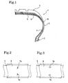
- a pneumatic tire T shown in Figs. 1 and 2 is provided with: a tread portion 1; a pair of right and left bead portions 2; and a pair of right and left side wall portions 3, which connect the tread portion 1 to the corresponding bead portions 2.
- a carcass layer 8 extends from the tread portion 1 to the bead portions 2 respectively via the side wall portions 3, and is laid between the right and left beads paired with each other. Each of the end portions of the carcass layer 8 is locked around a corresponding bead in a manner that the end portion is folded back from the inner side of the tire to the outer side thereof around the bead.
- a tacky sealant layer 5 is disposed, on the inner peripheral side of an inner liner layer 4, and in a region corresponding to the tread portion 1, and is covered with a cover rubber layer 6.
- the tacky sealant layer 5 is formed in a way that a rubber component such as polyisobutylene rubber is thermally decomposed with a peroxide at the time of curing.
- the tacky sealant layer 5 has only to be disposed on the inner wall surface of the tire at least in a region corresponding to the tread portion, and may extend further to regions corresponding respectively to the side wall portions.
- the tacky sealant layer 5 is disposed on the inner peripheral side of the inner liner layer 4, but may be disposed between the outer peripheral side of the inner liner layer 4 and the carcass layer 8. In the latter case, a part of the inner liner layer 4 also serves as the cover rubber layer 6.
- two gas vent holes 7a are formed respectively in the two end portions of the cover rubber layer 6 in the tire width direction. As to be described in descriptions of a manufacturing method, these gas vent holes 7a are provided by notching the cover rubber layer 6 after the tire is cured to be shaped.
- Decomposition gas which is generated when the tacky sealant layer 5 is formed by thermal decomposition during the curing, is discharged through the gas vent holes 7a to the outside of the tire.
- the remaining decomposition gas which has not been discharged by a discharging operation after the curing of the tire, may be discharged to a cavity portion in the tire through the running of the tire.
- each gas vent hole 7a it is preferable to form each gas vent hole 7a into a slit shape as shown in Fig. 2 because the tacky sealant layer 5 will be exposed to the minimum. It is more preferable that the slit shape be bent into a hook shape as shown in Fig. 2.
- the shape of each gas vent hole 7a is not limited to the slit shape, may be an oval shape as shown in Fig. 3, and may alternatively be a circular or polygonal shape.
- the size of each gas vent hole is represented by the maximum diameter of the circumcircle surrounding the gas vent hole, it is preferable that the size be 5 mm to 15 mm.
- the size is less than 5 mm, the efficiency in discharging the decomposition gas is reduced.
- the size is more than 15 mm, the sticking trouble is more likely to occur due to the exposure of the tacky sealant layer.
- a porous sheet of net, textile fabric or the like may be provided to the gas vent holes in the manner of covering the gas vent holes. This porous sheet makes it possible to avoid troubles caused when the tacky sealant layer is in touch.
- the gas vent holes are preferably formed respectively in the two end portions of the cover rubber layer in the tire width direction.
- the gas vent holes are positioned in the center region of the cover rubber layer in the tire width direction.
- the number of gas vent holes is at least one on each end portion in the tire width direction. However, the number be preferably enough to be one on each side.
- each gas vent holes in the tire circumferential direction, is preferably in a vicinity of a spliced portion where both edge portions of the cover rubber layer are bonded to each other in the tire circumferential direction.
- This spliced portion is formed thicker than the other portion because the edge portions of the cover rubber layer overlap each other. Accordingly, the spliced portion is easily brought into close contact with the inner liner layer side by the centrifugal force at the time of the running.
- the tacky sealant layer positioned on the outer side of the spliced portion of the cover rubber layer is pressed to the inner liner layer side, so that decomposition gas remaining inside is more likely to gather in a vicinity of the spliced portion than the other portion. Consequently, the forming of the gas vent holes in a vicinity of the spliced portion makes it possible to efficiently discharge the gas.
- the gas vent holes 7a (7b) be formed within a region w extending from the center by 10 cm or less on each side of the center in the tire circumferential direction.
- one or more of the gas vent hole be formed in each side of the region w in the tire width direction.
- a rubber component to be decomposed with a peroxide isobutylene rubber, isobutylene-isoprene rubber (IIR), isoprene rubber or the like are used.
- IIR isobutylene-isoprene rubber
- another rubber component with the rubber composition composing the tacky sealant layer 5 in addition to the peroxide-decomposable rubber component, for the purpose of adjusting the viscosity.
- this rubber component for example, styrene-butadiene rubber, butadiene rubber or natural rubber can be given.
- acyl peroxides for example, benzoyl peroxide, p-chlorobenzoyl peroxide
- ketone peroxides for example, methyl ethyl ketone peroxide
- peroxyesters for example, t-butyl peroxyacetate, t-butyl peroxybenzoate, t-butyl peroxyphthalate
- alkyl peroxides for example, dicumyl peroxide, di-t-butyl peroxybenzoate, 1,3-bis(t-butyl peroxyisopropyl)benzen
- hydroperoxides for example, t-butyl hydroperoxide
- a catalyst such as cobalt naphthenate may be added to the rubber composition composing the sealant layer as necessarily for the purpose of accelerating the decomposing of the rubber component with the peroxide.
- an inorganic filler such as carbon black and silica; a takiness agent such as polybutene; or a plasticizer such as aromatic process oil, naphthenic process oil and paraffinic process oil are added to the rubber composition.
- the rubber composition composing the tacky sealant layer 5 in the present invention is formed by adding 0.2 to 20 parts by weight of the peroxide to 100 parts by weight of the rubber component which is decomposed with the peroxide. Such a rubber composition is in a solid state at the time of forming. Then, the rubber component in the rubber composition is decomposed to be a sealant material by the heating at the time of the curing, thus having a tackiness in a tire after the curing.
- a peroxide and a rubber component which is decomposed with the peroxide, are firstly disposed on the inner wall surface of a green tire at least in a region corresponding to a tread portion in a manner that the peroxide and the rubber component are covered with a cover rubber layer at the time of forming the green tire. Then, when the green tire is set and cured in a mold, the rubber component is thermally decomposed with the peroxide so as to be modified into a tacky sealant layer. Subsequently, as shown in Fig. 2 or Fig. 3, at least one gas vent hole 7a or 7b is formed by notching the cover rubber layer of the tire after the curing.
- decomposition gas generated at the time of curing is discharged to the outside of the tire.
- the gas may be caused to spontaneously flow out to be discharged, but it is preferable that the gas be purposefully discharged by pressing the cover rubber layer from the tire inner surface side, for example.
- the inner surface side of the tire may be depressurized so that the decomposition gas is sucked and removed.
- This depressurization and suction makes it possible to discharge almost all of the decomposition gas.
- the gas vent holes are sealed with a sealing member or the like after the gas is discharged. The sealing of the gas vent holes prevents the outside air from flowing back to the inside of the cover rubber layer. Accordingly, a non-uniform flow of the sealant of the tacky sealant layer is prevented so that the uniformity is much more favorably improved than otherwise.
- the pneumatic tires as shown in Fig. 1 were formed and then cured by using a rubber composition composing a tacky sealant layer, which is compounded by adding 12 parts by weight of a peroxide (dicumyl peroxide) to 100 parts by weight of polyisobutylene rubber.
- a peroxide dicumyl peroxide
- two circular gas vent holes (a diameter of 10 mm) were formed in a cover rubber layer, and were sealed with a sealing member after gas was discharged forcedly by vacuuming.
- gas vent holes were not formed in the cover rubber layer.
Landscapes
- Engineering & Computer Science (AREA)
- Mechanical Engineering (AREA)
- Chemical & Material Sciences (AREA)
- Health & Medical Sciences (AREA)
- Chemical Kinetics & Catalysis (AREA)
- Medicinal Chemistry (AREA)
- Polymers & Plastics (AREA)
- Organic Chemistry (AREA)
- Tires In General (AREA)
- Tyre Moulding (AREA)
Applications Claiming Priority (2)
| Application Number | Priority Date | Filing Date | Title |
|---|---|---|---|
| JP2005069415A JP4559265B2 (ja) | 2005-03-11 | 2005-03-11 | 空気入りタイヤ及びその製造方法 |
| PCT/JP2006/304767 WO2006095862A1 (fr) | 2005-03-11 | 2006-03-10 | Pneumatique et procede pour sa fabrication |
Publications (2)
| Publication Number | Publication Date |
|---|---|
| EP1859967A1 true EP1859967A1 (fr) | 2007-11-28 |
| EP1859967A4 EP1859967A4 (fr) | 2009-07-29 |
Family
ID=36953451
Family Applications (1)
| Application Number | Title | Priority Date | Filing Date |
|---|---|---|---|
| EP06715537A Withdrawn EP1859967A4 (fr) | 2005-03-11 | 2006-03-10 | Pneumatique et procede pour sa fabrication |
Country Status (4)
| Country | Link |
|---|---|
| EP (1) | EP1859967A4 (fr) |
| JP (1) | JP4559265B2 (fr) |
| CN (1) | CN101137521B (fr) |
| WO (1) | WO2006095862A1 (fr) |
Cited By (4)
| Publication number | Priority date | Publication date | Assignee | Title |
|---|---|---|---|---|
| EP2119577A1 (fr) | 2008-05-13 | 2009-11-18 | The Yokohama Rubber Co., Ltd. | Pneu |
| WO2010018124A1 (fr) * | 2008-08-14 | 2010-02-18 | Societe De Technologie Michelin | Pneu sans chambre à air comprenant un revêtement interne fendu, et son procédé de fabrication |
| EP3126129A4 (fr) * | 2014-12-16 | 2017-12-13 | Triangle Tyre Co.,Ltd | Pneu ayant des couches d'obturation multiple intégrées et son procédé de préparation |
| US20230219310A1 (en) * | 2020-06-19 | 2023-07-13 | The Yokohama Rubber Co., Ltd. | Pneumatic tire |
Families Citing this family (5)
| Publication number | Priority date | Publication date | Assignee | Title |
|---|---|---|---|---|
| US7607466B2 (en) * | 2006-10-27 | 2009-10-27 | Daniel Kim | Self-sealing tire |
| US8617333B2 (en) | 2007-09-20 | 2013-12-31 | The Goodyear Tire & Rubber Company | Pneumatic tire having built-in sealant layer and preparation thereof |
| US20090078353A1 (en) * | 2007-09-21 | 2009-03-26 | Ramendra Nath Majumdar | Pneumatic Tire Having Built-In Sealant Layer And Preparation Thereof |
| US8316903B2 (en) * | 2007-10-01 | 2012-11-27 | The Goodyear Tire & Rubber Company | Pneumatic tire having built-in sealant layer and preparation thereof |
| JP6382095B2 (ja) * | 2014-12-17 | 2018-08-29 | 東洋ゴム工業株式会社 | タイヤゴム部材間の接続構造及びタイヤ |
Family Cites Families (10)
| Publication number | Priority date | Publication date | Assignee | Title |
|---|---|---|---|---|
| JPS5855197B2 (ja) | 1976-10-27 | 1983-12-08 | オ−ツタイヤ株式会社 | パンク防止用粘着シ−ラント組成物層を備えた空気入りタイヤ |
| US4228839A (en) * | 1978-08-03 | 1980-10-21 | The Firestone Tire & Rubber Company | Self-sealing pneumatic tire |
| US4539344A (en) * | 1981-08-31 | 1985-09-03 | Rockcor, Inc. | Thermally stable sealant composition |
| US4664168A (en) | 1985-01-22 | 1987-05-12 | The Uniroyal Goodrich Tire Company | Self-sealing tire with edge strips for tire sealant |
| JP4232926B2 (ja) * | 1999-06-03 | 2009-03-04 | 住友ゴム工業株式会社 | 空気入りタイヤの製造方法 |
| JP2003080909A (ja) * | 2001-09-14 | 2003-03-19 | Yokohama Rubber Co Ltd:The | 空気入りタイヤ及びその製造方法 |
| DE60225460T2 (de) * | 2001-09-14 | 2009-02-26 | Honda Giken Kogyo K.K. | Luftreifen mit einer Versiegelungsschicht und Verfahren zu seiner Herstellung |
| JP4409814B2 (ja) * | 2001-09-26 | 2010-02-03 | 横浜ゴム株式会社 | 粘着シーラント層を備えた空気入りタイヤおよびその製造方法 |
| JP3996796B2 (ja) * | 2002-03-25 | 2007-10-24 | 本田技研工業株式会社 | チューブレスタイヤ |
| JP4285603B2 (ja) * | 2003-04-24 | 2009-06-24 | 横浜ゴム株式会社 | 空気入りタイヤ及びその製造方法 |
-
2005
- 2005-03-11 JP JP2005069415A patent/JP4559265B2/ja not_active Expired - Fee Related
-
2006
- 2006-03-10 CN CN200680007945XA patent/CN101137521B/zh not_active Expired - Fee Related
- 2006-03-10 EP EP06715537A patent/EP1859967A4/fr not_active Withdrawn
- 2006-03-10 WO PCT/JP2006/304767 patent/WO2006095862A1/fr not_active Ceased
Cited By (7)
| Publication number | Priority date | Publication date | Assignee | Title |
|---|---|---|---|---|
| EP2119577A1 (fr) | 2008-05-13 | 2009-11-18 | The Yokohama Rubber Co., Ltd. | Pneu |
| WO2010018124A1 (fr) * | 2008-08-14 | 2010-02-18 | Societe De Technologie Michelin | Pneu sans chambre à air comprenant un revêtement interne fendu, et son procédé de fabrication |
| FR2934967A1 (fr) * | 2008-08-14 | 2010-02-19 | Michelin Soc Tech | Pneumatique sans chambre a air ayant une gomme interieure fendue, et procede pour sa fabrication |
| EP3126129A4 (fr) * | 2014-12-16 | 2017-12-13 | Triangle Tyre Co.,Ltd | Pneu ayant des couches d'obturation multiple intégrées et son procédé de préparation |
| KR20190022930A (ko) * | 2014-12-16 | 2019-03-06 | 트라이앵글 타이어 캄파니 리미티드 | 다수 빌트인 실란트층을 가진 공기타이어 및 그 제조방법 |
| US20230219310A1 (en) * | 2020-06-19 | 2023-07-13 | The Yokohama Rubber Co., Ltd. | Pneumatic tire |
| US12611826B2 (en) * | 2020-06-19 | 2026-04-28 | The Yokohama Rubber Co., Ltd. | Pneumatic tire |
Also Published As
| Publication number | Publication date |
|---|---|
| JP2006248435A (ja) | 2006-09-21 |
| EP1859967A4 (fr) | 2009-07-29 |
| WO2006095862A8 (fr) | 2008-05-08 |
| CN101137521A (zh) | 2008-03-05 |
| CN101137521B (zh) | 2010-08-18 |
| JP4559265B2 (ja) | 2010-10-06 |
| WO2006095862A1 (fr) | 2006-09-14 |
Similar Documents
| Publication | Publication Date | Title |
|---|---|---|
| EP2271480B1 (fr) | Composition de matériau d'étanchéification, pneumatique à auto-étanchéité, et préparation de celui-ci | |
| CA1249209A (fr) | Pneu increvable | |
| US8146635B2 (en) | Pneumatic tire | |
| US20070185269A1 (en) | Rubber composition for puncture-preventive sealant, pneumatic tire having tacky sealant layer, and process for producing the same | |
| JP4167340B2 (ja) | 空気入りタイヤおよび空気入りタイヤの製造方法 | |
| JP2003080909A (ja) | 空気入りタイヤ及びその製造方法 | |
| JP2000219007A (ja) | 空気入りタイヤおよび空気入りタイヤの製造方法 | |
| JP4559265B2 (ja) | 空気入りタイヤ及びその製造方法 | |
| US20080156408A1 (en) | Pneumatic Tire and Method of Manufacturing the Same | |
| US2779386A (en) | Method of vulcanizing tubeless tires | |
| US3951719A (en) | Vehicle tire construction and method of making same | |
| EP1942017A1 (fr) | Pneumatique | |
| JP4285603B2 (ja) | 空気入りタイヤ及びその製造方法 | |
| CN100423958C (zh) | 由轮胎和密封件构成的总成及其制造方法 | |
| JP2002166424A (ja) | 空気入りタイヤの加硫方法およびそれに用いる金型 | |
| JP2003334868A (ja) | セルフシールタイヤの製造方法 | |
| JP2006131073A (ja) | 空気入りタイヤ | |
| JP4297249B2 (ja) | 空気入りタイヤ | |
| JP2007331152A (ja) | プレキュアトレッドを用いたタイヤの更生方法 | |
| JP4293344B2 (ja) | タイヤ成形用金型 | |
| EP0610712A1 (fr) | Procédé d'application de bandes de roulement prévulcanisées à des carcasses de pneumatique utilisant un appareil de vulcanisation sans tissu perméable | |
| JP2004262274A (ja) | 空気入りタイヤ及びその製造方法 | |
| JP2009143132A (ja) | 加硫エンベロープ及び更生タイヤの製造方法 | |
| JP2002513707A (ja) | タイヤ | |
| KR100315651B1 (ko) | 펑크 대비용 공기입 타이어 |
Legal Events
| Date | Code | Title | Description |
|---|---|---|---|
| PUAI | Public reference made under article 153(3) epc to a published international application that has entered the european phase |
Free format text: ORIGINAL CODE: 0009012 |
|
| 17P | Request for examination filed |
Effective date: 20070906 |
|
| AK | Designated contracting states |
Kind code of ref document: A1 Designated state(s): DE FR |
|
| DAX | Request for extension of the european patent (deleted) | ||
| RBV | Designated contracting states (corrected) |
Designated state(s): DE FR |
|
| A4 | Supplementary search report drawn up and despatched |
Effective date: 20090629 |
|
| 17Q | First examination report despatched |
Effective date: 20090928 |
|
| STAA | Information on the status of an ep patent application or granted ep patent |
Free format text: STATUS: THE APPLICATION IS DEEMED TO BE WITHDRAWN |
|
| 18D | Application deemed to be withdrawn |
Effective date: 20111001 |