EP1860251A1 - Betondecke mit zusammenwirkenden Schalungsplatten mit einer Öffnung und Bausatz um diese Öffnung herzustellen - Google Patents
Betondecke mit zusammenwirkenden Schalungsplatten mit einer Öffnung und Bausatz um diese Öffnung herzustellen Download PDFInfo
- Publication number
- EP1860251A1 EP1860251A1 EP06290848A EP06290848A EP1860251A1 EP 1860251 A1 EP1860251 A1 EP 1860251A1 EP 06290848 A EP06290848 A EP 06290848A EP 06290848 A EP06290848 A EP 06290848A EP 1860251 A1 EP1860251 A1 EP 1860251A1
- Authority
- EP
- European Patent Office
- Prior art keywords
- longitudinal cross
- longitudinal
- cross member
- concrete floor
- concrete
- Prior art date
- Legal status (The legal status is an assumption and is not a legal conclusion. Google has not performed a legal analysis and makes no representation as to the accuracy of the status listed.)
- Granted
Links
Images

Classifications
-
- E—FIXED CONSTRUCTIONS
- E04—BUILDING
- E04B—GENERAL BUILDING CONSTRUCTIONS; WALLS, e.g. PARTITIONS; ROOFS; FLOORS; CEILINGS; INSULATION OR OTHER PROTECTION OF BUILDINGS
- E04B5/00—Floors; Floor construction with regard to insulation; Connections specially adapted therefor
- E04B5/16—Load-carrying floor structures wholly or partly cast or similarly formed in situ
- E04B5/32—Floor structures wholly cast in situ with or without form units or reinforcements
- E04B5/36—Floor structures wholly cast in situ with or without form units or reinforcements with form units as part of the floor
- E04B5/38—Floor structures wholly cast in situ with or without form units or reinforcements with form units as part of the floor with slab-shaped form units acting simultaneously as reinforcement; Form slabs with reinforcements extending laterally outside the element
- E04B5/40—Floor structures wholly cast in situ with or without form units or reinforcements with form units as part of the floor with slab-shaped form units acting simultaneously as reinforcement; Form slabs with reinforcements extending laterally outside the element with metal form-slabs
-
- E—FIXED CONSTRUCTIONS
- E04—BUILDING
- E04B—GENERAL BUILDING CONSTRUCTIONS; WALLS, e.g. PARTITIONS; ROOFS; FLOORS; CEILINGS; INSULATION OR OTHER PROTECTION OF BUILDINGS
- E04B5/00—Floors; Floor construction with regard to insulation; Connections specially adapted therefor
- E04B5/16—Load-carrying floor structures wholly or partly cast or similarly formed in situ
- E04B5/32—Floor structures wholly cast in situ with or without form units or reinforcements
- E04B2005/322—Floor structures wholly cast in situ with or without form units or reinforcements with permanent forms for the floor edges
Definitions
- the present invention relates to a concrete floor, the type cooperating tanks comprising a hopper and reinforcement means associated with the hopper.
- Collaborative tray floors obtained by casting a concrete slab on a formwork consisting of a plurality of adjacent ribbed tanks resting on their ends on transverse end supports, are known, the formwork remaining in place after the solidification of the concrete.
- Such hoppers are openings larger than 50 cm by 50 cm, intended either to pass sheaths or to leave passages for the outlet of a staircase for example.
- the additional reinforcing or supporting means used to be able to produce hoppers in a concrete floor of the type with cooperating tanks consist for example of joists and beams placed under the floor, which has the drawback of reducing the useful height under floor.
- the complementary reinforcement means may also be constituted by supports such as walls built around the hopper, which has the disadvantage of imposing particular architectural constraints.
- the object of the present invention is to overcome these drawbacks by proposing a means of producing a concrete floor type collaborating bins with a hopper, under conditions that allow flexibility to achieve such floors in small yards or renovation, and at the same time allow to realize floors with hoppers without obscuring the availability of premises under the floor.
- the invention relates to a concrete floor of the type cooperating tanks comprising a concrete slab and a formwork consisting of a plurality of adjacent ribbed tanks adhered to the concrete slab, the floor resting on two supports of transverse end and comprising a hopper of generally rectangular shape and reinforcement means associated with the hopper, wherein the reinforcement means are integrated in the thickness of the concrete floor and define at least one side of the hopper.
- the reinforcing means comprise at least one longitudinal cross-member resting on the two transverse end supports on which the floor rests, the cross-member comprising a vertical core of height adapted to ensure the stopping of the concrete on the edge of the hopper. delimited by the cross, during the casting of the concrete slab.
- the longitudinal cross member comprises at least one horizontal lower wing and a ribbed tray adjacent to the longitudinal cross member, extending over the entire length of the longitudinal cross member, is supported on the lower flange of the longitudinal cross member by the face bottom of a lateral rib.
- a concrete reinforcement extending the entire length of the floor may be disposed in at least one rib of the trough adjacent to the longitudinal cross member, so as to form a reinforced concrete beam integrated with the floor, extending along the transom longitudinal.
- the concrete reinforcement may be connected to at least one transverse end support of the concrete floor.
- the reinforcing means comprise at least one transverse trimmer whose at least one end cooperates with a longitudinal cross member so as to bear on said crossbar.
- the trimmer comprises a vertical core of height at least equal to the thickness of the concrete floor and at least one horizontal lower wing extending towards the concrete floor, and an end of at least one ribbed tank is in support on the lower wing of the trimmer.
- the longitudinal cross member has a horizontal lower flange oriented towards the head and extending from one end of the longitudinal cross member to the header, and a ribbed tray, one end of which rests on the lower flange of the header, is supported by through the lower face of a lateral rib, on the lower flange of the longitudinal cross member facing the trunk.
- the cross member has an upper horizontal flange oriented towards the trunk and extending from one end of the longitudinal cross member to the trunk above the lower flange, the trunk has an upper flange extending above the lower wing so as to constitute a U-shaped box, and the trimmer is fitted on the ends of the flanges of the longitudinal beam so as to come into vertical support on at least one wing of the crossbar.
- the longitudinal cross member is constituted for example by a U-shaped main section box having a vertical core and two horizontal flanges, extending over the entire length of the longitudinal cross member, and at least one secondary section section box.
- U-shaped having a vertical core and two horizontal wings, extending from one end of the cross longitudinal to a trestle, attached to the vertical core of the main box by its vertical core and secured to the main box.
- the concrete floor comprises a means of connection between the head and the longitudinal cross member to ensure the attachment of the head on the longitudinal cross member.
- the connecting means between the head and the longitudinal cross member is constituted for example by at least one bracket, one wing is fixed to the core of the longitudinal cross member and the other wing is fixed to the core of the header.
- the reinforcing means consist of parts obtained by bending or profiling and possibly cutting steel sheets optionally coated, with a thickness of between 1 and 4 mm, and assembled by assembly means such as self-drilling screws.
- At least one reinforcing means may consist of a plurality of pieces of complementary shapes nested one inside the other so as to obtain a laminated structure.
- the ribbed trays consist of profiled thin metal sheets and the trays adjacent to the reinforcement means are made integral with the reinforcing means by sizing screws.
- the reinforcing means consist of a longitudinal cross member and at least one trimmer, each trimmer resting at one end on the longitudinal cross member and at the other end on a lateral support of the floor.
- the reinforcing means consist of two longitudinal crosspieces and at least one trimmer, each end of which rests on a longitudinal cross member.
- the concrete floor further may comprise a frame consisting of a wire mesh.
- the invention also relates to a kit for producing a hopper in a collaborating concrete floor, comprising means for producing at least one longitudinal cross member, at least one trimmer and means for ensure the connections between the headdress (es) and the longitudinal cross member (s).
- the means for producing a longitudinal cross member may comprise a first box comprising a core and at least one wing so as to form an L-shaped or U-shaped section, said first box consisting of a folded or profiled metal strip, or a plurality of folded or profiled metal strips of complementary shapes to be nested within each other to achieve a laminated structure, and at least a second box having a core and at least one wing so as to form an L-shaped section or U, said second box consisting of a folded or profiled metal strip, or a plurality of folded or profiled metal strips, complementary shapes to be nested within each other to achieve a laminated structure, and screws self drills to ensure the connection between the first box and the second or second boxes.
- the means for making a trimmer may comprise at least one box comprising a core and at least one wing so as to form an L-shaped or U-shaped section of suitable dimensions so as to be able to fit on a second box of a longitudinal cross member, the caisson which constitutes the trestle consisting of a folded or profiled metal strip, or a plurality of folded or profiled metal strips, complementary shapes to be nested to form a laminated structure.
- the connecting means of a trimmer and a longitudinal cross member may consist of at least one bracket and self-drilling fixing screws.
- the invention finally relates to a method for producing a cooperating concrete floor comprising a hopper using a kit according to the invention.
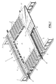
- the concrete floor structure of the type with collaborative bins 1, generally denoted by 1 in FIG. 1, is supported on two transverse end supports 2 consisting of beams, or more generally of all supporting structures of a building, and for example, load-bearing walls.
- the floor comprises a hopper 3 which is an opening of significant size, generally greater than 50cm by 50cm, and intended, for example, to lead a staircase.
- This concrete floor structure type cooperating tanks 1 consists of a plurality of ribbed self-supporting tanks 4 extending between the transverse end support beams 2 on which they rest at their ends. These bins are self-carrying bins known in themselves whose ribs are generally shaped omega.
- bins are arranged on both sides of the hopper 3.
- the concrete floor structure of the type cooperating tanks 1 also comprises reinforcement means generally marked by 5, surrounding the hopper 3 and ensuring the reinforcement of the floor around the hopper.
- These reinforcing elements 5 comprise two longitudinal crosspieces 6 extending over the entire length of the floor and bearing on the two transverse end support beams 2.
- the reinforcing means 5 also comprises two transverse headers 7, resting on the longitudinal crosspieces 6.
- the trimmers 7 are support means for ribbed self-carrying troughs 4 'of shorter length than the troughs 4 arranged on either side of the hopper, and which extend between on the one hand a beam of end support 2 and on the other hand a trimmer 7 so as to close the floor areas that lie between the end support beams and the trimmers.
- the floor structure also includes reinforcement reinforcing concrete 8 arranged in longitudinal ribs ribbed self-supporting tanks located in the vicinity of the longitudinal sleepers 6.
- These reinforcing reinforcements concrete 8 are intended to create in the vicinity of longitudinal sleepers a reinforced concrete beam structure.
- the structure of the concrete floor also comprises a wire mesh 9 extending over the entire surface and intended to provide a reinforcement of the surface of the concrete slab.
- the structure as just described is filled with concrete so as to form a slab 10 on which can be cast a yoke 11.
- the reinforcements 8 arranged in the ribs of the self-supporting tanks, parallel to longitudinal crosspieces, have ends which project beyond the floor so that they may be connected possibly to the reinforcements of the end support structures of the floor.
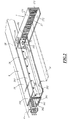
- Each longitudinal cross member consists of a main box 16 extending over the entire length of the floor and two secondary boxes 26 extending between the transverse end supports 2 and the headers 7.
- the longitudinal cross-member 6 consists of a main casing 16 of U-shaped section and comprising a vertical core 161, which is also the core of the cross-member, a lower horizontal flange. 162 extending opposite the hopper, on which are supported ribbed self-supporting tanks 4 extending over the entire length of the floor and a horizontal wing upper 163 also extending in a direction opposite to the hopper.
- This first box may consist of either a single sheet steel bent or profiled thickness between 1 and 4mm, or, as shown in the figure consisting of several nested structures each consisting of a thick sheet less than 4mm, so as to obtain a cross-member of significant thickness while being compatible with simple manufacture by folding or profiling.
- the longitudinal cross member 6 also comprises a U-shaped secondary casing 26 comprising a vertical core 261 contiguous to the vertical core 161 of the main casing 16, a lower horizontal wing 262 oriented in the direction of the hopper and an upper horizontal wing 263. also oriented towards the hopper.
- the vertical core 261 of the secondary caisson 26 is of a height slightly less than the height of the vertical core 161 of the main caisson 16.
- the two caissons are made integral by a plurality of self-drilling screws 60.
- the trunk 7 is also constituted by a U-shaped box having a vertical core 171 and two lower horizontal wings 172 and 173 extending in the direction opposite to the hopper.
- the height of the vertical core 171 of the casing 17 constituting the headpiece 7 is of identical height to the height of the vertical core 161 of the main casing 16 of the longitudinal cross member 6.
- the differences in height between the vertical core 261 of the secondary box and the vertical core 171 of the box 17 constituting the trimmer are adapted so that the box 17 comes to fit on the end 26 'of the secondary box 26 of the crossbar 6
- the trimmer 7 is in vertical support on the crossbar 6.
- the trimmer 7, arranged perpendicularly to the longitudinal cross member 6 is held in position on this cross member by means of a bracket 18 comprising a flange 181 and a flange 182 fixed respectively on the vertical core 171 of the header and the vertical web of the cross member 6, by via self-drilling screws 71 and 72 respectively.
- the ribbed self-supporting tank is fixed on the horizontal flange 162 by means of costing screws.
- the ribbed self-supporting tank 4 'disposed between the transverse end support beams and the headers adjacent to the crossmember 6 bears on the lower flange 262 of the secondary box 261 of the longitudinal cross member 6, on which it is fixed by costuring screws, and also on the lower flange 172 of the caper 7 on which it rests at one of the ends, and on which it is fixed by costing screw.
- the bins that extend along the other cross rests in the same way on the lower wings of the crossbar or the trimmer.
- the heights of the vertical webs 161 and 171, on the one hand, of the main box of the longitudinal cross member and, on the other hand, of the trimmer, are equal to the thickness of the concrete floor so that the reinforcing elements constitute formwork elements. around the hopper that delimit the concrete around this hopper and stop the concrete when it is poured to make the slab. In addition, the portion of these souls which is located around the hopper accurately defines the hopper.
- the reinforcing elements which have just been described consist of U-section boxes which are assembled. But other embodiments are possible.
- the U-shaped boxes can be replaced by L-section boxes having only a vertical core and a lower horizontal flange.
- the horizontal upper wing is not necessarily essential to obtain a good delimitation of the hoppers in the concrete floor.
- the box that constitutes the trimmer must be arranged so that its lower flange bears on the lower flange of the secondary box which is the longitudinal cross.
- connecting means between the longitudinal cross member and the treader may be of any type and are not necessarily brackets.
- the boxes which consist of reinforcing elements of the floor around the hopper, are metal boxes obtained by folding or profiling of metal sheets with a thickness between 1 and 4mm. This thickness is limited so as to allow folding and / or profiling under satisfactory conditions to be carried out near a site.
- reinforcing elements having greater mechanical properties than those which can be obtained with sheets up to 4 mm thick.
- These reinforcing elements can be made of bare steel or galvanized steel, so that they can be protected against corrosion.
- the hopper 100 is disposed in the central part of the floor and is delimited by two longitudinal crosspieces 103 and 104 resting on transverse end supports 101 and 102, and by two trimmers 105 and 106 bearing each on longitudinal rails 103 and 104.
- each longitudinal cross member 103, 104 consists of a main box 113, 114 respectively, and two secondary boxes 123, 123 'and 124, 124' respectively.
- the hopper 200 is disposed against one of the transverse end supports 201 of the floor.
- the floor rests on two transverse end supports 201, 202, and the hopper 200 is delimited on the one hand by one of the transverse end support 201 of the floor and by two longitudinal struts 203 and 204 which each support each other. on the two transverse end supports 201 and 202 of the floor, and a single treadle 205 resting on the two longitudinal struts.
- each longitudinal cross member 203, 204 consists of a main box 213 and 214, respectively, and a single secondary box 223 and 224 respectively.
- the hopper 300 is disposed at a distance from each of the transverse end supports of the floor, but is delimited laterally on one side by a longitudinal support 304 of the floor.
- the hopper 300 is delimited on the one hand by a longitudinal support 304 of the floor, by a longitudinal cross member 303 which bears on the two transverse end supports 301 and 302 of the floor and two trimmers 305 and 306 which rest on the one hand on the longitudinal cross member 303 and on the other hand on the longitudinal support 304 of the floor.
- the cross member 303 consists of a main box 313 and two secondary boxes 323 and 323 '.
- the floor rests on three supports, two transverse end supports 401 and 402 and a longitudinal support 404, and the hopper 400 is disposed in a corner delimited by one of the transverse end supports 401. , and by the longitudinal support 404.
- the hopper is further delimited by a single longitudinal cross member 403 which rests on the two transverse end supports 401 and 402, and by a trimmer 405 which bears on the one hand on the longitudinal cross member 403 and on the other part on the longitudinal support 404 of the floor.
- the cross member 413 consists of a single main box 413 and a single secondary box 423.
- a longitudinal cross member has only one main box, but depending on whether the structure provides for a single header or two headers, each longitudinal cross member has one or two secondary boxes.
- the floor comprises a single hopper delimited by two longitudinal crosspieces.
- the distances between the two transverse end supports of the floor are sufficient so that one can have between these two supports several hoppers arranged between two longitudinal crosspieces, and each delimited by a couple of trimmer .
- the truss elements incorporated in the thickness of the floor can be prepared as kits that can be made available to contractors to achieve as much as necessary. hoppers he wants to get.
- kits consist of main boxes for making longitudinal sleepers, secondary boxes for completing the longitudinal sleepers, boxes for making the trimmers, brackets or more generally means for connecting the headers with the longitudinal struts, and and finally, self-drilling screws for assembling the different components of the frame.
- the different components of the boxes can be cut to length by the user to adapt to each particular case.
- boxes can be either caissons consisting of a single sheet, or boxes consisting of several nestable elementary boxes that can be either nested directly before provision to the user, or that can be made available to the user. user in the form of a series of casings that can be nested.
- kits which have just been described in general, can be presented in different forms to be adapted to the four embodiments described above.
- the kits may include one or two sets for making longitudinal sleepers, and one or two sets for making trimmers.
- Longitudinal sleepers have standard lengths that are equal to the standard lengths of ribbed self-supporting bins. If there are several standard lengths of ribbed self-supporting tanks, kits corresponding to each of the standard lengths of ribbed self-supporting tanks can be envisaged.
- the user begins by preparing one or two longitudinal cross members according to the disposition of the hopper he wishes to achieve.
- the user cuts second boxes to suitable lengths and fixed the second boxes on the first or boxes so as to form one or two sleepers having a geometry adapted to the hopper he wishes to achieve.
- the user sets up the ribbed trays on both sides of the side of the hopper, then sets place the sleepers or rails that will delimit the hopper and will ensure the support of the whole.
- the user then sets up the ribbed trays corresponding to the floor portions disposed between the sleepers.
- These ribbed tanks have lengths less than the lengths of the ribbed trays that extend between the two lateral end supports of the floor.
- the user proceeds as is known to those skilled in the art, for example by providing temporary support tanks.
- the user sets up the one or more headers that he fixes through the fastening brackets on the longitudinal crosspieces.
- the user arranges them in such a way that the ribbed trays corresponding to the floor portions between the struts bear against the lower wing of the trimmers.
- the user then checks the squareness of the assembly and fixes the cross members on the transverse end supports and fixes the different bins on the sleepers and on the headers with the aid of costing screws.
- the user puts in place in the ribs adjacent to the longitudinal sleepers additional reinforcements which are intended to make concrete beams supporting the floor.
- additional reinforcements which are intended to make concrete beams supporting the floor.
- the user may either not provide additional reinforcement in the ribs self-carrier vane racks, or provide a single frame on each side of the hopper, or possibly provide reinforcements in several adjacent ribs.
- the presence or absence as well as the importance of reinforcement, as well as the thicknesses of the reinforcing elements are chosen by the skilled person according to the indications given by the calculation note relating to the work in question.
- the reinforcing elements consist of U-shaped boxes, but the person skilled in the art understands that he will be able to use profiles of different shapes, for example in L, provided that the functions beam, support ribs and binding are insured.
- fasteners by self-drilling screws may be replaced by any suitable fastening means that the skilled person will choose.
Landscapes
- Engineering & Computer Science (AREA)
- Architecture (AREA)
- Physics & Mathematics (AREA)
- Electromagnetism (AREA)
- Civil Engineering (AREA)
- Structural Engineering (AREA)
- Forms Removed On Construction Sites Or Auxiliary Members Thereof (AREA)
- On-Site Construction Work That Accompanies The Preparation And Application Of Concrete (AREA)
- Reinforcement Elements For Buildings (AREA)
- Joining Of Building Structures In Genera (AREA)
Priority Applications (5)
| Application Number | Priority Date | Filing Date | Title |
|---|---|---|---|
| ES06290848T ES2375996T3 (es) | 2006-05-24 | 2006-05-24 | Piso de hormigón, del tipo de moldes colaborantes que comprende una caja de medios de refuerzo para la realización de la caja. |
| AT06290848T ATE529582T1 (de) | 2006-05-24 | 2006-05-24 | Betondecke mit zusammenwirkenden schalungsplatten mit einer öffnung und bausatz um diese öffnung herzustellen |
| PT06290848T PT1860251E (pt) | 2006-05-24 | 2006-05-24 | Placa de betão do tipo tanques colaborantes compreendendo um vão e kit para a realização do vão |
| PL06290848T PL1860251T3 (pl) | 2006-05-24 | 2006-05-24 | Strop betonowy typu ze współpracującymi płytami, mający prześwit i zestaw do wykonywania prześwitu |
| EP06290848A EP1860251B1 (de) | 2006-05-24 | 2006-05-24 | Betondecke mit zusammenwirkenden Schalungsplatten mit einer Öffnung und Bausatz um diese Öffnung herzustellen |
Applications Claiming Priority (1)
| Application Number | Priority Date | Filing Date | Title |
|---|---|---|---|
| EP06290848A EP1860251B1 (de) | 2006-05-24 | 2006-05-24 | Betondecke mit zusammenwirkenden Schalungsplatten mit einer Öffnung und Bausatz um diese Öffnung herzustellen |
Publications (2)
| Publication Number | Publication Date |
|---|---|
| EP1860251A1 true EP1860251A1 (de) | 2007-11-28 |
| EP1860251B1 EP1860251B1 (de) | 2011-10-19 |
Family
ID=37564180
Family Applications (1)
| Application Number | Title | Priority Date | Filing Date |
|---|---|---|---|
| EP06290848A Active EP1860251B1 (de) | 2006-05-24 | 2006-05-24 | Betondecke mit zusammenwirkenden Schalungsplatten mit einer Öffnung und Bausatz um diese Öffnung herzustellen |
Country Status (5)
| Country | Link |
|---|---|
| EP (1) | EP1860251B1 (de) |
| AT (1) | ATE529582T1 (de) |
| ES (1) | ES2375996T3 (de) |
| PL (1) | PL1860251T3 (de) |
| PT (1) | PT1860251E (de) |
Cited By (4)
| Publication number | Priority date | Publication date | Assignee | Title |
|---|---|---|---|---|
| EP2304121A4 (de) * | 2008-06-13 | 2013-11-27 | Bluescope Steel Ltd | Plattenanordnung, verbundplatte und komponenten zur verwendung damit |
| CN114934621A (zh) * | 2022-07-21 | 2022-08-23 | 中国船舶重工集团国际工程有限公司 | 一种用于箱板装配式建筑中的组合楼盖及其安装方法 |
| WO2023170375A1 (en) | 2022-03-08 | 2023-09-14 | MCP Group Limited | Riser assembly |
| WO2024170878A1 (en) | 2023-02-13 | 2024-08-22 | MCP Group Limited | Riser assembly |
Citations (3)
| Publication number | Priority date | Publication date | Assignee | Title |
|---|---|---|---|---|
| GB2265640A (en) * | 1992-03-31 | 1993-10-06 | Halfen Fixing Systems Limited | Pour stop for concrete structure |
| US5941035A (en) * | 1997-09-03 | 1999-08-24 | Mega Building System Ltd. | Steel joist and concrete floor system |
| NL1020123C1 (nl) * | 2002-03-07 | 2003-09-12 | Bat Continental B V | Verloren randbekistingselementen en werkwijze voor het installeren van verankeringsorganen. |
-
2006
- 2006-05-24 ES ES06290848T patent/ES2375996T3/es active Active
- 2006-05-24 AT AT06290848T patent/ATE529582T1/de not_active IP Right Cessation
- 2006-05-24 PT PT06290848T patent/PT1860251E/pt unknown
- 2006-05-24 PL PL06290848T patent/PL1860251T3/pl unknown
- 2006-05-24 EP EP06290848A patent/EP1860251B1/de active Active
Patent Citations (3)
| Publication number | Priority date | Publication date | Assignee | Title |
|---|---|---|---|---|
| GB2265640A (en) * | 1992-03-31 | 1993-10-06 | Halfen Fixing Systems Limited | Pour stop for concrete structure |
| US5941035A (en) * | 1997-09-03 | 1999-08-24 | Mega Building System Ltd. | Steel joist and concrete floor system |
| NL1020123C1 (nl) * | 2002-03-07 | 2003-09-12 | Bat Continental B V | Verloren randbekistingselementen en werkwijze voor het installeren van verankeringsorganen. |
Cited By (4)
| Publication number | Priority date | Publication date | Assignee | Title |
|---|---|---|---|---|
| EP2304121A4 (de) * | 2008-06-13 | 2013-11-27 | Bluescope Steel Ltd | Plattenanordnung, verbundplatte und komponenten zur verwendung damit |
| WO2023170375A1 (en) | 2022-03-08 | 2023-09-14 | MCP Group Limited | Riser assembly |
| CN114934621A (zh) * | 2022-07-21 | 2022-08-23 | 中国船舶重工集团国际工程有限公司 | 一种用于箱板装配式建筑中的组合楼盖及其安装方法 |
| WO2024170878A1 (en) | 2023-02-13 | 2024-08-22 | MCP Group Limited | Riser assembly |
Also Published As
| Publication number | Publication date |
|---|---|
| ATE529582T1 (de) | 2011-11-15 |
| ES2375996T3 (es) | 2012-03-08 |
| EP1860251B1 (de) | 2011-10-19 |
| PL1860251T3 (pl) | 2012-03-30 |
| PT1860251E (pt) | 2011-12-19 |
Similar Documents
| Publication | Publication Date | Title |
|---|---|---|
| BE679420A (de) | ||
| EP1941104A1 (de) | Neue art von gebäude, verfahren und mittel zu seiner errichtung | |
| EP0285465B1 (de) | Bauelement, insbesondere Verkleidungselement mit integrierter Wärmedämmung | |
| FR2950638A1 (fr) | Systeme constructif pour batiments | |
| EP1860251B1 (de) | Betondecke mit zusammenwirkenden Schalungsplatten mit einer Öffnung und Bausatz um diese Öffnung herzustellen | |
| FR2560621A1 (fr) | Element nervure et dalle composee de tels elements ainsi que le procede de fabrication de ces elements et les moyens en vue de la mise en oeuvre de ce procede | |
| FR2922916A1 (fr) | Element modulaire prefabrique de plancher sec, procede de fabrication d'un tel element modulaire et plancher sec constitue d'une pluralite d'elements modulaires. | |
| EP0271400A1 (de) | Fassadeverkleidung mit ventilierter Luftschicht | |
| EP2844809B1 (de) | Schalung und entsprechender boden | |
| FR2913993A1 (fr) | Entrevous en matrice minerale, dispositif de plancher a entrevous et son procede de realisation | |
| EP4343079B1 (de) | Wandverbindungsbeschlag mit integrierter schalung | |
| EP0767282A1 (de) | Verbundmetallträger | |
| FR2938856A1 (fr) | Chapiteau prefabrique en beton, et procede de mise en oeuvre d'un tel chapiteau dans une ossature de plancher | |
| EP1380703B1 (de) | Wechselbauweise für aus Plattenelementen hergestellte Decken und dazu verwendete Wechselzusatzvorrichtung | |
| BE1005389A3 (fr) | Paroi mixte et tole profilee pour une telle paroi. | |
| FR2729411A3 (fr) | Dalle coffrante nervuree legere en beton arme pour plancher dalle-pleine et son procede de fabrication | |
| EP0440567A1 (de) | Einzelne und doppelte Träger und Pfosten, bestehend aus der Zusammensetzung von Z-Trägern, die insbesondere die Realisierung eines Rahmens oder einer Kniestütze für den Bau eines Gebäudes erlauben | |
| FR2956139A1 (fr) | Element de coffrage pour la construction d'une poutrelle | |
| FR2474083A1 (fr) | Poutrelle d'armature prefabriquee, notamment en vue de la realisation de planchers pour renovation | |
| FR2768758A1 (fr) | Elements de toiture isolants, toiture et son procede de construction a partir de tels elements | |
| EP4632163A1 (de) | Rahmenlamelle, bausatz und verfahren zur vereinfachten montage einer fassadenverkleidung zur isolierung eines gebäudes | |
| FR2530705A1 (fr) | Elements de construction pour la prefabrication notamment de planchers | |
| FR2756306A1 (fr) | Panneau d'isolation de toitures a fermettes | |
| FR3151342A1 (fr) | Bloc de construction et procédé d’obtention d’un tel bloc | |
| WO2013045660A1 (fr) | Element de poutre prefabrique, adapte pour former un element constitutif d'une travee de pont metallique et procede de construction modulaire d'une telle travee |
Legal Events
| Date | Code | Title | Description |
|---|---|---|---|
| PUAI | Public reference made under article 153(3) epc to a published international application that has entered the european phase |
Free format text: ORIGINAL CODE: 0009012 |
|
| AK | Designated contracting states |
Kind code of ref document: A1 Designated state(s): AT BE BG CH CY CZ DE DK EE ES FI FR GB GR HU IE IS IT LI LT LU LV MC NL PL PT RO SE SI SK TR |
|
| AX | Request for extension of the european patent |
Extension state: AL BA HR MK YU |
|
| 17P | Request for examination filed |
Effective date: 20080307 |
|
| AKX | Designation fees paid |
Designated state(s): AT BE BG CH CY CZ DE DK EE ES FI FR GB GR HU IE IS IT LI LT LU LV MC NL PL PT RO SE SI SK TR |
|
| AXX | Extension fees paid |
Extension state: AL Payment date: 20080307 Extension state: YU Payment date: 20080307 Extension state: MK Payment date: 20080307 Extension state: BA Payment date: 20080307 Extension state: HR Payment date: 20080307 |
|
| 17Q | First examination report despatched |
Effective date: 20101222 |
|
| GRAP | Despatch of communication of intention to grant a patent |
Free format text: ORIGINAL CODE: EPIDOSNIGR1 |
|
| GRAS | Grant fee paid |
Free format text: ORIGINAL CODE: EPIDOSNIGR3 |
|
| RAP1 | Party data changed (applicant data changed or rights of an application transferred) |
Owner name: ARCELORMITTAL CONSTRUCTION FRANCE |
|
| GRAA | (expected) grant |
Free format text: ORIGINAL CODE: 0009210 |
|
| AK | Designated contracting states |
Kind code of ref document: B1 Designated state(s): AT BE BG CH CY CZ DE DK EE ES FI FR GB GR HU IE IS IT LI LT LU LV MC NL PL PT RO SE SI SK TR |
|
| AX | Request for extension of the european patent |
Extension state: AL BA HR MK YU |
|
| REG | Reference to a national code |
Ref country code: GB Ref legal event code: FG4D Free format text: NOT ENGLISH |
|
| REG | Reference to a national code |
Ref country code: CH Ref legal event code: EP |
|
| REG | Reference to a national code |
Ref country code: IE Ref legal event code: FG4D |
|
| REG | Reference to a national code |
Ref country code: PT Ref legal event code: SC4A Free format text: AVAILABILITY OF NATIONAL TRANSLATION Effective date: 20111129 |
|
| REG | Reference to a national code |
Ref country code: NL Ref legal event code: T3 |
|
| REG | Reference to a national code |
Ref country code: DE Ref legal event code: R096 Ref document number: 602006025188 Country of ref document: DE Effective date: 20111222 |
|
| REG | Reference to a national code |
Ref country code: ES Ref legal event code: FG2A Ref document number: 2375996 Country of ref document: ES Kind code of ref document: T3 Effective date: 20120308 |
|
| LTIE | Lt: invalidation of european patent or patent extension |
Effective date: 20111019 |
|
| REG | Reference to a national code |
Ref country code: PL Ref legal event code: T3 |
|
| REG | Reference to a national code |
Ref country code: AT Ref legal event code: MK05 Ref document number: 529582 Country of ref document: AT Kind code of ref document: T Effective date: 20111019 |
|
| PG25 | Lapsed in a contracting state [announced via postgrant information from national office to epo] |
Ref country code: IS Free format text: LAPSE BECAUSE OF FAILURE TO SUBMIT A TRANSLATION OF THE DESCRIPTION OR TO PAY THE FEE WITHIN THE PRESCRIBED TIME-LIMIT Effective date: 20120219 Ref country code: LT Free format text: LAPSE BECAUSE OF FAILURE TO SUBMIT A TRANSLATION OF THE DESCRIPTION OR TO PAY THE FEE WITHIN THE PRESCRIBED TIME-LIMIT Effective date: 20111019 |
|
| REG | Reference to a national code |
Ref country code: IE Ref legal event code: FD4D |
|
| PG25 | Lapsed in a contracting state [announced via postgrant information from national office to epo] |
Ref country code: SE Free format text: LAPSE BECAUSE OF FAILURE TO SUBMIT A TRANSLATION OF THE DESCRIPTION OR TO PAY THE FEE WITHIN THE PRESCRIBED TIME-LIMIT Effective date: 20111019 Ref country code: SI Free format text: LAPSE BECAUSE OF FAILURE TO SUBMIT A TRANSLATION OF THE DESCRIPTION OR TO PAY THE FEE WITHIN THE PRESCRIBED TIME-LIMIT Effective date: 20111019 Ref country code: GR Free format text: LAPSE BECAUSE OF FAILURE TO SUBMIT A TRANSLATION OF THE DESCRIPTION OR TO PAY THE FEE WITHIN THE PRESCRIBED TIME-LIMIT Effective date: 20120120 Ref country code: LV Free format text: LAPSE BECAUSE OF FAILURE TO SUBMIT A TRANSLATION OF THE DESCRIPTION OR TO PAY THE FEE WITHIN THE PRESCRIBED TIME-LIMIT Effective date: 20111019 |
|
| PG25 | Lapsed in a contracting state [announced via postgrant information from national office to epo] |
Ref country code: CY Free format text: LAPSE BECAUSE OF FAILURE TO SUBMIT A TRANSLATION OF THE DESCRIPTION OR TO PAY THE FEE WITHIN THE PRESCRIBED TIME-LIMIT Effective date: 20111019 |
|
| PG25 | Lapsed in a contracting state [announced via postgrant information from national office to epo] |
Ref country code: DK Free format text: LAPSE BECAUSE OF FAILURE TO SUBMIT A TRANSLATION OF THE DESCRIPTION OR TO PAY THE FEE WITHIN THE PRESCRIBED TIME-LIMIT Effective date: 20111019 Ref country code: CZ Free format text: LAPSE BECAUSE OF FAILURE TO SUBMIT A TRANSLATION OF THE DESCRIPTION OR TO PAY THE FEE WITHIN THE PRESCRIBED TIME-LIMIT Effective date: 20111019 Ref country code: SK Free format text: LAPSE BECAUSE OF FAILURE TO SUBMIT A TRANSLATION OF THE DESCRIPTION OR TO PAY THE FEE WITHIN THE PRESCRIBED TIME-LIMIT Effective date: 20111019 Ref country code: BG Free format text: LAPSE BECAUSE OF FAILURE TO SUBMIT A TRANSLATION OF THE DESCRIPTION OR TO PAY THE FEE WITHIN THE PRESCRIBED TIME-LIMIT Effective date: 20120119 Ref country code: IE Free format text: LAPSE BECAUSE OF FAILURE TO SUBMIT A TRANSLATION OF THE DESCRIPTION OR TO PAY THE FEE WITHIN THE PRESCRIBED TIME-LIMIT Effective date: 20111019 Ref country code: EE Free format text: LAPSE BECAUSE OF FAILURE TO SUBMIT A TRANSLATION OF THE DESCRIPTION OR TO PAY THE FEE WITHIN THE PRESCRIBED TIME-LIMIT Effective date: 20111019 |
|
| PLBE | No opposition filed within time limit |
Free format text: ORIGINAL CODE: 0009261 |
|
| STAA | Information on the status of an ep patent application or granted ep patent |
Free format text: STATUS: NO OPPOSITION FILED WITHIN TIME LIMIT |
|
| PG25 | Lapsed in a contracting state [announced via postgrant information from national office to epo] |
Ref country code: RO Free format text: LAPSE BECAUSE OF FAILURE TO SUBMIT A TRANSLATION OF THE DESCRIPTION OR TO PAY THE FEE WITHIN THE PRESCRIBED TIME-LIMIT Effective date: 20111019 Ref country code: IT Free format text: LAPSE BECAUSE OF FAILURE TO SUBMIT A TRANSLATION OF THE DESCRIPTION OR TO PAY THE FEE WITHIN THE PRESCRIBED TIME-LIMIT Effective date: 20111019 |
|
| 26N | No opposition filed |
Effective date: 20120720 |
|
| REG | Reference to a national code |
Ref country code: DE Ref legal event code: R097 Ref document number: 602006025188 Country of ref document: DE Effective date: 20120720 |
|
| BERE | Be: lapsed |
Owner name: ARCELORMITTAL CONSTRUCTION FRANCE Effective date: 20120531 |
|
| REG | Reference to a national code |
Ref country code: NL Ref legal event code: V1 Effective date: 20121201 |
|
| PG25 | Lapsed in a contracting state [announced via postgrant information from national office to epo] |
Ref country code: MC Free format text: LAPSE BECAUSE OF NON-PAYMENT OF DUE FEES Effective date: 20120531 |
|
| REG | Reference to a national code |
Ref country code: CH Ref legal event code: PL |
|
| GBPC | Gb: european patent ceased through non-payment of renewal fee |
Effective date: 20120524 |
|
| PG25 | Lapsed in a contracting state [announced via postgrant information from national office to epo] |
Ref country code: LI Free format text: LAPSE BECAUSE OF NON-PAYMENT OF DUE FEES Effective date: 20120531 Ref country code: CH Free format text: LAPSE BECAUSE OF NON-PAYMENT OF DUE FEES Effective date: 20120531 Ref country code: AT Free format text: LAPSE BECAUSE OF FAILURE TO SUBMIT A TRANSLATION OF THE DESCRIPTION OR TO PAY THE FEE WITHIN THE PRESCRIBED TIME-LIMIT Effective date: 20111019 |
|
| PG25 | Lapsed in a contracting state [announced via postgrant information from national office to epo] |
Ref country code: BE Free format text: LAPSE BECAUSE OF NON-PAYMENT OF DUE FEES Effective date: 20120531 |
|
| REG | Reference to a national code |
Ref country code: FR Ref legal event code: ST Effective date: 20130131 |
|
| REG | Reference to a national code |
Ref country code: PT Ref legal event code: MM4A Free format text: LAPSE DUE TO NON-PAYMENT OF FEES Effective date: 20130225 |
|
| REG | Reference to a national code |
Ref country code: DE Ref legal event code: R119 Ref document number: 602006025188 Country of ref document: DE Effective date: 20121201 |
|
| PG25 | Lapsed in a contracting state [announced via postgrant information from national office to epo] |
Ref country code: NL Free format text: LAPSE BECAUSE OF NON-PAYMENT OF DUE FEES Effective date: 20121201 |
|
| PG25 | Lapsed in a contracting state [announced via postgrant information from national office to epo] |
Ref country code: FR Free format text: LAPSE BECAUSE OF NON-PAYMENT OF DUE FEES Effective date: 20120531 Ref country code: GB Free format text: LAPSE BECAUSE OF NON-PAYMENT OF DUE FEES Effective date: 20120524 |
|
| PG25 | Lapsed in a contracting state [announced via postgrant information from national office to epo] |
Ref country code: PT Free format text: LAPSE BECAUSE OF NON-PAYMENT OF DUE FEES Effective date: 20130225 |
|
| PG25 | Lapsed in a contracting state [announced via postgrant information from national office to epo] |
Ref country code: FI Free format text: LAPSE BECAUSE OF FAILURE TO SUBMIT A TRANSLATION OF THE DESCRIPTION OR TO PAY THE FEE WITHIN THE PRESCRIBED TIME-LIMIT Effective date: 20111019 Ref country code: DE Free format text: LAPSE BECAUSE OF NON-PAYMENT OF DUE FEES Effective date: 20121201 |
|
| REG | Reference to a national code |
Ref country code: ES Ref legal event code: FD2A Effective date: 20130820 |
|
| PG25 | Lapsed in a contracting state [announced via postgrant information from national office to epo] |
Ref country code: PL Free format text: LAPSE BECAUSE OF NON-PAYMENT OF DUE FEES Effective date: 20120524 |
|
| REG | Reference to a national code |
Ref country code: PL Ref legal event code: LAPE |
|
| PG25 | Lapsed in a contracting state [announced via postgrant information from national office to epo] |
Ref country code: ES Free format text: LAPSE BECAUSE OF NON-PAYMENT OF DUE FEES Effective date: 20120525 |
|
| PG25 | Lapsed in a contracting state [announced via postgrant information from national office to epo] |
Ref country code: TR Free format text: LAPSE BECAUSE OF FAILURE TO SUBMIT A TRANSLATION OF THE DESCRIPTION OR TO PAY THE FEE WITHIN THE PRESCRIBED TIME-LIMIT Effective date: 20111019 |
|
| PG25 | Lapsed in a contracting state [announced via postgrant information from national office to epo] |
Ref country code: LU Free format text: LAPSE BECAUSE OF NON-PAYMENT OF DUE FEES Effective date: 20120524 |
|
| PG25 | Lapsed in a contracting state [announced via postgrant information from national office to epo] |
Ref country code: HU Free format text: LAPSE BECAUSE OF FAILURE TO SUBMIT A TRANSLATION OF THE DESCRIPTION OR TO PAY THE FEE WITHIN THE PRESCRIBED TIME-LIMIT Effective date: 20060524 |