EP2844809B1 - Schalung und entsprechender boden - Google Patents
Schalung und entsprechender boden Download PDFInfo
- Publication number
- EP2844809B1 EP2844809B1 EP13727641.6A EP13727641A EP2844809B1 EP 2844809 B1 EP2844809 B1 EP 2844809B1 EP 13727641 A EP13727641 A EP 13727641A EP 2844809 B1 EP2844809 B1 EP 2844809B1
- Authority
- EP
- European Patent Office
- Prior art keywords
- formwork
- self
- profile
- supporting
- extending
- Prior art date
- Legal status (The legal status is an assumption and is not a legal conclusion. Google has not performed a legal analysis and makes no representation as to the accuracy of the status listed.)
- Not-in-force
Links
- 238000009415 formwork Methods 0.000 title claims description 65
- 125000006850 spacer group Chemical group 0.000 claims description 52
- 230000006835 compression Effects 0.000 claims description 26
- 238000007906 compression Methods 0.000 claims description 26
- 239000002131 composite material Substances 0.000 claims description 14
- 239000003351 stiffener Substances 0.000 claims description 12
- 238000004519 manufacturing process Methods 0.000 claims description 10
- 230000003014 reinforcing effect Effects 0.000 claims description 8
- 239000007788 liquid Substances 0.000 claims description 5
- 238000000034 method Methods 0.000 claims 2
- 244000245420 ail Species 0.000 description 12
- 238000010276 construction Methods 0.000 description 8
- 239000002184 metal Substances 0.000 description 7
- 229910052751 metal Inorganic materials 0.000 description 7
- 238000004826 seaming Methods 0.000 description 5
- 229910000831 Steel Inorganic materials 0.000 description 3
- 239000000654 additive Substances 0.000 description 3
- 230000000996 additive effect Effects 0.000 description 3
- 239000010959 steel Substances 0.000 description 3
- 238000004873 anchoring Methods 0.000 description 2
- 239000000470 constituent Substances 0.000 description 2
- 238000009826 distribution Methods 0.000 description 2
- 238000005304 joining Methods 0.000 description 2
- 230000002787 reinforcement Effects 0.000 description 2
- 240000008042 Zea mays Species 0.000 description 1
- 229910001297 Zn alloy Inorganic materials 0.000 description 1
- 230000003416 augmentation Effects 0.000 description 1
- 238000005452 bending Methods 0.000 description 1
- 230000015572 biosynthetic process Effects 0.000 description 1
- 238000005266 casting Methods 0.000 description 1
- 239000011248 coating agent Substances 0.000 description 1
- 238000000576 coating method Methods 0.000 description 1
- 238000005260 corrosion Methods 0.000 description 1
- 230000007797 corrosion Effects 0.000 description 1
- 238000005336 cracking Methods 0.000 description 1
- 230000000694 effects Effects 0.000 description 1
- 238000009408 flooring Methods 0.000 description 1
- 239000012530 fluid Substances 0.000 description 1
- 238000009413 insulation Methods 0.000 description 1
- 230000002452 interceptive effect Effects 0.000 description 1
- 239000000463 material Substances 0.000 description 1
- 239000003973 paint Substances 0.000 description 1
- 238000004088 simulation Methods 0.000 description 1
Images

Classifications
-
- E—FIXED CONSTRUCTIONS
- E04—BUILDING
- E04B—GENERAL BUILDING CONSTRUCTIONS; WALLS, e.g. PARTITIONS; ROOFS; FLOORS; CEILINGS; INSULATION OR OTHER PROTECTION OF BUILDINGS
- E04B5/00—Floors; Floor construction with regard to insulation; Connections specially adapted therefor
- E04B5/16—Load-carrying floor structures wholly or partly cast or similarly formed in situ
- E04B5/32—Floor structures wholly cast in situ with or without form units or reinforcements
- E04B5/36—Floor structures wholly cast in situ with or without form units or reinforcements with form units as part of the floor
- E04B5/38—Floor structures wholly cast in situ with or without form units or reinforcements with form units as part of the floor with slab-shaped form units acting simultaneously as reinforcement; Form slabs with reinforcements extending laterally outside the element
- E04B5/40—Floor structures wholly cast in situ with or without form units or reinforcements with form units as part of the floor with slab-shaped form units acting simultaneously as reinforcement; Form slabs with reinforcements extending laterally outside the element with metal form-slabs
Definitions
- the present invention relates to a formwork for the construction of mixed steel-concrete floors obtained by casting a concrete slab on the formwork.
- the floor obtained can be of 3 different types: with lost formwork, additive or collaborating.
- loose form flooring it is meant that only concrete contributes to the mechanical strength of the floor.
- additive floor it is meant that the mechanical strength of the floor is the addition of the respective strengths of the formwork and concrete.
- collaborating floor means that the resistance of the floor is greater than the addition of the respective strengths of the formwork and concrete.
- the metal formwork must support the sum of the weight of concrete and its own weight without ruin or excessive deflection, and this is done or not with provisional struts arranged at regular intervals between them. retaining walls of the floor.
- the floor after the removal of any temporary struts and during the use phase of the floor, referred to as the mixed phase, the floor must not sag too much under normal conditions of use.
- the present invention aims to overcome the aforementioned problems by providing a formwork to minimize the amount of concrete necessary while maintaining a mechanical strength of the mixed floor sufficient to increase its range beyond 8 meters.
- the various components of the formwork are preferably made of metal such as bare steel or galvanized with a zinc alloy.
- the steel, galvanized or not will be covered with a layer of paint to better protect it from corrosion.
- At least one of the constituent elements of the formwork, and in particular the spacer profile, may however be made of plastic or any other material sufficiently resistant to the use for which the element is intended.
- the constituent sections of the formwork undergo bending forces such that the upper parts of the profiles are subjected to compression stresses and the lower parts of the profiles to tensile stresses, especially in the longitudinal direction. .
- the relative importance of the tensile and compression zones depends on different geometrical parameters such as the height of the cores, the thickness of the concrete layer, the length and width of the sections. Those skilled in the art can determine from these parameters what is the relative distribution of the areas subjected to traction and areas subject to compression. As a general rule, the boundary between the tensile zone and the compression zone is around half the height of the lateral web of the profile.
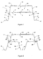
- the formwork 1 comprises a self-supporting profile 2.
- self-supporting profile is meant a shaped sheet so that the simple rigidity of this form ensures its stability and allows its implementation on the structure of the building under construction. through its ends.
- the shapes that can take this self-supporting profile are known per se.
- the self-supporting profile comprises at least one horizontal upper central zone 3 extending in the longitudinal direction of the self-supporting profile, two lateral webs 4 and 4 'extending the upper central zone 3 on either side thereof and towards the bottom and at least two horizontal lower flanges 5 and 5 'extending the lateral webs.
- the upper central zone 3 furthermore comprises two longitudinal ribs 6 and 6 'separated by a transverse notch 7. This conformation increases the rigidity of the upper central zone 3 and thus makes possible the circulation of the workers on this area.
- the lateral webs 4 and 4 ' are inclined, extending towards the bottom and towards the outside of the upper central area. Alternatively, they can extend vertically or inward, depending on the desired rigidity of the self-supporting profile.
- Each lateral core of this example also comprises a longitudinal stiffener 8, 8 'consisting of two folds forming a slight recess in the part of the lateral core subjected to compression forces during the mixed phase.
- This longitudinal stiffener improves the mechanical behavior of the self-supporting profile and, on the other hand, promotes the establishment of a spacer profile as will be seen later.
- the lateral webs 4 and 4 ' may have concrete anchoring zones such as bosses or notches located in the part of the lateral web subjected to tensile forces.
- the lower flanges 5 and 5 ' have a raised edge 9, 9' which acts as a stiffener and facilitates the implementation of the formwork in particular by making the junctions between two adjacent self-supporting profiles more sealed to concrete liquid.
- the self-supporting profile has a height of between 150 and 300 mm, the example of the figure 1 having been made with a freestanding profile of 220 mm high.
- the formwork 1 comprises a spacer profile 10.
- the latter comprises a horizontal upper plate 11 extending in the longitudinal direction of the spacer profile and two lateral wings 12, 12 'extending the upper plate 11 on either side from it and towards the bottom.
- the upper plate 11 further comprises a transverse strike 13. This conformation increases the rigidity of the upper plate 11 and thus makes possible the movement of workers on this surface.
- the upper plate 11 may have longitudinal ribs or concrete anchoring areas such as bosses or notches.
- each side wing of this example is flat and comprises, at its end, a raised edge 14, 14 'which acts as a stiffener and facilitates the establishment of the spacer profile 10 on the self-supporting profile 2.
- the spacer profile has a height of between 80 and 250 mm, the example of the figure 1 having been made with a spacer profile of 150 mm high.
- the raised edge 14 (respectively 14 ') of the lateral flange of the spacer profile is fitted on the self-supporting profile and bears on the longitudinal stiffener 8 (8' respectively) thereof.
- the two sections are secured preferably by seaming, preferably via fasteners 16, such as for example screws or rivets, evenly distributed along the length of the raised edge 14, 14 '.
- the number of fasteners is limited to shorten the floor's manufacturing time.
- the seam is then not sufficient for the spacer profile to participate in the mechanical strength of the entire mixed floor.
- the spacer profile is in this case to formwork lost.
- it is advantageous to improve the mechanical strength of the floor by multiplying the number of fasteners, which however lengthens the manufacturing time of the floor. A compromise is therefore to be found between the desired mechanical resistance of the floor and the time spent seaming the spacer profile to the self-supporting profile.
- the seaming can be done on site or alternatively in the factory before delivery of the formwork on site.
- the box 15 is left empty. Alternatively, it may be filled with thermal and / or acoustic insulation and / or accommodate the electrical networks and / or fluid networks of the building under construction.
- This second formwork 1 differs from the formwork illustrated in FIG. figure 1 mainly in that the self-supporting profile 2 comprises two upper central areas 3 and in that the spacer profile 10 covers them.
- the upper plate 11 of the spacer profile comprises a transverse detent 13 and longitudinal ribs 17, 17 'acting as stiffeners.
- the lateral wings 12, 12 ' are inclined, extending towards the bottom and towards the outside of the upper plate 11.
- Each lateral wing of this example comprises longitudinal stiffeners 18, 18' consisting of folds forming a slight recess in the lateral wing.
- the end of each lateral wing is formed of a recess 19, 19 'Z-shaped which acts as a stiffener and facilitates the establishment of the spacer profile 10 on the self-supporting profile 2.
- the recess 19 (respectively 19 ') of the end of the side wing abuts on the end 20 of the first upper central strip of the self-supporting profile 2 (respectively on the end 20' from the second upper central range).
- the two sections are secured by seaming, preferably via fasteners 16, such as for example screws or rivets, regularly distributed over the length of the recess 19, 19 '.
- the fitting mode of the spacer profile on the self-supporting profile via the recess 19, 19 ', as illustrated in FIG. figure 2 can be implemented in the example of the figure 1 instead of the mode of engagement through the raised edge 14, 14 'and vice versa.
- the spacer profile can take various forms. Its upper plate may for example have ribs such that several boxes 15 are formed between the spacer profile and the self-supporting profile.
- the composite steel-concrete floor is made by the juxtaposition of formwork 1 on the structure 21 of the building under construction as illustrated in FIG. figure 3 .
- the formwork 1 can be immediately adjacent to each other, as shown in FIG. figure 3 , or interposed between self-supporting profiles 2 not provided with spacer profile 10.
- Reinforcing reinforcing bars 22 are then disposed in wave recesses 23 formed by the lateral webs of two successive self-supporting profiles 2.
- Liquid concrete is then poured over the entire surface formed by the formwork 1 and any self-supporting profiles 2, so as to form a slab 24.
- the distance separating the top of the spacer profiles from the surface of the slab will be at least 20 mm in order to ensure the good compressive strength of the slab.
- distances of the order of 50 to 200 mm will be preferred to allow the coating of any anti-cracking reinforcement or to allow the structure which carries the composite floor to work mainly in traction or to increase the fire resistance. .
- the caissons 15 formed by the interlocking of the spacer profiles 10 on the self-supporting profiles 2 make it possible to minimize the quantity of concrete necessary for the formation of the slab. It is thus possible to make floors of greater length.
- the shape and dimensions of the boxes will be adjusted according to the circumstances in order to obtain the best compromise between the desired mechanical strength and range of the composite floor.
- the spacer profile may thus be of width less than the width of the upper central region of the self-supporting profile so that it covers only partially the upper central zone when it is arranged by the end of its lateral wings on the self-supporting profile. .
- Such a configuration may be suitable when one does not seek to greatly reduce the mixed floor.
- preference will be given to the configuration for which the spacer profile covers the entirety of at least one upper central range so that one side of the box is formed at least by the entire upper central range (except for the possible localized support of the recess 19, 19 'on the end 20, 20' of the upper central range).
- the ratio between the height of the spacer profile and the height of the self-supporting profile will preferably vary between 0.35 and 1.
- the combination of a freestanding profile height of between 150 and 300 mm and the ratio between 0.35 and 1 makes it possible to obtain a formwork presenting the best optimum in terms of inertia and lightening.
Landscapes
- Engineering & Computer Science (AREA)
- Architecture (AREA)
- Physics & Mathematics (AREA)
- Electromagnetism (AREA)
- Civil Engineering (AREA)
- Structural Engineering (AREA)
- Forms Removed On Construction Sites Or Auxiliary Members Thereof (AREA)
- Building Environments (AREA)
Claims (15)
- Schalung (1) für eine Stahlbetonverbunddecke, umfassend ein selbsttragendes Profil (2) mit mindestens einem oberen zentralen Bereich (3), Seitenstege (4, 4'), die den oberen zentralen Bereich auf beiden Seiten desselben und nach unten verlängern, und mindestens zwei untere Auflagen (5, 5'), die die Seitenstege verlängern,
wobei die Schalung dadurch gekennzeichnet ist, dass sie außerdem ein Abstandsprofil (10) mit mindestens einer oberen Platte (11) und zwei Seitenflügeln (12, 12') umfasst, die die obere Platte auf beiden Seiten derselben und nach unten verlängern,
wobei das Abstandsprofil mindestens durch das Ende der Seitenflügel auf dem oberen Teil des selbsttragenden Profils angeordnet ist, der dazu ausgelegt ist, in Kompression zu arbeiten, wobei die Grenze zwischen dem Teil, der ausgelegt ist, um in Kompression zu arbeiten, und dem Teil, der ausgelegt ist, um in Traktion zu arbeiten, in der Umgebung der Hälfte der Höhe des Seitenstegs des selbsttragenden Profils angeordnet ist, um mindestens teilweise den oberen zentralen Bereich abzudecken und so mindestens einen Kasten (15) zu bilden, der ermöglicht, die erforderliche Menge von Beton zu minimieren. - Schalung (1) nach Anspruch 1, wobei das Abstandsprofil (10) die Gesamtheit des oberen zentralen Bereichs (3) abdeckt.
- Schalung (10) nach einem beliebigen der vorhergehenden Ansprüche, wobei die Seitenstege (4, 4') hin zur Außenseite des oberen zentralen Bereichs (3) geneigt sind.
- Schalung (10) nach einem beliebigen der vorhergehenden Ansprüche, wobei jeder der Seitenstege (4, 4') eine längs gerichtetes Versteifungselement (8, 8') umfasst, das aus zwei Falten hergestellt ist, die eine Ausbuchtung des Seitenstegs bilden.
- Schalung (1) nach einem beliebigen der vorhergehenden Ansprüche, wobei die Seitenflügel (12, 12') auf die Außenseite der oberen Platte (11) geneigt sind.
- Schalung (1) nach einem beliebigen der vorhergehenden Ansprüche, wobei das Ende der Seitenflügel (12, 12') einen erhöhten Rand (14, 14') umfasst.
- Schalung (1) nach Anspruch 4 und 6, wobei der erhöhte Rand (14, 14') auf dem längs gerichteten Versteifungselement (8, 8') aufliegt, wobei das Abstandsprofil und das selbsttragende Profil durch Überlappung mit Hilfe von Fixierungen (16), die regelmäßig auf der Länge des erhöhten Rands (14, 14') verteilt sind, fest verbunden sind.
- Schalung (1) nach einem beliebigen der vorhergehenden Ansprüche 1 bis 5, wobei das Ende der Seitenflügel (12, 12') eine Ausbuchtung (19, 19') in Form eines "Z" umfasst.
- Schalung (1) nach Anspruch 8, wobei die Ausbuchtung (19, 19') auf Enden (20, 20') des oberen zentralen Bereichs aufliegt.
- Schalung (1) nach einem beliebigen der vorhergehenden Ansprüche, wobei das selbsttragende Profil (2) zwei obere zentrale Bereiche (3) umfasst.
- Schalung (1) nach Anspruch 10, wobei das selbsttragende Profil (10) die zwei oberen zentralen Bereiche (3) mindestens teilweise abdeckt.
- Verfahren zur Herstellung einer Schalung (1) für eine Stahlbetonverbunddecke, umfassend die folgenden Schritte, nach denen:- ein selbsttragendes Profil (2) mit mindestens einem oberen zentralen Bereich (3), Seitenstegen (4, 4'), die den oberen zentralen Bereich auf beiden Seiten desselben und nach unten verlängern, und mindestens zwei untere Auflagen (5, 5'), die die Seitenstege verlängern, bereitgestellt werden,- ein Abstandsprofil (10) mit mindestens einer oberen Platte (11) und zwei Seitenflügeln (12, 12') bereitgestellt wird, die die obere Platte auf beiden Seiten derselben nach unten verlängern,- mindestens das Ende der Seitenflügel (12, 12') des Abstandsprofils des oberen Teils des selbsttragenden Profils (2) bereitgestellt wird, das ausgelegt ist, um in Kompression zu arbeiten, wobei die Grenze zwischen dem Teil, der ausgelegt ist, um in Kompression zu arbeiten, und dem Teil, der ausgelegt ist, um in Traktion zu arbeiten, in der Umgebung der Hälfte der Höhe des Seitenstegs des selbsttragenden Profils angeordnet ist, um mindestens teilweise den oberen zentralen Bereich abzudecken und so mindestens einen Kasten (15) zu bilden, der ermöglicht, die erforderliche Menge von Beton zu minimieren.- das selbsttragende Profil und das Abstandsprofil mit Hilfe von Fixierungen fest verbunden sind, die sich entlang des Endes der Seitenflügel befinden.
- Kit zur Herstellung einer Schalung (1) für eine Stahlbetonverbunddecke, nach einem beliebigen der Schritte 1 bis 11, umfassend- mindestens ein selbsttragendes Profil (2) mit mindestens einem oberen zentralen Bereich (3), Seitenstegen (4, 4'), die den oberen zentralen Bereich auf beiden Seiten desselben und nach unten verlängern, und mindestens zwei untere Auflagen (5, 5'), die die Seitenstege verlängern,- mindestens ein Abstandsprofil (10), mit mindestens einer oberen Platte (11) und zwei Seitenflügeln (12, 12'), die die obere Platte auf beiden Seiten derselben nach unten verlängern.
- Stahlbetonverbunddecke, umfassend mindestens eine Schalung nach einem beliebigen der Ansprüche 1 bis 11, und eine Betonbodenplatte (24), die auf die Schalung gegossen ist.
- Verfahren zur Herstellung einer Stahlbetonverbunddecke eines Gebäudes, umfassend die folgenden Schritte, gemäß denen:- selbsttragende Profile (2) mit mindestens einem oberen zentralen Bereich (3), Seitenstege (4, 4'), die den oberen zentralen Bereich auf beiden Seiten desselben und nach unten verlängern, und mindestens zwei untere Auflagen (5, 5'), die die Seitenstege verlängern, bereitgestellt werden,- Abstandsprofile (10) mit mindestens einer oberen Platte (11) und zwei Seitenflügel (12, 12'), die die obere Platte auf beiden Seiten derselben nach unten verlängern, bereitgestellt werden,- die selbsttragenden Profile auf einer Struktur (21) des Gebäudes nebeneinander angebracht werden,- mindestens ein Ende der Seitenflügel (12, 12') der Abstandsprofile auf dem oberen Teil, ausgelegt, um in Kompression zu arbeiten, von mindestens bestimmten der selbsttragenden Profile angebracht werden, wobei die Grenze zwischen dem Teil, der ausgelegt ist, um in Kompression zu arbeiten, und dem Teil, der ausgelegt ist, um in Traktion zu arbeiten, in der Umgebung der Hälfte der Höhe des Seitenstegs des selbsttragenden Profils angeordnet ist, um mindestens teilweise und mindestens einen der oberen zentralen Bereiche abzudecken und so mindestens einen Kasten (15) zu bilden, der ermöglicht, die erforderliche Menge von Beton zu minimieren,- jedes der selbsttragenden Profile mit dem Abstandsprofil, auf dem es angeordnet ist, mit Hilfe von Fixierungen fest verbunden werden, die sich entlang des Endes der Seitenflügel befinden, um eine Schalung (1) zu bilden,- Verstärkungs-Bewährungsstangen (22) in den Wellenhohlräumen (23) angeordnet werde, die von den Seitenstegen von zwei aufeinander folgenden selbsttragenden Profilen gebildet sind,- flüssiger Beton auf die Einheit der Oberfläche, gebildet aus den Schalungen, und den selbsttragenden Profilen gegossen wird.
Applications Claiming Priority (2)
| Application Number | Priority Date | Filing Date | Title |
|---|---|---|---|
| PCT/FR2012/000175 WO2013164519A1 (fr) | 2012-05-03 | 2012-05-03 | Coffrage et plancher associé |
| PCT/IB2013/000829 WO2013164677A1 (fr) | 2012-05-03 | 2013-05-03 | Coffrage et plancher associé |
Publications (2)
| Publication Number | Publication Date |
|---|---|
| EP2844809A1 EP2844809A1 (de) | 2015-03-11 |
| EP2844809B1 true EP2844809B1 (de) | 2017-03-29 |
Family
ID=48577782
Family Applications (1)
| Application Number | Title | Priority Date | Filing Date |
|---|---|---|---|
| EP13727641.6A Not-in-force EP2844809B1 (de) | 2012-05-03 | 2013-05-03 | Schalung und entsprechender boden |
Country Status (3)
| Country | Link |
|---|---|
| EP (1) | EP2844809B1 (de) |
| ES (1) | ES2626171T3 (de) |
| WO (2) | WO2013164519A1 (de) |
Cited By (1)
| Publication number | Priority date | Publication date | Assignee | Title |
|---|---|---|---|---|
| EP4640970A1 (de) * | 2024-04-22 | 2025-10-29 | Jou-Yun Wang | Stahlschalenplatte und stahlrahmen, s3rc-baustruktur |
Families Citing this family (1)
| Publication number | Priority date | Publication date | Assignee | Title |
|---|---|---|---|---|
| CN108894423A (zh) * | 2018-07-24 | 2018-11-27 | 沈阳建筑大学 | 装配整体式压型钢板-混凝土组合板及安装使用方法 |
Family Cites Families (6)
| Publication number | Priority date | Publication date | Assignee | Title |
|---|---|---|---|---|
| US3202078A (en) * | 1962-07-20 | 1965-08-24 | R C Mahon Company | Combined structural and air conditioning system for buildings |
| CH582801A5 (de) * | 1973-08-04 | 1976-12-15 | Sowa Walter | |
| US4697399A (en) | 1986-01-17 | 1987-10-06 | Cyclops Corporation | Universal deck |
| US4965972A (en) * | 1988-07-07 | 1990-10-30 | Butler Manufacturing Company | Combined deck unit and cellular raceway |
| US5205098A (en) | 1992-06-11 | 1993-04-27 | Landis Donald H | Long-span decking panel |
| US7146920B1 (en) * | 2005-03-21 | 2006-12-12 | Epic Metals Corporation | Three dimensional plated deck |
-
2012
- 2012-05-03 WO PCT/FR2012/000175 patent/WO2013164519A1/fr not_active Ceased
-
2013
- 2013-05-03 WO PCT/IB2013/000829 patent/WO2013164677A1/fr not_active Ceased
- 2013-05-03 EP EP13727641.6A patent/EP2844809B1/de not_active Not-in-force
- 2013-05-03 ES ES13727641.6T patent/ES2626171T3/es active Active
Non-Patent Citations (1)
| Title |
|---|
| None * |
Cited By (1)
| Publication number | Priority date | Publication date | Assignee | Title |
|---|---|---|---|---|
| EP4640970A1 (de) * | 2024-04-22 | 2025-10-29 | Jou-Yun Wang | Stahlschalenplatte und stahlrahmen, s3rc-baustruktur |
Also Published As
| Publication number | Publication date |
|---|---|
| WO2013164677A1 (fr) | 2013-11-07 |
| EP2844809A1 (de) | 2015-03-11 |
| ES2626171T3 (es) | 2017-07-24 |
| WO2013164519A1 (fr) | 2013-11-07 |
Similar Documents
| Publication | Publication Date | Title |
|---|---|---|
| EP1756367B1 (de) | Leichte metallfuge für betonflächen | |
| WO2013164677A1 (fr) | Coffrage et plancher associé | |
| FR2829780A1 (fr) | Entrevous isolant a hautes performances pour la construction de planchers | |
| EP3070221B1 (de) | Verfahren zur behandlung von wärmebrücken, entsprechendes wärmeisolationselement und entsprechendes strukturelles verbindungselement sowie mit diesen elementen ausgerüstete schal-betonplatte | |
| EP3070220B1 (de) | Verfahren zur behandlung von wärmebrücken | |
| BE1017376A5 (fr) | Joint metallique permettant la dilatation entre dalles de beton. | |
| EP2444567B1 (de) | Verschalungselement zum Bau eines Trägers | |
| FR2913993A1 (fr) | Entrevous en matrice minerale, dispositif de plancher a entrevous et son procede de realisation | |
| EP1678389B1 (de) | Selbsttragende stahlschalung mit grosser spannweite | |
| EP3320154B1 (de) | Bauteil und herstellungsverfahren eines solchen bauelements | |
| EP0487422B1 (de) | Profil zum Befestigen von Deckelementen sowie einer Abdeckung auf einem Betonelement als auch auf einem Träger | |
| BE1005389A3 (fr) | Paroi mixte et tole profilee pour une telle paroi. | |
| EP2559821B1 (de) | Füllkörper aus Material mit einer geringen Dichte | |
| FR3032733A1 (fr) | Element de construction et procede de montage d'un tel element de construction | |
| EP2789760A1 (de) | Isolationsanordnung einer Decke über einem Kriechraum | |
| FR3080869A1 (fr) | Procede de fabrication d'un plancher, plancher et element de coffrage a etai integre associes | |
| OA19772A (fr) | Procédé de fabrication d'un plancher, plancher et élément de coffrage à étai intégré associés. | |
| FR2899612A1 (fr) | Procede de fabrication d'un plancher sec et plancher sec obtenu par ledit procede | |
| BE465755A (de) | ||
| OA18516A (fr) | Elément de construction et procédé de montage d'un tel élément de construction. | |
| BE474142A (de) | ||
| EP3987122A1 (de) | Stahl-beton-mischbodenstruktur mit optimaler plattenanordnung | |
| CH289920A (fr) | Elément préfabriqué. | |
| FR2998594A1 (fr) | Ensemble d'elements de longrine isolee, comprenant des paires d'elements d'angle dont les extremites sont concues pour eviter tout pont thermique |
Legal Events
| Date | Code | Title | Description |
|---|---|---|---|
| PUAI | Public reference made under article 153(3) epc to a published international application that has entered the european phase |
Free format text: ORIGINAL CODE: 0009012 |
|
| 17P | Request for examination filed |
Effective date: 20141203 |
|
| AK | Designated contracting states |
Kind code of ref document: A1 Designated state(s): AL AT BE BG CH CY CZ DE DK EE ES FI FR GB GR HR HU IE IS IT LI LT LU LV MC MK MT NL NO PL PT RO RS SE SI SK SM TR |
|
| AX | Request for extension of the european patent |
Extension state: BA ME |
|
| DAX | Request for extension of the european patent (deleted) | ||
| RAP1 | Party data changed (applicant data changed or rights of an application transferred) |
Owner name: ARCELORMITTAL |
|
| 17Q | First examination report despatched |
Effective date: 20160518 |
|
| GRAP | Despatch of communication of intention to grant a patent |
Free format text: ORIGINAL CODE: EPIDOSNIGR1 |
|
| INTG | Intention to grant announced |
Effective date: 20161025 |
|
| GRAS | Grant fee paid |
Free format text: ORIGINAL CODE: EPIDOSNIGR3 |
|
| GRAA | (expected) grant |
Free format text: ORIGINAL CODE: 0009210 |
|
| AK | Designated contracting states |
Kind code of ref document: B1 Designated state(s): AL AT BE BG CH CY CZ DE DK EE ES FI FR GB GR HR HU IE IS IT LI LT LU LV MC MK MT NL NO PL PT RO RS SE SI SK SM TR |
|
| REG | Reference to a national code |
Ref country code: GB Ref legal event code: FG4D Free format text: NOT ENGLISH |
|
| REG | Reference to a national code |
Ref country code: CH Ref legal event code: EP |
|
| REG | Reference to a national code |
Ref country code: AT Ref legal event code: REF Ref document number: 879908 Country of ref document: AT Kind code of ref document: T Effective date: 20170415 |
|
| REG | Reference to a national code |
Ref country code: IE Ref legal event code: FG4D Free format text: LANGUAGE OF EP DOCUMENT: FRENCH |
|
| REG | Reference to a national code |
Ref country code: FR Ref legal event code: PLFP Year of fee payment: 5 |
|
| REG | Reference to a national code |
Ref country code: DE Ref legal event code: R096 Ref document number: 602013019164 Country of ref document: DE |
|
| REG | Reference to a national code |
Ref country code: NL Ref legal event code: FP |
|
| REG | Reference to a national code |
Ref country code: ES Ref legal event code: FG2A Ref document number: 2626171 Country of ref document: ES Kind code of ref document: T3 Effective date: 20170724 |
|
| PG25 | Lapsed in a contracting state [announced via postgrant information from national office to epo] |
Ref country code: FI Free format text: LAPSE BECAUSE OF FAILURE TO SUBMIT A TRANSLATION OF THE DESCRIPTION OR TO PAY THE FEE WITHIN THE PRESCRIBED TIME-LIMIT Effective date: 20170329 Ref country code: NO Free format text: LAPSE BECAUSE OF FAILURE TO SUBMIT A TRANSLATION OF THE DESCRIPTION OR TO PAY THE FEE WITHIN THE PRESCRIBED TIME-LIMIT Effective date: 20170629 Ref country code: GR Free format text: LAPSE BECAUSE OF FAILURE TO SUBMIT A TRANSLATION OF THE DESCRIPTION OR TO PAY THE FEE WITHIN THE PRESCRIBED TIME-LIMIT Effective date: 20170630 Ref country code: LT Free format text: LAPSE BECAUSE OF FAILURE TO SUBMIT A TRANSLATION OF THE DESCRIPTION OR TO PAY THE FEE WITHIN THE PRESCRIBED TIME-LIMIT Effective date: 20170329 Ref country code: HR Free format text: LAPSE BECAUSE OF FAILURE TO SUBMIT A TRANSLATION OF THE DESCRIPTION OR TO PAY THE FEE WITHIN THE PRESCRIBED TIME-LIMIT Effective date: 20170329 |
|
| REG | Reference to a national code |
Ref country code: AT Ref legal event code: MK05 Ref document number: 879908 Country of ref document: AT Kind code of ref document: T Effective date: 20170329 |
|
| PG25 | Lapsed in a contracting state [announced via postgrant information from national office to epo] |
Ref country code: SE Free format text: LAPSE BECAUSE OF FAILURE TO SUBMIT A TRANSLATION OF THE DESCRIPTION OR TO PAY THE FEE WITHIN THE PRESCRIBED TIME-LIMIT Effective date: 20170329 Ref country code: RS Free format text: LAPSE BECAUSE OF FAILURE TO SUBMIT A TRANSLATION OF THE DESCRIPTION OR TO PAY THE FEE WITHIN THE PRESCRIBED TIME-LIMIT Effective date: 20170329 Ref country code: LV Free format text: LAPSE BECAUSE OF FAILURE TO SUBMIT A TRANSLATION OF THE DESCRIPTION OR TO PAY THE FEE WITHIN THE PRESCRIBED TIME-LIMIT Effective date: 20170329 Ref country code: BG Free format text: LAPSE BECAUSE OF FAILURE TO SUBMIT A TRANSLATION OF THE DESCRIPTION OR TO PAY THE FEE WITHIN THE PRESCRIBED TIME-LIMIT Effective date: 20170629 |
|
| PG25 | Lapsed in a contracting state [announced via postgrant information from national office to epo] |
Ref country code: EE Free format text: LAPSE BECAUSE OF FAILURE TO SUBMIT A TRANSLATION OF THE DESCRIPTION OR TO PAY THE FEE WITHIN THE PRESCRIBED TIME-LIMIT Effective date: 20170329 Ref country code: AT Free format text: LAPSE BECAUSE OF FAILURE TO SUBMIT A TRANSLATION OF THE DESCRIPTION OR TO PAY THE FEE WITHIN THE PRESCRIBED TIME-LIMIT Effective date: 20170329 Ref country code: SK Free format text: LAPSE BECAUSE OF FAILURE TO SUBMIT A TRANSLATION OF THE DESCRIPTION OR TO PAY THE FEE WITHIN THE PRESCRIBED TIME-LIMIT Effective date: 20170329 Ref country code: RO Free format text: LAPSE BECAUSE OF FAILURE TO SUBMIT A TRANSLATION OF THE DESCRIPTION OR TO PAY THE FEE WITHIN THE PRESCRIBED TIME-LIMIT Effective date: 20170329 Ref country code: CZ Free format text: LAPSE BECAUSE OF FAILURE TO SUBMIT A TRANSLATION OF THE DESCRIPTION OR TO PAY THE FEE WITHIN THE PRESCRIBED TIME-LIMIT Effective date: 20170329 Ref country code: IT Free format text: LAPSE BECAUSE OF FAILURE TO SUBMIT A TRANSLATION OF THE DESCRIPTION OR TO PAY THE FEE WITHIN THE PRESCRIBED TIME-LIMIT Effective date: 20170329 |
|
| PG25 | Lapsed in a contracting state [announced via postgrant information from national office to epo] |
Ref country code: PT Free format text: LAPSE BECAUSE OF FAILURE TO SUBMIT A TRANSLATION OF THE DESCRIPTION OR TO PAY THE FEE WITHIN THE PRESCRIBED TIME-LIMIT Effective date: 20170731 Ref country code: IS Free format text: LAPSE BECAUSE OF FAILURE TO SUBMIT A TRANSLATION OF THE DESCRIPTION OR TO PAY THE FEE WITHIN THE PRESCRIBED TIME-LIMIT Effective date: 20170729 Ref country code: PL Free format text: LAPSE BECAUSE OF FAILURE TO SUBMIT A TRANSLATION OF THE DESCRIPTION OR TO PAY THE FEE WITHIN THE PRESCRIBED TIME-LIMIT Effective date: 20170329 Ref country code: SM Free format text: LAPSE BECAUSE OF FAILURE TO SUBMIT A TRANSLATION OF THE DESCRIPTION OR TO PAY THE FEE WITHIN THE PRESCRIBED TIME-LIMIT Effective date: 20170329 |
|
| REG | Reference to a national code |
Ref country code: CH Ref legal event code: PL |
|
| REG | Reference to a national code |
Ref country code: DE Ref legal event code: R097 Ref document number: 602013019164 Country of ref document: DE |
|
| PG25 | Lapsed in a contracting state [announced via postgrant information from national office to epo] |
Ref country code: MC Free format text: LAPSE BECAUSE OF FAILURE TO SUBMIT A TRANSLATION OF THE DESCRIPTION OR TO PAY THE FEE WITHIN THE PRESCRIBED TIME-LIMIT Effective date: 20170329 Ref country code: DK Free format text: LAPSE BECAUSE OF FAILURE TO SUBMIT A TRANSLATION OF THE DESCRIPTION OR TO PAY THE FEE WITHIN THE PRESCRIBED TIME-LIMIT Effective date: 20170329 |
|
| PLBE | No opposition filed within time limit |
Free format text: ORIGINAL CODE: 0009261 |
|
| STAA | Information on the status of an ep patent application or granted ep patent |
Free format text: STATUS: NO OPPOSITION FILED WITHIN TIME LIMIT |
|
| REG | Reference to a national code |
Ref country code: IE Ref legal event code: MM4A |
|
| PG25 | Lapsed in a contracting state [announced via postgrant information from national office to epo] |
Ref country code: CH Free format text: LAPSE BECAUSE OF NON-PAYMENT OF DUE FEES Effective date: 20170531 Ref country code: LI Free format text: LAPSE BECAUSE OF NON-PAYMENT OF DUE FEES Effective date: 20170531 |
|
| 26N | No opposition filed |
Effective date: 20180103 |
|
| REG | Reference to a national code |
Ref country code: FR Ref legal event code: PLFP Year of fee payment: 6 |
|
| PG25 | Lapsed in a contracting state [announced via postgrant information from national office to epo] |
Ref country code: IE Free format text: LAPSE BECAUSE OF NON-PAYMENT OF DUE FEES Effective date: 20170503 |
|
| PG25 | Lapsed in a contracting state [announced via postgrant information from national office to epo] |
Ref country code: SI Free format text: LAPSE BECAUSE OF FAILURE TO SUBMIT A TRANSLATION OF THE DESCRIPTION OR TO PAY THE FEE WITHIN THE PRESCRIBED TIME-LIMIT Effective date: 20170329 |
|
| PG25 | Lapsed in a contracting state [announced via postgrant information from national office to epo] |
Ref country code: MT Free format text: LAPSE BECAUSE OF FAILURE TO SUBMIT A TRANSLATION OF THE DESCRIPTION OR TO PAY THE FEE WITHIN THE PRESCRIBED TIME-LIMIT Effective date: 20170329 |
|
| PG25 | Lapsed in a contracting state [announced via postgrant information from national office to epo] |
Ref country code: HU Free format text: LAPSE BECAUSE OF FAILURE TO SUBMIT A TRANSLATION OF THE DESCRIPTION OR TO PAY THE FEE WITHIN THE PRESCRIBED TIME-LIMIT; INVALID AB INITIO Effective date: 20130503 |
|
| PG25 | Lapsed in a contracting state [announced via postgrant information from national office to epo] |
Ref country code: CY Free format text: LAPSE BECAUSE OF FAILURE TO SUBMIT A TRANSLATION OF THE DESCRIPTION OR TO PAY THE FEE WITHIN THE PRESCRIBED TIME-LIMIT Effective date: 20170329 |
|
| PG25 | Lapsed in a contracting state [announced via postgrant information from national office to epo] |
Ref country code: MK Free format text: LAPSE BECAUSE OF FAILURE TO SUBMIT A TRANSLATION OF THE DESCRIPTION OR TO PAY THE FEE WITHIN THE PRESCRIBED TIME-LIMIT Effective date: 20170329 |
|
| PG25 | Lapsed in a contracting state [announced via postgrant information from national office to epo] |
Ref country code: TR Free format text: LAPSE BECAUSE OF FAILURE TO SUBMIT A TRANSLATION OF THE DESCRIPTION OR TO PAY THE FEE WITHIN THE PRESCRIBED TIME-LIMIT Effective date: 20170329 |
|
| PG25 | Lapsed in a contracting state [announced via postgrant information from national office to epo] |
Ref country code: AL Free format text: LAPSE BECAUSE OF FAILURE TO SUBMIT A TRANSLATION OF THE DESCRIPTION OR TO PAY THE FEE WITHIN THE PRESCRIBED TIME-LIMIT Effective date: 20170329 |
|
| PGFP | Annual fee paid to national office [announced via postgrant information from national office to epo] |
Ref country code: NL Payment date: 20220420 Year of fee payment: 10 |
|
| PGFP | Annual fee paid to national office [announced via postgrant information from national office to epo] |
Ref country code: LU Payment date: 20220420 Year of fee payment: 10 Ref country code: GB Payment date: 20220426 Year of fee payment: 10 Ref country code: FR Payment date: 20220421 Year of fee payment: 10 Ref country code: ES Payment date: 20220601 Year of fee payment: 10 Ref country code: DE Payment date: 20220420 Year of fee payment: 10 |
|
| PGFP | Annual fee paid to national office [announced via postgrant information from national office to epo] |
Ref country code: BE Payment date: 20220420 Year of fee payment: 10 |
|
| REG | Reference to a national code |
Ref country code: DE Ref legal event code: R119 Ref document number: 602013019164 Country of ref document: DE |
|
| REG | Reference to a national code |
Ref country code: NL Ref legal event code: MM Effective date: 20230601 |
|
| GBPC | Gb: european patent ceased through non-payment of renewal fee |
Effective date: 20230503 |
|
| REG | Reference to a national code |
Ref country code: BE Ref legal event code: MM Effective date: 20230531 |
|
| PG25 | Lapsed in a contracting state [announced via postgrant information from national office to epo] |
Ref country code: LU Free format text: LAPSE BECAUSE OF NON-PAYMENT OF DUE FEES Effective date: 20230503 |
|
| PG25 | Lapsed in a contracting state [announced via postgrant information from national office to epo] |
Ref country code: NL Free format text: LAPSE BECAUSE OF NON-PAYMENT OF DUE FEES Effective date: 20230601 |
|
| PG25 | Lapsed in a contracting state [announced via postgrant information from national office to epo] |
Ref country code: DE Free format text: LAPSE BECAUSE OF NON-PAYMENT OF DUE FEES Effective date: 20231201 Ref country code: GB Free format text: LAPSE BECAUSE OF NON-PAYMENT OF DUE FEES Effective date: 20230503 |
|
| PG25 | Lapsed in a contracting state [announced via postgrant information from national office to epo] |
Ref country code: FR Free format text: LAPSE BECAUSE OF NON-PAYMENT OF DUE FEES Effective date: 20230531 Ref country code: BE Free format text: LAPSE BECAUSE OF NON-PAYMENT OF DUE FEES Effective date: 20230531 |
|
| REG | Reference to a national code |
Ref country code: ES Ref legal event code: FD2A Effective date: 20240628 |
|
| PG25 | Lapsed in a contracting state [announced via postgrant information from national office to epo] |
Ref country code: ES Free format text: LAPSE BECAUSE OF NON-PAYMENT OF DUE FEES Effective date: 20230504 |
|
| PG25 | Lapsed in a contracting state [announced via postgrant information from national office to epo] |
Ref country code: ES Free format text: LAPSE BECAUSE OF NON-PAYMENT OF DUE FEES Effective date: 20230504 |