EP1860264B1 - Réfrigérateur et/ou congélateur - Google Patents
Réfrigérateur et/ou congélateur Download PDFInfo
- Publication number
- EP1860264B1 EP1860264B1 EP20070010293 EP07010293A EP1860264B1 EP 1860264 B1 EP1860264 B1 EP 1860264B1 EP 20070010293 EP20070010293 EP 20070010293 EP 07010293 A EP07010293 A EP 07010293A EP 1860264 B1 EP1860264 B1 EP 1860264B1
- Authority
- EP
- European Patent Office
- Prior art keywords
- support block
- round hole
- hole
- bearing block
- elongate
- Prior art date
- Legal status (The legal status is an assumption and is not a legal conclusion. Google has not performed a legal analysis and makes no representation as to the accuracy of the status listed.)
- Not-in-force
Links
- 238000000034 method Methods 0.000 claims abstract description 4
- 238000006073 displacement reaction Methods 0.000 claims description 6
- 238000009434 installation Methods 0.000 claims description 5
- 238000001816 cooling Methods 0.000 description 1
Images

Classifications
-
- E—FIXED CONSTRUCTIONS
- E05—LOCKS; KEYS; WINDOW OR DOOR FITTINGS; SAFES
- E05D—HINGES OR SUSPENSION DEVICES FOR DOORS, WINDOWS OR WINGS
- E05D7/00—Hinges or pivots of special construction
- E05D7/04—Hinges adjustable relative to the wing or the frame
-
- E—FIXED CONSTRUCTIONS
- E05—LOCKS; KEYS; WINDOW OR DOOR FITTINGS; SAFES
- E05Y—INDEXING SCHEME ASSOCIATED WITH SUBCLASSES E05D AND E05F, RELATING TO CONSTRUCTION ELEMENTS, ELECTRIC CONTROL, POWER SUPPLY, POWER SIGNAL OR TRANSMISSION, USER INTERFACES, MOUNTING OR COUPLING, DETAILS, ACCESSORIES, AUXILIARY OPERATIONS NOT OTHERWISE PROVIDED FOR, APPLICATION THEREOF
- E05Y2900/00—Application of doors, windows, wings or fittings thereof
- E05Y2900/30—Application of doors, windows, wings or fittings thereof for domestic appliances
- E05Y2900/31—Application of doors, windows, wings or fittings thereof for domestic appliances for refrigerators
Definitions
- the present invention relates to a refrigerator and / or freezer with at least one bearing block for the storage of one or more doors.
- a bearing block which has at least one round hole and at least one slot for the purpose of assembly and adjustment, wherein the bearing block is fixed for the purpose of assembly by at least two screws, one of which passed through the round hole and another through the slot is and wherein the bearing block has a second, parallel to the first slot extending slot.
- the bearing block for the purpose of assembly and for the purpose of adjustment i. for adjustability, at least one round hole and at least two elongated holes which extend parallel to each other, so that an adjustment of the bearing block in the direction of the slots is possible.
- the screwing of the bearing block is performed such that a first screw is screwed into the round hole, whereby the bearing block is fixed in the vertical direction.
- a second screw is passed through the first slot and then tightened, whereby the bearing block is fixed in the horizontal direction or completely.
- the screw in the round hole of the bearing block is preferably removed and screwed into the second slot with the screw tightened in the first slot.
- the bearing block can be moved in the horizontal direction and tightened after subsequent adjustment.
- the arrangement of the bearing block or arrangement of the slots in the bearing block also conceivable to make a corresponding adjustability of the bearing block in the vertical direction.
- the round hole between the two slots can be arranged.
- other designs are conceivable.
- the round hole and the slots are in line and are arranged at the same height on the bearing block.
- the bearing block has a vertical leg in the mounted state, and that the round hole and the two slots are arranged in this leg.
- the bearing block may, for example, be located in the lower and / or upper region of the device and accordingly provide a lower or upper mounting of a door of the device.
- the bearing block serves to store two doors, for example the door of a freezer compartment and the door of a cooling compartment above or below.
- the bearing block is arranged in the area between the two compartments.
- the invention further relates to a method for arranging a bearing block according to claim 4 on the body of a refrigerator and / or freezer.
- the bearing block is fixed by two screws, one of which is passed through the round hole and another through one of the slots.
- the mounting of the bearing block is preferably carried out by first a screw through the round hole and then another screw through one of the slots, which will be referred to as the first slot, is performed and then tightened both screws.
- the guided through the round hole screw is removed and offset in time or at the same time the screw located in the first slot solved, so that the bearing block is displaced. It can before or after the displacement of the bearing block in the desired position or before or after loosening the screw in the first slot a removed screw, for example, taken from the round hole, screw, are inserted into the second slot. If the bearing block is in the desired position, the screws in the oblong holes are tightened.
- FIG. 1 shows in a perspective view of the bearing block 10, for its installation and adjustability a round hole 1 and two slots 2, 3, between which the round hole 1 is arranged.
- the elongated holes 2, 3 extend parallel to each other, so that a displacement of the bearing block 10 in the horizontal direction is conceivable. In principle, it is also conceivable to carry out the oblong holes vertically, which would allow a displacement of the bearing block in the vertical direction.
- the screwing of the bearing block 10 at a defined position is carried out by first a screw in the round hole 1 and then another screw inserted into the slot 2 and then both screws are tightened.
- the reverse order is also conceivable.
- the position of the bearing block 10 is defined in the vertical direction.
- the second screw in the slot 2 then fixes the bearing block in the horizontal direction.
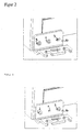
- FIG. 2 This fixed mounting position is in FIG. 2 , upper illustration reproduced. From this illustration it can be seen that the bearing block is fastened by means of two screws on the device, one of which is guided through the round hole 1 and another through the slot 2 shown on the left.
- the screw in the middle hole 1 is preferably removed when the screw is tightened in the long hole 2 shown on the left, and screwed into the further elongated hole 3 shown. Now, if the screw is easily solved in the hole 2, the bearing block 10 can be moved in the horizontal direction. After subsequent adjustment, the screws are tightened in the slots 2 and 3, as shown in FIG. 2 , lower illustration is reproduced.
- the present invention has the advantage that the two requirements for the arrangement of a bearing block, namely a well-defined fixation and further the possibility of adjustment, without the aid of tools or other additional parts can be done.
- the parts used are simple standard parts that cause no additional costs.
Landscapes
- Engineering & Computer Science (AREA)
- Mechanical Engineering (AREA)
- Refrigerator Housings (AREA)
- Hinges (AREA)
- Connection Of Plates (AREA)
Claims (5)
- Appareil de réfrigération et/ou de congélation avec au moins un support de palier pour le logement d'une ou de plusieurs portes, caractérisé en ce que le support de palier (10), dans le but du montage à un corps de l'appareil de réfrigération et/ou de congélation présente au moins un trou rond (1) et au moins un trou oblong (2), où le support de palier (10), dans le but du montage, est fixé dans une position de palier définie par au moins deux vis, en faisant passer une à travers le trou rond (1) et une autre à travers le trou oblong (2), caractérisé en ce que le support de palier (10), dans le but de l'ajustement dans la direction horizontale, présente un deuxième trou oblong (3) s'étendant parallèlement au premier trou oblong (2) dans lequel, avant ou après le déplacement du support de palier (10) dans la position souhaitée, une vis retirée peut être insérée, où au support de palier, le trou rond (1) ainsi que les trous oblongs (2, 3) se situent sur une ligne et sont disposés à la même hauteur au support de palier (10).
- Support de palier (10) selon la revendication 1, caractérisé en ce que le trou rond (1) est disposé entre les deux trous oblongs (2, 3).
- Support de palier (10) selon la revendication 1 ou 2, caractérisé en ce que le support de palier (10) présente une branche verticale à l'état monté, et en ce que le trou rond (1) ainsi que les deux trous oblongs (2, 3) sont disposés dans cette branche.
- Procédé d'agencement d'un support de palier (10) à un corps d'un appareil de réfrigération et/ou de congélation pour le logement d'une ou de plusieurs portes, où le support de palier (10), dans le but du montage, présente au moins un trou rond (1) et au moins un trou oblong (2), et où le support de palier (10), dans le but du montage, est fixé dans une position de support de palier définie par au moins deux vis, dont on fait passer une à travers le trou rond (1) et une autre à travers le trou oblong (2), caractérisé en ce que le support de palier (10) présente un deuxième trou oblong (3) s'étendant parallèlement au premier trou oblong (2), où au support de palier (10), le trou rond (1) ainsi que les trous oblongs (2, 3) se situent sur une ligne et sont disposés à la même hauteur au support de palier (10), et en ce que dans le but du déplacement du support de palier (10) dans la direction horizontale, la vis passée à travers le trou rond (1) est retirée et la vis se trouvant dans le premier trou oblong (2) est relâchée de sorte que le support de palier (10) est déplaçable, et en ce qu'avant ou après le déplacement du support de palier (10) dans la position souhaitée, une vis retirée est insérée dans le deuxième trou oblong (3) et, après le déplacement du support de palier (10) dans la position souhaitée, les deux vis se trouvant dans les trous oblongs (2, 3) sont serrées.
- Procédé selon la revendication 4, caractérisé en ce que le montage du support de palier (10) a lieu en ce que tout d'abord une vis est passée à travers le trou rond (1) et ensuite une autre vis à travers le premier trou oblong (2) du support de palier (10) et ensuite, les deux vis sont serrées.
Applications Claiming Priority (2)
| Application Number | Priority Date | Filing Date | Title |
|---|---|---|---|
| DE102006024188 | 2006-05-23 | ||
| DE102006039512A DE102006039512A1 (de) | 2006-05-23 | 2006-08-23 | Lagerbock |
Publications (3)
| Publication Number | Publication Date |
|---|---|
| EP1860264A2 EP1860264A2 (fr) | 2007-11-28 |
| EP1860264A3 EP1860264A3 (fr) | 2009-01-21 |
| EP1860264B1 true EP1860264B1 (fr) | 2012-04-25 |
Family
ID=38330035
Family Applications (1)
| Application Number | Title | Priority Date | Filing Date |
|---|---|---|---|
| EP20070010293 Not-in-force EP1860264B1 (fr) | 2006-05-23 | 2007-05-23 | Réfrigérateur et/ou congélateur |
Country Status (3)
| Country | Link |
|---|---|
| EP (1) | EP1860264B1 (fr) |
| DE (1) | DE102006039512A1 (fr) |
| ES (1) | ES2382353T3 (fr) |
Families Citing this family (2)
| Publication number | Priority date | Publication date | Assignee | Title |
|---|---|---|---|---|
| CN102322720A (zh) * | 2011-08-16 | 2012-01-18 | 合肥美的荣事达电冰箱有限公司 | 冰箱及其门体调节装置 |
| RU2632037C2 (ru) * | 2012-05-08 | 2017-10-02 | Бсх Хаусгерете Гмбх | Бытовой прибор, содержащий шарнир с опорным кронштейном |
Family Cites Families (5)
| Publication number | Priority date | Publication date | Assignee | Title |
|---|---|---|---|---|
| US3299573A (en) * | 1965-03-31 | 1967-01-24 | Stanley Works | Swinging door and hardware for mounting the same |
| US4999876A (en) | 1989-02-10 | 1991-03-19 | Richard Nass | Door jamb mountable hinge |
| US5355559A (en) * | 1993-04-26 | 1994-10-18 | Amerock Corporation | Hinge for inset doors |
| DE19825979A1 (de) * | 1998-06-10 | 1999-12-16 | Bsh Bosch Siemens Hausgeraete | Hausgerät, insbesondere Kühlgerät |
| DE10358731A1 (de) * | 2003-12-15 | 2005-07-14 | BSH Bosch und Siemens Hausgeräte GmbH | Gehäuse für ein Haushaltsgerät |
-
2006
- 2006-08-23 DE DE102006039512A patent/DE102006039512A1/de not_active Withdrawn
-
2007
- 2007-05-23 ES ES07010293T patent/ES2382353T3/es active Active
- 2007-05-23 EP EP20070010293 patent/EP1860264B1/fr not_active Not-in-force
Also Published As
| Publication number | Publication date |
|---|---|
| EP1860264A3 (fr) | 2009-01-21 |
| DE102006039512A1 (de) | 2007-11-29 |
| EP1860264A2 (fr) | 2007-11-28 |
| ES2382353T3 (es) | 2012-06-07 |
Similar Documents
| Publication | Publication Date | Title |
|---|---|---|
| EP2873792B1 (fr) | Penture | |
| EP2365783A2 (fr) | Support de serrage | |
| EP1764048A2 (fr) | Plaque ventrale | |
| DE202010013011U1 (de) | Befestigungsanordnung für die Montage von Beschlagteilen | |
| EP0984127A1 (fr) | Mécanisme de roulement pour porte coulissante | |
| DE102007034408B4 (de) | Halteeinrichtung für einen Querträger in einem elektrischen Schaltschrank, und Schaltschrank | |
| CH702627A2 (de) | Befestigungsvorrichtung und Einschubprofil. | |
| EP1877713B1 (fr) | Appareil de réfrigération et/ou de congélation | |
| EP2142044B1 (fr) | Dispositif et système pour influencer le mouvement d'un élément de meuble, dispositif de montage pour un tel dispositif et meuble | |
| EP3002400B1 (fr) | Penture de porte recouverte | |
| DE102012005092B3 (de) | Anordnung zum auswechselbaren Befestigen eines Biegewerkzeugs an einem einem Biegekopf einer Biegemaschine zugeordneten Halter | |
| EP1439269B1 (fr) | Etrier d'ancrage pour profilés pour installations sanitaires et chassis avec un tel étrier | |
| EP1860264A2 (fr) | Support de palier | |
| EP2760090A1 (fr) | Système de fixation et kit d'intégration pour le montage d'une passerelle de montage dans une armoire de commande | |
| DE102013110189A1 (de) | Einstellvorrichtung | |
| EP2267384B1 (fr) | Porte d'appareil avec connexion de porte | |
| EP1577032B1 (fr) | Guide-fil pour une machine à traiter des fils, en particulier une machine pour la fabrication de ressorts | |
| EP2778332A2 (fr) | Équerre de fixation pour une porte coulissante | |
| EP2754807A1 (fr) | Penture de porte dissimulée | |
| AT406328B (de) | Ausziehrahmen für hochschränke | |
| EP1243203B1 (fr) | Système de fixation pour glissières | |
| DE10209557A1 (de) | Bügel mit Einstellmechanismus zur Halterung von Türen | |
| DE102004054028A1 (de) | Vorrichtung zum Positionieren einer Tür | |
| DE202010000291U1 (de) | Bandlappenanordnung | |
| EP4245635B1 (fr) | Éclisse |
Legal Events
| Date | Code | Title | Description |
|---|---|---|---|
| PUAI | Public reference made under article 153(3) epc to a published international application that has entered the european phase |
Free format text: ORIGINAL CODE: 0009012 |
|
| AK | Designated contracting states |
Kind code of ref document: A2 Designated state(s): AT BE BG CH CY CZ DE DK EE ES FI FR GB GR HU IE IS IT LI LT LU LV MC MT NL PL PT RO SE SI SK TR |
|
| AX | Request for extension of the european patent |
Extension state: AL BA HR MK YU |
|
| PUAL | Search report despatched |
Free format text: ORIGINAL CODE: 0009013 |
|
| AK | Designated contracting states |
Kind code of ref document: A3 Designated state(s): AT BE BG CH CY CZ DE DK EE ES FI FR GB GR HU IE IS IT LI LT LU LV MC MT NL PL PT RO SE SI SK TR |
|
| AX | Request for extension of the european patent |
Extension state: AL BA HR MK RS |
|
| 17P | Request for examination filed |
Effective date: 20090518 |
|
| 17Q | First examination report despatched |
Effective date: 20090714 |
|
| AKX | Designation fees paid |
Designated state(s): DE ES FR IT |
|
| GRAP | Despatch of communication of intention to grant a patent |
Free format text: ORIGINAL CODE: EPIDOSNIGR1 |
|
| RTI1 | Title (correction) |
Free format text: REFRIGERATOR AND/OR FREEZER |
|
| GRAS | Grant fee paid |
Free format text: ORIGINAL CODE: EPIDOSNIGR3 |
|
| GRAA | (expected) grant |
Free format text: ORIGINAL CODE: 0009210 |
|
| AK | Designated contracting states |
Kind code of ref document: B1 Designated state(s): DE ES FR IT |
|
| RIN1 | Information on inventor provided before grant (corrected) |
Inventor name: SCHUBERT, RALF, DIPL.-ING. |
|
| REG | Reference to a national code |
Ref country code: ES Ref legal event code: FG2A Ref document number: 2382353 Country of ref document: ES Kind code of ref document: T3 Effective date: 20120607 |
|
| REG | Reference to a national code |
Ref country code: DE Ref legal event code: R096 Ref document number: 502007009751 Country of ref document: DE Effective date: 20120628 |
|
| PGFP | Annual fee paid to national office [announced via postgrant information from national office to epo] |
Ref country code: ES Payment date: 20120525 Year of fee payment: 6 |
|
| PLBE | No opposition filed within time limit |
Free format text: ORIGINAL CODE: 0009261 |
|
| STAA | Information on the status of an ep patent application or granted ep patent |
Free format text: STATUS: NO OPPOSITION FILED WITHIN TIME LIMIT |
|
| 26N | No opposition filed |
Effective date: 20130128 |
|
| REG | Reference to a national code |
Ref country code: DE Ref legal event code: R097 Ref document number: 502007009751 Country of ref document: DE Effective date: 20130128 |
|
| PGFP | Annual fee paid to national office [announced via postgrant information from national office to epo] |
Ref country code: IT Payment date: 20130524 Year of fee payment: 7 Ref country code: FR Payment date: 20130605 Year of fee payment: 7 |
|
| REG | Reference to a national code |
Ref country code: FR Ref legal event code: ST Effective date: 20150130 |
|
| PG25 | Lapsed in a contracting state [announced via postgrant information from national office to epo] |
Ref country code: IT Free format text: LAPSE BECAUSE OF NON-PAYMENT OF DUE FEES Effective date: 20140523 |
|
| PG25 | Lapsed in a contracting state [announced via postgrant information from national office to epo] |
Ref country code: FR Free format text: LAPSE BECAUSE OF NON-PAYMENT OF DUE FEES Effective date: 20140602 |
|
| REG | Reference to a national code |
Ref country code: ES Ref legal event code: FD2A Effective date: 20160129 |
|
| PG25 | Lapsed in a contracting state [announced via postgrant information from national office to epo] |
Ref country code: ES Free format text: LAPSE BECAUSE OF NON-PAYMENT OF DUE FEES Effective date: 20140524 |
|
| PGFP | Annual fee paid to national office [announced via postgrant information from national office to epo] |
Ref country code: DE Payment date: 20180521 Year of fee payment: 12 |
|
| REG | Reference to a national code |
Ref country code: DE Ref legal event code: R119 Ref document number: 502007009751 Country of ref document: DE |
|
| PG25 | Lapsed in a contracting state [announced via postgrant information from national office to epo] |
Ref country code: DE Free format text: LAPSE BECAUSE OF NON-PAYMENT OF DUE FEES Effective date: 20191203 |