EP1860293A2 - Reduzieren von Stickoxiden unter Verwendung von aus Motorkraftstoff und Abgas erzeugtem Wasserstoff - Google Patents
Reduzieren von Stickoxiden unter Verwendung von aus Motorkraftstoff und Abgas erzeugtem Wasserstoff Download PDFInfo
- Publication number
- EP1860293A2 EP1860293A2 EP07116633A EP07116633A EP1860293A2 EP 1860293 A2 EP1860293 A2 EP 1860293A2 EP 07116633 A EP07116633 A EP 07116633A EP 07116633 A EP07116633 A EP 07116633A EP 1860293 A2 EP1860293 A2 EP 1860293A2
- Authority
- EP
- European Patent Office
- Prior art keywords
- nox
- exhaust
- engine
- fuel
- reducing
- Prior art date
- Legal status (The legal status is an assumption and is not a legal conclusion. Google has not performed a legal analysis and makes no representation as to the accuracy of the status listed.)
- Withdrawn
Links
Images



Classifications
-
- F—MECHANICAL ENGINEERING; LIGHTING; HEATING; WEAPONS; BLASTING
- F02—COMBUSTION ENGINES; HOT-GAS OR COMBUSTION-PRODUCT ENGINE PLANTS
- F02B—INTERNAL-COMBUSTION PISTON ENGINES; COMBUSTION ENGINES IN GENERAL
- F02B37/00—Engines characterised by provision of pumps driven at least for part of the time by exhaust
-
- B—PERFORMING OPERATIONS; TRANSPORTING
- B01—PHYSICAL OR CHEMICAL PROCESSES OR APPARATUS IN GENERAL
- B01D—SEPARATION
- B01D53/00—Separation of gases or vapours; Recovering vapours of volatile solvents from gases; Chemical or biological purification of waste gases, e.g. engine exhaust gases, smoke, fumes, flue gases, aerosols
- B01D53/34—Chemical or biological purification of waste gases
- B01D53/92—Chemical or biological purification of waste gases of engine exhaust gases
- B01D53/94—Chemical or biological purification of waste gases of engine exhaust gases by catalytic processes
- B01D53/9404—Removing only nitrogen compounds
- B01D53/9409—Nitrogen oxides
- B01D53/9431—Processes characterised by a specific device
-
- F—MECHANICAL ENGINEERING; LIGHTING; HEATING; WEAPONS; BLASTING
- F01—MACHINES OR ENGINES IN GENERAL; ENGINE PLANTS IN GENERAL; STEAM ENGINES
- F01N—GAS-FLOW SILENCERS OR EXHAUST APPARATUS FOR MACHINES OR ENGINES IN GENERAL; GAS-FLOW SILENCERS OR EXHAUST APPARATUS FOR INTERNAL-COMBUSTION ENGINES
- F01N13/00—Exhaust or silencing apparatus characterised by constructional features
- F01N13/011—Exhaust or silencing apparatus characterised by constructional features having two or more purifying devices arranged in parallel
-
- F—MECHANICAL ENGINEERING; LIGHTING; HEATING; WEAPONS; BLASTING
- F01—MACHINES OR ENGINES IN GENERAL; ENGINE PLANTS IN GENERAL; STEAM ENGINES
- F01N—GAS-FLOW SILENCERS OR EXHAUST APPARATUS FOR MACHINES OR ENGINES IN GENERAL; GAS-FLOW SILENCERS OR EXHAUST APPARATUS FOR INTERNAL-COMBUSTION ENGINES
- F01N3/00—Exhaust or silencing apparatus having means for purifying, rendering innocuous, or otherwise treating exhaust
- F01N3/08—Exhaust or silencing apparatus having means for purifying, rendering innocuous, or otherwise treating exhaust for rendering innocuous
- F01N3/0807—Exhaust or silencing apparatus having means for purifying, rendering innocuous, or otherwise treating exhaust for rendering innocuous by using absorbents or adsorbents
-
- F—MECHANICAL ENGINEERING; LIGHTING; HEATING; WEAPONS; BLASTING
- F01—MACHINES OR ENGINES IN GENERAL; ENGINE PLANTS IN GENERAL; STEAM ENGINES
- F01N—GAS-FLOW SILENCERS OR EXHAUST APPARATUS FOR MACHINES OR ENGINES IN GENERAL; GAS-FLOW SILENCERS OR EXHAUST APPARATUS FOR INTERNAL-COMBUSTION ENGINES
- F01N3/00—Exhaust or silencing apparatus having means for purifying, rendering innocuous, or otherwise treating exhaust
- F01N3/08—Exhaust or silencing apparatus having means for purifying, rendering innocuous, or otherwise treating exhaust for rendering innocuous
- F01N3/0807—Exhaust or silencing apparatus having means for purifying, rendering innocuous, or otherwise treating exhaust for rendering innocuous by using absorbents or adsorbents
- F01N3/0814—Exhaust or silencing apparatus having means for purifying, rendering innocuous, or otherwise treating exhaust for rendering innocuous by using absorbents or adsorbents combined with catalytic converters, e.g. NOx absorption/storage reduction catalysts
-
- F—MECHANICAL ENGINEERING; LIGHTING; HEATING; WEAPONS; BLASTING
- F01—MACHINES OR ENGINES IN GENERAL; ENGINE PLANTS IN GENERAL; STEAM ENGINES
- F01N—GAS-FLOW SILENCERS OR EXHAUST APPARATUS FOR MACHINES OR ENGINES IN GENERAL; GAS-FLOW SILENCERS OR EXHAUST APPARATUS FOR INTERNAL-COMBUSTION ENGINES
- F01N3/00—Exhaust or silencing apparatus having means for purifying, rendering innocuous, or otherwise treating exhaust
- F01N3/08—Exhaust or silencing apparatus having means for purifying, rendering innocuous, or otherwise treating exhaust for rendering innocuous
- F01N3/0807—Exhaust or silencing apparatus having means for purifying, rendering innocuous, or otherwise treating exhaust for rendering innocuous by using absorbents or adsorbents
- F01N3/0828—Exhaust or silencing apparatus having means for purifying, rendering innocuous, or otherwise treating exhaust for rendering innocuous by using absorbents or adsorbents characterised by the absorbed or adsorbed substances
- F01N3/0842—Nitrogen oxides
-
- F—MECHANICAL ENGINEERING; LIGHTING; HEATING; WEAPONS; BLASTING
- F01—MACHINES OR ENGINES IN GENERAL; ENGINE PLANTS IN GENERAL; STEAM ENGINES
- F01N—GAS-FLOW SILENCERS OR EXHAUST APPARATUS FOR MACHINES OR ENGINES IN GENERAL; GAS-FLOW SILENCERS OR EXHAUST APPARATUS FOR INTERNAL-COMBUSTION ENGINES
- F01N3/00—Exhaust or silencing apparatus having means for purifying, rendering innocuous, or otherwise treating exhaust
- F01N3/08—Exhaust or silencing apparatus having means for purifying, rendering innocuous, or otherwise treating exhaust for rendering innocuous
- F01N3/0807—Exhaust or silencing apparatus having means for purifying, rendering innocuous, or otherwise treating exhaust for rendering innocuous by using absorbents or adsorbents
- F01N3/0871—Exhaust or silencing apparatus having means for purifying, rendering innocuous, or otherwise treating exhaust for rendering innocuous by using absorbents or adsorbents using means for controlling, e.g. purging, the absorbents or adsorbents
- F01N3/0878—Bypassing absorbents or adsorbents
-
- F—MECHANICAL ENGINEERING; LIGHTING; HEATING; WEAPONS; BLASTING
- F01—MACHINES OR ENGINES IN GENERAL; ENGINE PLANTS IN GENERAL; STEAM ENGINES
- F01N—GAS-FLOW SILENCERS OR EXHAUST APPARATUS FOR MACHINES OR ENGINES IN GENERAL; GAS-FLOW SILENCERS OR EXHAUST APPARATUS FOR INTERNAL-COMBUSTION ENGINES
- F01N3/00—Exhaust or silencing apparatus having means for purifying, rendering innocuous, or otherwise treating exhaust
- F01N3/08—Exhaust or silencing apparatus having means for purifying, rendering innocuous, or otherwise treating exhaust for rendering innocuous
- F01N3/10—Exhaust or silencing apparatus having means for purifying, rendering innocuous, or otherwise treating exhaust for rendering innocuous by thermal or catalytic conversion of noxious components of exhaust
- F01N3/18—Exhaust or silencing apparatus having means for purifying, rendering innocuous, or otherwise treating exhaust for rendering innocuous by thermal or catalytic conversion of noxious components of exhaust characterised by methods of operation; Control
- F01N3/20—Exhaust or silencing apparatus having means for purifying, rendering innocuous, or otherwise treating exhaust for rendering innocuous by thermal or catalytic conversion of noxious components of exhaust characterised by methods of operation; Control specially adapted for catalytic conversion
- F01N3/206—Adding periodically or continuously substances to exhaust gases for promoting purification, e.g. catalytic material in liquid form, NOx reducing agents
- F01N3/2066—Selective catalytic reduction [SCR]
-
- F—MECHANICAL ENGINEERING; LIGHTING; HEATING; WEAPONS; BLASTING
- F01—MACHINES OR ENGINES IN GENERAL; ENGINE PLANTS IN GENERAL; STEAM ENGINES
- F01N—GAS-FLOW SILENCERS OR EXHAUST APPARATUS FOR MACHINES OR ENGINES IN GENERAL; GAS-FLOW SILENCERS OR EXHAUST APPARATUS FOR INTERNAL-COMBUSTION ENGINES
- F01N2240/00—Combination or association of two or more different exhaust treating devices, or of at least one such device with an auxiliary device, not covered by indexing codes F01N2230/00 or F01N2250/00, one of the devices being
- F01N2240/02—Combination or association of two or more different exhaust treating devices, or of at least one such device with an auxiliary device, not covered by indexing codes F01N2230/00 or F01N2250/00, one of the devices being a heat exchanger
-
- F—MECHANICAL ENGINEERING; LIGHTING; HEATING; WEAPONS; BLASTING
- F01—MACHINES OR ENGINES IN GENERAL; ENGINE PLANTS IN GENERAL; STEAM ENGINES
- F01N—GAS-FLOW SILENCERS OR EXHAUST APPARATUS FOR MACHINES OR ENGINES IN GENERAL; GAS-FLOW SILENCERS OR EXHAUST APPARATUS FOR INTERNAL-COMBUSTION ENGINES
- F01N2240/00—Combination or association of two or more different exhaust treating devices, or of at least one such device with an auxiliary device, not covered by indexing codes F01N2230/00 or F01N2250/00, one of the devices being
- F01N2240/22—Combination or association of two or more different exhaust treating devices, or of at least one such device with an auxiliary device, not covered by indexing codes F01N2230/00 or F01N2250/00, one of the devices being a condensation chamber
-
- F—MECHANICAL ENGINEERING; LIGHTING; HEATING; WEAPONS; BLASTING
- F01—MACHINES OR ENGINES IN GENERAL; ENGINE PLANTS IN GENERAL; STEAM ENGINES
- F01N—GAS-FLOW SILENCERS OR EXHAUST APPARATUS FOR MACHINES OR ENGINES IN GENERAL; GAS-FLOW SILENCERS OR EXHAUST APPARATUS FOR INTERNAL-COMBUSTION ENGINES
- F01N2240/00—Combination or association of two or more different exhaust treating devices, or of at least one such device with an auxiliary device, not covered by indexing codes F01N2230/00 or F01N2250/00, one of the devices being
- F01N2240/30—Combination or association of two or more different exhaust treating devices, or of at least one such device with an auxiliary device, not covered by indexing codes F01N2230/00 or F01N2250/00, one of the devices being a fuel reformer
-
- F—MECHANICAL ENGINEERING; LIGHTING; HEATING; WEAPONS; BLASTING
- F01—MACHINES OR ENGINES IN GENERAL; ENGINE PLANTS IN GENERAL; STEAM ENGINES
- F01N—GAS-FLOW SILENCERS OR EXHAUST APPARATUS FOR MACHINES OR ENGINES IN GENERAL; GAS-FLOW SILENCERS OR EXHAUST APPARATUS FOR INTERNAL-COMBUSTION ENGINES
- F01N2410/00—By-passing, at least partially, exhaust from inlet to outlet of apparatus, to atmosphere or to other device
- F01N2410/12—By-passing, at least partially, exhaust from inlet to outlet of apparatus, to atmosphere or to other device in case of absorption, adsorption or desorption of exhaust gas constituents
-
- F—MECHANICAL ENGINEERING; LIGHTING; HEATING; WEAPONS; BLASTING
- F01—MACHINES OR ENGINES IN GENERAL; ENGINE PLANTS IN GENERAL; STEAM ENGINES
- F01N—GAS-FLOW SILENCERS OR EXHAUST APPARATUS FOR MACHINES OR ENGINES IN GENERAL; GAS-FLOW SILENCERS OR EXHAUST APPARATUS FOR INTERNAL-COMBUSTION ENGINES
- F01N2570/00—Exhaust treating apparatus eliminating, absorbing or adsorbing specific elements or compounds
- F01N2570/22—Water or humidity
-
- F—MECHANICAL ENGINEERING; LIGHTING; HEATING; WEAPONS; BLASTING
- F01—MACHINES OR ENGINES IN GENERAL; ENGINE PLANTS IN GENERAL; STEAM ENGINES
- F01N—GAS-FLOW SILENCERS OR EXHAUST APPARATUS FOR MACHINES OR ENGINES IN GENERAL; GAS-FLOW SILENCERS OR EXHAUST APPARATUS FOR INTERNAL-COMBUSTION ENGINES
- F01N2610/00—Adding substances to exhaust gases
- F01N2610/03—Adding substances to exhaust gases the substance being hydrocarbons, e.g. engine fuel
-
- F—MECHANICAL ENGINEERING; LIGHTING; HEATING; WEAPONS; BLASTING
- F01—MACHINES OR ENGINES IN GENERAL; ENGINE PLANTS IN GENERAL; STEAM ENGINES
- F01N—GAS-FLOW SILENCERS OR EXHAUST APPARATUS FOR MACHINES OR ENGINES IN GENERAL; GAS-FLOW SILENCERS OR EXHAUST APPARATUS FOR INTERNAL-COMBUSTION ENGINES
- F01N2610/00—Adding substances to exhaust gases
- F01N2610/04—Adding substances to exhaust gases the substance being hydrogen
-
- F—MECHANICAL ENGINEERING; LIGHTING; HEATING; WEAPONS; BLASTING
- F01—MACHINES OR ENGINES IN GENERAL; ENGINE PLANTS IN GENERAL; STEAM ENGINES
- F01N—GAS-FLOW SILENCERS OR EXHAUST APPARATUS FOR MACHINES OR ENGINES IN GENERAL; GAS-FLOW SILENCERS OR EXHAUST APPARATUS FOR INTERNAL-COMBUSTION ENGINES
- F01N2610/00—Adding substances to exhaust gases
- F01N2610/10—Adding substances to exhaust gases the substance being heated, e.g. by heating tank or supply line of the added substance
-
- F—MECHANICAL ENGINEERING; LIGHTING; HEATING; WEAPONS; BLASTING
- F01—MACHINES OR ENGINES IN GENERAL; ENGINE PLANTS IN GENERAL; STEAM ENGINES
- F01N—GAS-FLOW SILENCERS OR EXHAUST APPARATUS FOR MACHINES OR ENGINES IN GENERAL; GAS-FLOW SILENCERS OR EXHAUST APPARATUS FOR INTERNAL-COMBUSTION ENGINES
- F01N5/00—Exhaust or silencing apparatus combined or associated with devices profiting by exhaust energy
- F01N5/02—Exhaust or silencing apparatus combined or associated with devices profiting by exhaust energy the devices using heat
-
- Y—GENERAL TAGGING OF NEW TECHNOLOGICAL DEVELOPMENTS; GENERAL TAGGING OF CROSS-SECTIONAL TECHNOLOGIES SPANNING OVER SEVERAL SECTIONS OF THE IPC; TECHNICAL SUBJECTS COVERED BY FORMER USPC CROSS-REFERENCE ART COLLECTIONS [XRACs] AND DIGESTS
- Y02—TECHNOLOGIES OR APPLICATIONS FOR MITIGATION OR ADAPTATION AGAINST CLIMATE CHANGE
- Y02T—CLIMATE CHANGE MITIGATION TECHNOLOGIES RELATED TO TRANSPORTATION
- Y02T10/00—Road transport of goods or passengers
- Y02T10/10—Internal combustion engine [ICE] based vehicles
- Y02T10/12—Improving ICE efficiencies
Definitions
- This invention relates to reducing oxides of nitrogen (NOx) in the exhaust of hydrocarbon-fuelled, internal combustion engines and more particularly to using hydrogen generators, such as catalytic partial oxidizers (CPOx), non-catalytic (homogeneous) partial oxidizers (POx), or auto thermal reformers (ATR), to generate from engine fuel and exhaust, streams including hydrogen and carbon monoxide for use in NOx catalytic converters or NOx-reducing adsorption filters.
- hydrogen generators such as catalytic partial oxidizers (CPOx), non-catalytic (homogeneous) partial oxidizers (POx), or auto thermal reformers (ATR)
- the Environmental Protection Agency has set, for 2007 and beyond, vehicle internal combustion engine emission requirements; one exemplary requirement for diesel engines, is NOx and non-methane hydrocarbons below 0.20 grams bhp-hr and 0.14 grams/bhp-hr, respectively. This contrasts with current standards of 4.0 grams/bhp-hr and 1.3 grams/bhp-hr, respectively.
- the catalytic converters must accomplish a significant reduction in NOx.
- Apparatus that oxidizes engine fuel to provide a mix that enhances NOx reduction is disclosed in U.S. patent 5,412,946 , in POT published application WO 01/34950 , and U.S. patent application Publication 2001/41153 .
- Purposes of the present invention include: improvement in the reduction of NOx to nitrogen and other harmless gases; achieving NOx reduction that meets EPA 2007 NOx emission requirements; and providing improved generation of hydrogen in and for an internal combustion engine exhaust emission reduction system.
- the present invention provides a system for reducing oxides of nitrogen (NOx) in the exhaust of a hydrocarbon-fuelled, internal combustion engine (9) which operates with fuel from a source (12) and which provides engine exhaust in an exhaust pipe (21) and receives air from an air inlet (11), comprising:
- the invention provides a method of reducing oxides of nitrogen (NOx) in the exhaust of a system including a hydrocarbon-fuelled engine (9) that provides engine exhaust (21) containing NOx, said method comprising:
- moisture and possibly oxygen, derived from the exhaust of a hydrocarbon-fuelled, internal combustion engine are processed along with fuel from the engine's fuel tank in a fuel processor, which may be a catalytic partial oxidation reformer, a non catalytic (homogeneous) partial oxidation reformer, or an auto thermal reformer, to generate a stream of hydrogen and carbon monoxide which is used, either directly or following the reaction of NOx with other compounds, to eliminate NOx in the exhaust.
- a fuel processor which may be a catalytic partial oxidation reformer, a non catalytic (homogeneous) partial oxidation reformer, or an auto thermal reformer, to generate a stream of hydrogen and carbon monoxide which is used, either directly or following the reaction of NOx with other compounds, to eliminate NOx in the exhaust.
- the hydrogen-rich stream may either (a) be mixed with the main exhaust stream for processing in a NOx-reducing catalytic converter, or (b) used to regenerate NOx traps following the formation of nitrogen-containing compounds by reaction of the exhaust with adsorbent in the NOx traps.
- air is also fed, such as from ambient, to the fuel processor; steam is extracted from engine exhaust and from NOx trap effluent; air is humidified; and fuel is vaporized.
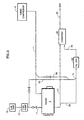
- an engine 9 has a conventional turbo compressor 10 feeding an air inlet line 11, a hydrocarbon fuel tank 12, and a fuel pump 13.
- the fuel may be diesel fuel, gasoline, natural gas, liquid petroleum gas, or propane.
- the fuel is fed by a first line 17 to the engine for combustion with the air, and is fed by a second line 18 to a mixer 19 in a pipe 20 that feeds a small amount of exhaust from an exhaust pipe 21 to a hydrogen generator 22.
- the hydrogen generator 22 may be a catalytic partial oxidizer (CPOx), a non-catalytic (homogeneous) partial oxidizer, or an auto thermal reformer (ATR).
- the hydrogen generator if it is a CPOx, foam monolith or other form of catalyst, which may comprise a group VIII metal, preferably nickel, cobalt, rhodium, iridium or platinum, convert fuel along with hydrocarbons, water and oxygen into a mix of hydrogen, CO and CO2.
- a group VIII metal preferably nickel, cobalt, rhodium, iridium or platinum
- This is provided through a conduit 26 to a NOx reducing catalytic converter 28, the output of which is exhausted by a pipe 29, typically to ambient.
- the converter 28 is of the type commonly used in diesel engines.
- the water content will vary between 2% and 9% and the oxygen content will vary between 5% and 17%.
- diesel fuel it may require up to 7% of consumed fuel to clean up the exhaust, which is acceptable.
- the exhaust-hydrogen, oxides of nitrogen, carbon monoxide and carbon dioxide- is converted to mainly nitrogen, water, and carbon dioxide, with traces of non-methane hydrocarbons and oxides of nitrogen.
- the invention will permit reducing the NOx to 0.20 grams/bhp/hr and non-methane hydrocarbons to 0.14 grams/bhp/hr.
- air may be fed by a conduit 30 from the air inlet line 11 for mixture with the fuel in pipe 18.
- Figs. 1 and 2 are rudimentary embodiments of the present invention.
- the NOx is treated continuously in a known converter.
- a more effective elimination of NOx comprises utilizing adsorption traps in alternating collection/regeneration cycles.
- a pair of NOx adsorbent traps 35, 36 are alternatively connected by corresponding valves 40-43 to either the conduit 26 with hydrogencontaining gas from the generator 22, or to a pipe 48 containing engine exhaust.
- the valves are controlled so that engine exhaust is allowed to flow in one of the traps 35, 36 for a period of time which is less than the time necessary to saturate it with NOx, and then the valves are switched so that exhaust flows in the other NOx trap, while the first NOx trap is regenerated by the hydrogen and carbon monoxide from the generator 22.
- the NOx traps may, for example, contain barium carbonate (BaCO 3 ) as the adsorbent: when the diesel exhaust is adsorbed by the barium carbonate, a reaction generates barium nitrate. 2NOx + BaCO 3 -> Ba(NO 3 )2+ CO 2
- the barium nitrate is converted back to barium carbonate, as follows: 3H 2 + 2CO + Ba(NO 3 ) 2 -> BaCO 3 + N 2 +3H 2 O + CO 2
- Fig. 3 also illustrates that preferred embodiments of the invention may use a heat exchanger 50 to cause heat of the engine exhaust to vaporize the fuel in the line 18 before applying it to the reformer, which is particularly useful in the case of a CPOx oxidizer.
- a CPOx oxidizer is preferred because it is very small and can run with low steam carbon ratios and high turndown ratios without soot or carbon formation.
- diesel engine exhaust contains particulates (soot) and oxides of sulphur (SOx), which may deactivate the CPOx catalyst in a relatively short period of time. Therefore, a non-catalytic (homogeneous) partial oxidizer may be selected as the hydrogen generator 22.
- the percentage of hydrogen produced is only slightly less than that produced by a CPOx. It is easily started by employing a simple spark plug, as is known.
- POx is cheaper than CPOx; control of the O 2 /C ratio is known (similar to engine O 2 /fuel ratio), and simpler; SOx and soot do not affect it; and there is no steam/C ratio problem.
- a water recovery unit (WRU) 52 receives air from the air inlet 11 and a portion of the engine exhaust in a line 53.
- the WRU contains special materials that have a high degree of moisture diffusivity, one example of which is that sold under the trade name NAFION TM .
- the WRU extracts moisture (steam) from the exhaust stream and imparts it into the air stream, thereby to provide both oxygen and steam to the generator 22 in greater concentration in the air stream than it appears in the exhaust stream itself.
- the maximum temperature at which some material in the WRU will function is less than 250°C and the lower the temperature, the better the performance, whereas the temperature of diesel engine exhaust is in the range of 110°C-290°C.
- the engine exhaust is fed from the pipe 20 through two heat exchangers 55, 56 to vaporize the fuel (as described hereinbefore) and to further heat the exhaust stream of the WRU 52 on a line 58, before applying it to the generator 22. Since the steam level in the exhaust is relatively low, on the order of between 2 and 6 mol%, recovering sufficient steam to feed the generator 22 requires cooling a sufficient portion of exhaust, which the heat exchangers 55, 56 serve to do. However, further cooling can be achieved as illustrated in Fig. 5 by providing an additional heat exchanger 60, which receives all of the air in the air inlet line 11 to significantly cool the exhaust in the line 53 before it is applied to the water recovery unit 52.
- the effluent of the NOx traps 35, 36 may be as high as 50% water (steam), since all of the hydrogen produced by the generator 22 is converted to water during the reducing reaction (the regeneration formula hereinbefore).
- a WRU 63 receives air from the air inlet 11 and the effluent of whichever NOx trap 35, 36 is being regenerated at any moment in time.
- a pair of valves 64, 65 work in conjunction with the valves 40-43 such that when the valves 40, 42 are open the valve 64 will be open, and when the valves 41, 42 are open, the valve 65 will be open.
- the WRU 63 extracts water from the effluent, which is picked up by the air.
- the humidified air is passed through a heat exchanger 68 for application to the generator 22 with the vaporized fuel from the heat exchanger 50.
- heat from the exhaust of the engine is used to vaporize fuel in the heat exchanger 50 and to heat up humidified air from the air inlet 11 in the heat exchanger 68 as well as another, very small heat exchanger 71.
- the warm air from the heat exchanger 71 is brought to an air-bubbling humidifier 72, which is supplied water from a condenser 76 to humidify the warm air.
- the humidified air is warmed further in the heat exchanger 68 before being mixed with the vaporized fuel from the heat exchanger 50 for application to the reformer.
- the condenser 76 utilizes the full volume of air in the air inlet 11 to cool off the effluent from the NOx traps 35, 36 thereby condensing the water there from. This water is then drained and fed over to the humidifier 72, where it is taken up by the warm air from the heat exchanger 71.
Landscapes
- Engineering & Computer Science (AREA)
- Chemical & Material Sciences (AREA)
- Combustion & Propulsion (AREA)
- Mechanical Engineering (AREA)
- General Engineering & Computer Science (AREA)
- Chemical Kinetics & Catalysis (AREA)
- Health & Medical Sciences (AREA)
- Biomedical Technology (AREA)
- Toxicology (AREA)
- Environmental & Geological Engineering (AREA)
- Analytical Chemistry (AREA)
- General Chemical & Material Sciences (AREA)
- Oil, Petroleum & Natural Gas (AREA)
- Exhaust Gas After Treatment (AREA)
- Treating Waste Gases (AREA)
- Catalysts (AREA)
- Solid Fuels And Fuel-Associated Substances (AREA)
- Hydrogen, Water And Hydrids (AREA)
Applications Claiming Priority (2)
| Application Number | Priority Date | Filing Date | Title |
|---|---|---|---|
| US10/159,369 US6895746B2 (en) | 2002-05-31 | 2002-05-31 | Reducing oxides of nitrogen using hydrogen generated from engine fuel and exhaust |
| EP03728901A EP1552119B1 (de) | 2002-05-31 | 2003-05-13 | Reduzieren von stickoxiden unter verwendung von aus motorkraftstoff und abgas erzeugtem wasserstoff |
Related Parent Applications (1)
| Application Number | Title | Priority Date | Filing Date |
|---|---|---|---|
| EP03728901A Division EP1552119B1 (de) | 2002-05-31 | 2003-05-13 | Reduzieren von stickoxiden unter verwendung von aus motorkraftstoff und abgas erzeugtem wasserstoff |
Publications (2)
| Publication Number | Publication Date |
|---|---|
| EP1860293A2 true EP1860293A2 (de) | 2007-11-28 |
| EP1860293A3 EP1860293A3 (de) | 2007-12-05 |
Family
ID=29582882
Family Applications (2)
| Application Number | Title | Priority Date | Filing Date |
|---|---|---|---|
| EP03728901A Expired - Lifetime EP1552119B1 (de) | 2002-05-31 | 2003-05-13 | Reduzieren von stickoxiden unter verwendung von aus motorkraftstoff und abgas erzeugtem wasserstoff |
| EP07116633A Withdrawn EP1860293A3 (de) | 2002-05-31 | 2003-05-13 | Reduzieren von Stickoxiden unter Verwendung von aus Motorkraftstoff und Abgas erzeugtem Wasserstoff |
Family Applications Before (1)
| Application Number | Title | Priority Date | Filing Date |
|---|---|---|---|
| EP03728901A Expired - Lifetime EP1552119B1 (de) | 2002-05-31 | 2003-05-13 | Reduzieren von stickoxiden unter verwendung von aus motorkraftstoff und abgas erzeugtem wasserstoff |
Country Status (7)
| Country | Link |
|---|---|
| US (1) | US6895746B2 (de) |
| EP (2) | EP1552119B1 (de) |
| JP (1) | JP2006511747A (de) |
| AT (1) | ATE377698T1 (de) |
| AU (1) | AU2003234560A1 (de) |
| DE (1) | DE60317360T2 (de) |
| WO (1) | WO2003102390A1 (de) |
Cited By (1)
| Publication number | Priority date | Publication date | Assignee | Title |
|---|---|---|---|---|
| DE102009016097A1 (de) * | 2009-04-03 | 2010-10-07 | Fev Motorentechnik Gmbh | Abgasanlage eines Fahrzeugs mit einer Brennkraftmaschine und Verfahren zur Kühlung eines Abgasstroms in einem Abgasstrang eines Fahrzeugs |
Families Citing this family (37)
| Publication number | Priority date | Publication date | Assignee | Title |
|---|---|---|---|---|
| US7765794B2 (en) * | 2001-05-04 | 2010-08-03 | Nco2 Company Llc | Method and system for obtaining exhaust gas for use in augmenting crude oil production |
| US7021048B2 (en) * | 2002-01-25 | 2006-04-04 | Arvin Technologies, Inc. | Combination emission abatement assembly and method of operating the same |
| US6810658B2 (en) * | 2002-03-08 | 2004-11-02 | Daimlerchrysler Ag | Exhaust-gas purification installation and exhaust-gas purification method for purifying an exhaust gas from an internal combustion engine |
| US6758035B2 (en) * | 2002-09-18 | 2004-07-06 | Arvin Technologies, Inc. | Method and apparatus for purging SOX from a NOX trap |
| DE10251472A1 (de) * | 2002-11-06 | 2004-05-19 | Robert Bosch Gmbh | Verfahren zur Nachbehandlung von Abgasen und Anordnung hierzu |
| US6832473B2 (en) * | 2002-11-21 | 2004-12-21 | Delphi Technologies, Inc. | Method and system for regenerating NOx adsorbers and/or particulate filters |
| US7409823B2 (en) * | 2003-06-30 | 2008-08-12 | Delphi Technologies, Inc. | Method and apparatus for delivery of supplemental material to an exhaust gas feedstream with supplemental air assistance |
| US7601316B2 (en) * | 2003-09-08 | 2009-10-13 | Shell Oil Company | Method of reducing NOx and particulates from internal combustion engines |
| US20050193724A1 (en) * | 2004-02-27 | 2005-09-08 | Southwest Research Institute | Oxygen-enriched feedgas for reformer in emissions control system |
| JP4753407B2 (ja) * | 2004-03-25 | 2011-08-24 | 東京瓦斯株式会社 | 発電及び動力装置 |
| US20050242588A1 (en) * | 2004-04-30 | 2005-11-03 | Washington Krik B | Integrated fuel cell and additive gas supply system for a power generation system including a combustion engine |
| US20050274107A1 (en) * | 2004-06-14 | 2005-12-15 | Ke Liu | Reforming unvaporized, atomized hydrocarbon fuel |
| US6955042B1 (en) * | 2004-06-30 | 2005-10-18 | Hydrogensource Llc | CPO regenerated lean NOx trap with no moving parts |
| DE102004032287B4 (de) * | 2004-07-02 | 2007-01-11 | J. Eberspächer GmbH & Co. KG | Abgasanlage |
| WO2006010277A2 (en) * | 2004-07-29 | 2006-02-02 | Nxtgen Emission Controls Inc. | Integrated system for reducing fuel consumption and emissions in an internal combustion engine |
| US20060042565A1 (en) * | 2004-08-26 | 2006-03-02 | Eaton Corporation | Integrated fuel injection system for on-board fuel reformer |
| US20060042236A1 (en) * | 2004-09-01 | 2006-03-02 | Kabasin Daniel F | Method and apparatus for controlling exhaust gas flow rate |
| US8136345B2 (en) * | 2004-09-21 | 2012-03-20 | Shell Oil Company | Internal combustion engine exhaust treatment having a single valve directing exhaust to dual NOx traps |
| US8006484B2 (en) * | 2005-02-14 | 2011-08-30 | Eaton Corporation | Systems and methods for reducing emissions of internal combustion engines using a fuel processor bypass |
| US7743602B2 (en) * | 2005-06-21 | 2010-06-29 | Exxonmobil Research And Engineering Co. | Reformer assisted lean NOx catalyst aftertreatment system and method |
| US7803338B2 (en) * | 2005-06-21 | 2010-09-28 | Exonmobil Research And Engineering Company | Method and apparatus for combination catalyst for reduction of NOx in combustion products |
| US20070033929A1 (en) * | 2005-08-11 | 2007-02-15 | Arvinmeritor Emissions Technologies Gmbh | Apparatus with in situ fuel reformer and associated method |
| US7216481B2 (en) * | 2005-09-23 | 2007-05-15 | Delphi Technologies, Inc. | Method and apparatus for regeneration of engine exhaust aftertreatment devices |
| US7712308B2 (en) * | 2005-11-08 | 2010-05-11 | Tenneco Automotive Operating Company Inc. | Selective catalyst reduction of nitrogen oxides with hydrogen |
| DE102005056359A1 (de) * | 2005-11-25 | 2007-05-31 | Arvinmeritor Emissions Technologies Gmbh | Baugruppe und Verfahren zur Erzeugung eines wasserstoffhaltigen Gases zur Regeneration eines Kfz-Abgasreinigungssystems |
| US7767181B2 (en) * | 2006-06-30 | 2010-08-03 | Caterpillar Inc | System and method for ammonia production |
| FR2913056A1 (fr) * | 2007-02-23 | 2008-08-29 | Renault Sas | Procede de purge d'un piege a oxydes d'azote par injection de reformat et dispositif associe |
| US8061120B2 (en) * | 2007-07-30 | 2011-11-22 | Herng Shinn Hwang | Catalytic EGR oxidizer for IC engines and gas turbines |
| US20090173061A1 (en) * | 2008-01-09 | 2009-07-09 | General Electric Company | OPTIMIZED REDUCTION OF NOx EMISSIONS FROM DIESEL ENGINES |
| JP5460184B2 (ja) * | 2009-08-28 | 2014-04-02 | 株式会社日本セラテック | 支持装置 |
| US10865709B2 (en) | 2012-05-23 | 2020-12-15 | Herng Shinn Hwang | Flex-fuel hydrogen reformer for IC engines and gas turbines |
| US9624879B2 (en) * | 2013-06-28 | 2017-04-18 | Toyota Jidosha Kabushiki Kaisha | Condensed water treatment device for internal combustion engine |
| DE102016100284A1 (de) * | 2016-01-11 | 2017-07-13 | Eberspächer Exhaust Technology GmbH & Co. KG | Abgasanlage für eine Brennkraftmaschine und Verfahren zum Betreiben einer Abgasanlage |
| JP6528755B2 (ja) * | 2016-10-20 | 2019-06-12 | トヨタ自動車株式会社 | 内燃機関の排気浄化装置 |
| US10626790B2 (en) | 2016-11-16 | 2020-04-21 | Herng Shinn Hwang | Catalytic biogas combined heat and power generator |
| US11118490B2 (en) * | 2020-01-24 | 2021-09-14 | Caterpillar Inc. | Machine system for co-production of electrical power and water and method of operating same |
| DE102021129506A1 (de) * | 2021-11-12 | 2023-05-17 | Keyou GmbH | Verfahren zum Betrieb einer Verbrennungskraftmaschine, ein System zur Durchführung des Verfahrens sowie eine Verbrennungskraftmaschine |
Family Cites Families (14)
| Publication number | Priority date | Publication date | Assignee | Title |
|---|---|---|---|---|
| JPS517244B1 (de) * | 1971-05-26 | 1976-03-06 | ||
| JPS60548B2 (ja) * | 1975-04-07 | 1985-01-08 | 株式会社豊田中央研究所 | 内燃機関の駆動方法 |
| JPS54113721A (en) * | 1978-02-24 | 1979-09-05 | Toyota Motor Corp | Device for reforming exhaust gas from engine |
| JPH05106430A (ja) * | 1991-10-16 | 1993-04-27 | Toyota Central Res & Dev Lab Inc | 内燃機関の窒素酸化物低減装置 |
| JPH0913955A (ja) * | 1995-06-27 | 1997-01-14 | Komatsu Ltd | ディーゼルエンジンの排気ガス浄化装置 |
| EP0914550B1 (de) * | 1996-07-26 | 2000-05-31 | Ford Motor Company Limited | Brennkraftmaschine |
| JPH10330101A (ja) * | 1997-05-27 | 1998-12-15 | Sanyo Electric Co Ltd | 水素製造装置及び水素製造方法 |
| DE19747670C1 (de) | 1997-10-29 | 1998-12-10 | Daimler Benz Ag | Abgasreinigungsanlage für eine Brennkraftmaschine |
| EP1066105B1 (de) * | 1998-03-27 | 2003-03-05 | Siemens Aktiengesellschaft | Abgassystem eines verbrennungsmotors sowie verfahren zur reduktion von schadstoffen in einem abgas |
| US6560958B1 (en) * | 1998-10-29 | 2003-05-13 | Massachusetts Institute Of Technology | Emission abatement system |
| US6176078B1 (en) | 1998-11-13 | 2001-01-23 | Engelhard Corporation | Plasma fuel processing for NOx control of lean burn engines |
| JP4510173B2 (ja) * | 1999-04-06 | 2010-07-21 | 日産自動車株式会社 | 燃料改質装置付き内燃機関 |
| AU1467201A (en) * | 1999-11-10 | 2001-06-06 | Engelhard Corporation | Method and apparatus to provide reductant for NOx |
| JP3685052B2 (ja) | 2000-11-30 | 2005-08-17 | 日産自動車株式会社 | 内燃機関の排気浄化装置 |
-
2002
- 2002-05-31 US US10/159,369 patent/US6895746B2/en not_active Expired - Fee Related
-
2003
- 2003-05-13 EP EP03728901A patent/EP1552119B1/de not_active Expired - Lifetime
- 2003-05-13 DE DE60317360T patent/DE60317360T2/de not_active Expired - Fee Related
- 2003-05-13 AT AT03728901T patent/ATE377698T1/de not_active IP Right Cessation
- 2003-05-13 AU AU2003234560A patent/AU2003234560A1/en not_active Abandoned
- 2003-05-13 EP EP07116633A patent/EP1860293A3/de not_active Withdrawn
- 2003-05-13 WO PCT/US2003/015162 patent/WO2003102390A1/en not_active Ceased
- 2003-05-13 JP JP2004509251A patent/JP2006511747A/ja not_active Ceased
Cited By (1)
| Publication number | Priority date | Publication date | Assignee | Title |
|---|---|---|---|---|
| DE102009016097A1 (de) * | 2009-04-03 | 2010-10-07 | Fev Motorentechnik Gmbh | Abgasanlage eines Fahrzeugs mit einer Brennkraftmaschine und Verfahren zur Kühlung eines Abgasstroms in einem Abgasstrang eines Fahrzeugs |
Also Published As
| Publication number | Publication date |
|---|---|
| DE60317360D1 (de) | 2007-12-20 |
| EP1552119B1 (de) | 2007-11-07 |
| EP1860293A3 (de) | 2007-12-05 |
| JP2006511747A (ja) | 2006-04-06 |
| ATE377698T1 (de) | 2007-11-15 |
| EP1552119A1 (de) | 2005-07-13 |
| DE60317360T2 (de) | 2008-08-21 |
| EP1552119A4 (de) | 2005-08-31 |
| AU2003234560A1 (en) | 2003-12-19 |
| US20030221413A1 (en) | 2003-12-04 |
| US6895746B2 (en) | 2005-05-24 |
| WO2003102390A1 (en) | 2003-12-11 |
Similar Documents
| Publication | Publication Date | Title |
|---|---|---|
| EP1552119B1 (de) | Reduzieren von stickoxiden unter verwendung von aus motorkraftstoff und abgas erzeugtem wasserstoff | |
| US6976354B2 (en) | Reducing oxides of nitrogen using reformate generated from engine fuel, water and/or air | |
| US7386977B2 (en) | Method and apparatus for regenerating NOx adsorbers | |
| US7584603B2 (en) | Method and system for regenerating NOx adsorbers and/or particulate filters | |
| EP1409859B1 (de) | Kraftstoffversorgungsanlage für eine brennkraftmaschine | |
| EP1359310A1 (de) | Gasmotor | |
| US11686236B1 (en) | Device for the reduction of ammonia and nitrogen oxides emissions | |
| EP1159515A1 (de) | Katalysatorsysteme | |
| US20060242946A1 (en) | Method and apparatus for supplying air to emission abatement device by use of turbocharger | |
| US7402292B2 (en) | Device and methods of ammonia generation for NOx abatement | |
| JP4625449B2 (ja) | 水素に富むガスを発生させるための炭化水素の触媒による変換のための方法及び装置 | |
| KR101005742B1 (ko) | 개질가스를 이용한 질소산화물 저감장치 및 방법 | |
| JP2003247413A (ja) | エンジン燃焼排気の触媒式後処理方法 | |
| US20040200209A1 (en) | Emissions reduction system and method | |
| JP4278136B2 (ja) | 内燃機関の排気ガス中の窒素酸化物nox処理システムおよび装置 | |
| US20120297752A1 (en) | Engine System With Exhaust-Cooled Fuel Processor | |
| JP2004251196A (ja) | 改質ガス製造装置、これを用いた改質ガス製造方法及び排気浄化システム | |
| US7435275B2 (en) | System and method of heating an exhaust treatment device | |
| US20060242906A1 (en) | Reformer system and method of operating the same | |
| JP2022152172A (ja) | 燃料合成装置 | |
| KR20230035886A (ko) | 연료 개질 시스템 | |
| KR20190003137A (ko) | 연료 개질 시스템 | |
| JP2006138213A (ja) | 内燃機関の排気浄化装置 |
Legal Events
| Date | Code | Title | Description |
|---|---|---|---|
| PUAI | Public reference made under article 153(3) epc to a published international application that has entered the european phase |
Free format text: ORIGINAL CODE: 0009012 |
|
| PUAL | Search report despatched |
Free format text: ORIGINAL CODE: 0009013 |
|
| 17P | Request for examination filed |
Effective date: 20070918 |
|
| AC | Divisional application: reference to earlier application |
Ref document number: 1552119 Country of ref document: EP Kind code of ref document: P |
|
| AK | Designated contracting states |
Kind code of ref document: A2 Designated state(s): AT BE BG CH CY CZ DE DK EE ES FI FR GB GR HU IE IT LI LU MC NL PT RO SE SI SK TR |
|
| AK | Designated contracting states |
Kind code of ref document: A3 Designated state(s): AT BE BG CH CY CZ DE DK EE ES FI FR GB GR HU IE IT LI LU MC NL PT RO SE SI SK TR |
|
| RIN1 | Information on inventor provided before grant (corrected) |
Inventor name: KOCUM, FRANCIS A. Inventor name: BUGLASS, JOHN G. Inventor name: LIU, KE Inventor name: SCHOONEBEEK, RONALD J. Inventor name: VINCITORE, ANTONIO M. |
|
| 17Q | First examination report despatched |
Effective date: 20080530 |
|
| AKX | Designation fees paid |
Designated state(s): AT BE BG CH CY CZ DE DK EE ES FI FR GB GR HU IE IT LI LU MC NL PT RO SE SI SK TR |
|
| RIN1 | Information on inventor provided before grant (corrected) |
Inventor name: LIU, KE Inventor name: BUGLASS, JOHN G. Inventor name: KOCUM, FRANCIS A. Inventor name: SCHOONEBEEK, RONALD J. Inventor name: VINCITORE, ANTONIO M. |
|
| RIN1 | Information on inventor provided before grant (corrected) |
Inventor name: SCHOONEBEEK, RONALD J. Inventor name: LIU, KE Inventor name: VINCITORE, ANTONIO M. Inventor name: KOCUM, FRANCIS A. Inventor name: BUGLASS, JOHN G. |
|
| STAA | Information on the status of an ep patent application or granted ep patent |
Free format text: STATUS: THE APPLICATION IS DEEMED TO BE WITHDRAWN |
|
| 18D | Application deemed to be withdrawn |
Effective date: 20100715 |