EP1860385A1 - Heizgerät mit rückseitigem Anschluss für ein koaxiales Frischluf-Abgas-Rohr - Google Patents
Heizgerät mit rückseitigem Anschluss für ein koaxiales Frischluf-Abgas-Rohr Download PDFInfo
- Publication number
- EP1860385A1 EP1860385A1 EP07009876A EP07009876A EP1860385A1 EP 1860385 A1 EP1860385 A1 EP 1860385A1 EP 07009876 A EP07009876 A EP 07009876A EP 07009876 A EP07009876 A EP 07009876A EP 1860385 A1 EP1860385 A1 EP 1860385A1
- Authority
- EP
- European Patent Office
- Prior art keywords
- heater
- fresh air
- exhaust pipe
- coaxial
- air exhaust
- Prior art date
- Legal status (The legal status is an assumption and is not a legal conclusion. Google has not performed a legal analysis and makes no representation as to the accuracy of the status listed.)
- Granted
Links
Images


Classifications
-
- F—MECHANICAL ENGINEERING; LIGHTING; HEATING; WEAPONS; BLASTING
- F23—COMBUSTION APPARATUS; COMBUSTION PROCESSES
- F23J—REMOVAL OR TREATMENT OF COMBUSTION PRODUCTS OR COMBUSTION RESIDUES; FLUES
- F23J13/00—Fittings for chimneys or flues
- F23J13/04—Joints; Connections
-
- F—MECHANICAL ENGINEERING; LIGHTING; HEATING; WEAPONS; BLASTING
- F23—COMBUSTION APPARATUS; COMBUSTION PROCESSES
- F23J—REMOVAL OR TREATMENT OF COMBUSTION PRODUCTS OR COMBUSTION RESIDUES; FLUES
- F23J2211/00—Flue gas duct systems
- F23J2211/10—Balanced flues (combining air supply and flue gas exhaust)
- F23J2211/101—Balanced flues (combining air supply and flue gas exhaust) with coaxial duct arrangement
-
- F—MECHANICAL ENGINEERING; LIGHTING; HEATING; WEAPONS; BLASTING
- F23—COMBUSTION APPARATUS; COMBUSTION PROCESSES
- F23J—REMOVAL OR TREATMENT OF COMBUSTION PRODUCTS OR COMBUSTION RESIDUES; FLUES
- F23J2213/00—Chimneys or flues
- F23J2213/20—Joints; Connections
- F23J2213/203—Joints; Connections between stack/duct and combustion apparatus
-
- F—MECHANICAL ENGINEERING; LIGHTING; HEATING; WEAPONS; BLASTING
- F24—HEATING; RANGES; VENTILATING
- F24H—FLUID HEATERS, e.g. WATER OR AIR HEATERS, HAVING HEAT-GENERATING MEANS, e.g. HEAT PUMPS, IN GENERAL
- F24H1/00—Water heaters, e.g. boilers, continuous-flow heaters or water-storage heaters
- F24H1/0027—Water heaters, e.g. boilers, continuous-flow heaters or water-storage heaters using fluid fuel
- F24H1/0036—Water heaters, e.g. boilers, continuous-flow heaters or water-storage heaters using fluid fuel of the sealed type
Definitions
- the invention relates to a heater with rear connection for a coaxial fresh air exhaust pipe.
- the invention has for its object to provide a direct rear connection of a coaxial exhaust pipe without consuming installation work.
- an opening of the housing of the heater is necessary to connect the rear fresh air exhaust pipe.
- the heater has a rear port, which is connected to a wall mount, in which there is a coaxial fresh air exhaust pipe.
- dependent claim 2 is located in the rear receptacle in the heater for the coaxial fresh air exhaust pipe, a seal for the exhaust pipe and / or a seal for the fresh air pipe, so that a gas and water-tight connection between the device and coaxial fresh air exhaust pipe can be made.
- the wall mount has means for fixing the coaxial fresh air exhaust pipe.
- the fresh air exhaust pipe can be inserted into these means and then fixed by contracting the pipe clamp.
- the rear port for the coaxial fresh air exhaust pipe can be closed with a lid.
- the cover closes off the housing of the heater, so that the fresh air connection is also sealed off. So that the exhaust gases can escape and at the same time fresh air can be sucked in, there is an opening at the top of the device, which is optionally closed by a cover, but can be opened if necessary, so that here a coaxial fresh air exhaust pipe with the one located in the heater Heater exhaust pipe can be connected and at the same time can get fresh air into the housing of the device.
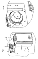
- Figures 1 and 2 show an inventive heater 1 with a housing 14. At the back there is a rear port 15 for a coaxial fresh air exhaust pipe. Figures 1 and 2 show the heater 1 with located on the heater 1 coaxial fresh air exhaust pipe 2 in 90 ° angle shape.
- Figure 3 shows the same heater according to the invention, in which, however, in contrast to Figures 1 and 2, the upwardly directed connection for the coaxial fresh air exhaust pipe 2 is closed by a cover 13.
- the heater 1 has a retaining strip 5 at the rear upper edge.
- a wall bracket 3 is attached on a wall 16.
- the wall mount 3 has an opening for receiving a coaxial fresh air exhaust pipe 2.
- a receiving strip 4 At the top of the wall mount 3 is a receiving strip 4.
- Figure 4 shows a section of Figure 3. It shows that the coaxial fresh air exhaust pipe 2 received in bends of the wall brackets 3 and fixed by means of a pipe clamp 9 with threaded pin 8.
- the heater 1 shows the heater 1 in section with its housing 14.
- the heater 1 is in the mounted state on the wall bracket 3.
- the coaxial fresh air exhaust pipe 2 has an inner exhaust pipe 10 and an outer fresh air pipe 11.
- the coaxial fresh air Exhaust pipe 2 is fixedly fixed within the wall bracket 3.
- the inner exhaust pipe 19 of the fresh air exhaust pipe 2 opens inside the device 1 in the heater exhaust pipe 12.
- the transition from the inner exhaust pipe 10 to the heater exhaust pipe 12 is sealed by a seal 7.
- the outer fresh air pipe 11 is sealed by a seal 6 to the housing 14 of the heater.
- From the heater exhaust pipe 12 is a line up to allow the connection of a coaxial fresh air exhaust pipe 2 analogous to Figures 1 and 2. According to FIG. 5, this connection is closed by a cover 13, so that neither exhaust gases escape upwards, nor fresh air can enter from above.
- the lid 13 is flush with the housing 14 and a seal 17 seals the exhaust port.
- the wall bracket 3 When connecting the fresh air exhaust pipe 2 through the wall bracket 3, the upper opening by means of the cover 13 as shown in Figure 5, closed.
- the wall bracket 3 is mounted on a wall 16 at the desired location.
- the coaxial fresh air exhaust pipe 2 is pushed through the wall 16 in the wall bracket 3, and fixed by means of a pipe clamp 9 with threaded pin 8.
- the heater 1 is then attached to the wall bracket 3.
- the heater 1 is bent at first angled with its retaining strip 5 on the receiving bar 4 of the wall bracket 3.
- the heater 1 is then aligned vertically, whereby the coaxial fresh air exhaust pipe 2 enters the rear receptacle 15 and in this case the inner exhaust pipe 10 with the heater exhaust pipe 12 is completed gas-tight and watertight by the circumferential seal 7.
- the outer fresh air pipe 11 of the coaxial fresh air exhaust pipe 2 with the housing 14 of the heater 1 by the circumferential seal 6 is gas-tight and watertight.
Landscapes
- Engineering & Computer Science (AREA)
- Mechanical Engineering (AREA)
- General Engineering & Computer Science (AREA)
- Housings, Intake/Discharge, And Installation Of Fluid Heaters (AREA)
- Incineration Of Waste (AREA)
Abstract
Description
- Die Erfindung bezieht sich auf ein Heizgerät mit rückseitigem Anschluss für ein koaxiales Frischluft-Abgas-Rohr.
- Die meisten Heizgeräte mit einem Anschluss für ein koaxiales Frischluft-Abgas-Rohr verfügen über einen Anschluss auf der Geräteoberseite. Beim Anschluss an eine Außenwandleitung oder an einen hinter dem Gerät befindlichen Kamin werden die Abgas- und Frischluftleitung in einer 90° Umlenkung zur Wand geführt.
- Der Erfindung liegt die Aufgabe zugrunde, einen unmittelbaren rückseitigen Anschluss eines koaxialen Abgasrohres ohne aufwändige Montagearbeiten zu ermöglichen. Insbesondere soll vermieden werden, dass zum Anschluss des rückseitigen Frischluft-Abgas-Rohres ein Öffnen des Gehäuses des Heizgerätes notwendig ist.
- Erfindungsgemäß wird dies gemäß den Merkmalen des Anspruchs 1 dadurch gelöst, dass das Heizgerät über einen rückseitigen Anschluss verfügt, welcher mit einer Wandhalterung, in welcher sich ein koaxiales Frischluft-Abgas-Rohr befindet, verbunden wird. Hierzu ist es lediglich notwendig, das Heizgerät mit seiner Halteleiste auf der Wandhalterung mit der korrespondierenden Aufnahmeleistung aufzusetzen und sodann das Heizgerät mit dem rückseitigen Anschluss über das in der Wandhalterung befindliche koaxiale Frischluft-Abgas-Rohr zu stülpen.
- Gemäß den Merkmalen des abhängigen Anspruchs 2 befindet sich in der rückseitigen Aufnahme im Heizgerät für das koaxiale Frischluft-Abgas-Rohr eine Dichtung für das Abgasrohr und/oder eine Dichtung für das Frischluft-Rohr, so dass eine gas- und wasserdichte Verbindung zwischen Gerät und koaxialem Frischluft-Abgas-Rohr hergestellt werden kann.
- Gemäß den Merkmalen des abhängigen Anspruchs 3 verfügt die Wandhalterung über Mittel zur Fixierung des koaxialen Frischluft-Abgas-Rohres. Vorzugsweise dienen hierzu Abwinkelungen in den Wandhalterungen, um welche eine Rohrschelle mit Gewindestift angeordnet ist. Das Frischluft-Abgas-Rohr kann in diese Mittel eingesteckt und sodann durch Zusammenziehen der Rohrschelle fixiert werden.
- Gemäß den Merkmalen des abhängigen Anspruchs 4 kann der rückseitige Anschluss für das koaxiale Frischluft-Abgas-Rohr mit einem Deckel verschlossen werden. Der Deckel schließt hierbei zugleich das Gehäuse des Heizgerätes ab, so dass auch der Frischluft-Anschluss abgedichtet ist. Damit die Abgase entweichen können und zugleich Frischluft angesaugt werden kann, befindet sich an der Oberseite des Gerätes eine Öffnung, die optional durch einen Deckel verschlossen ist, jedoch bei Bedarf geöffnet werden kann, so dass hier ein koaxiales Frischluft-Abgasrohr mit dem im Heizgerät befindlichen Heizgeräteabgasrohr verbunden werden kann und zugleich Frischluft in das Gehäuse des Gerätes gelangen kann. Hierdurch ist es möglich, auf den rückseitigen Anschluss des koaxialen Frischluft-Abgas-Rohres zu verzichten und das Heizgerät dann für den konventionellen Abtransport des Abgases nach oben sowie die Ansaugung von Frischluft von oben kommend einzustellen.
- Die Erfindung wird nun anhand der Figuren näher erläutert. Hierbei zeigen
- Fig. 1 ein erfindungsgemäßes Heizgerät von vorne,
- Fig. 2 dasselbe erfindungsgemäße Heizgerät von hinten,
- Fig. 3 das erfindungsgemäße Heizgerät bei der Montage an die an der Wand befindliche Wandhalterung,
- Fig. 4 einen Ausschnitt aus Figur 3 sowie
- Fig. 5 einen Querschnitt durch das erfindungsgemäße Heizgerät.
- Die Figuren 1 und 2 zeigen ein erfindungsgemäßes Heizgerät 1 mit einem Gehäuse 14. An der Rückseite befindet sich ein rückseitiger Anschluss 15 für ein koaxiales Frischluft-Abgas-Rohr. Die Figuren 1 und 2 zeigen das Heizgerät 1 mit auf dem Heizgerät 1 befindlichen koaxialen Frischluft-Abgas-Rohr 2 in 90°-Winkelform.
- Figur 3 zeigt dasselbe erfindungsgemäße Heizgerät, bei dem jedoch im Unterschied zu den Figuren 1 und 2 der nach oben gerichtete Anschluss für das koaxiale Frischluft-Abgas-Rohr 2 durch einen Deckel 13 verschlossen ist. Das Heizgerät 1 verfügt über eine Halteleiste 5 am hinteren oberen Rand. An einer Wand 16 ist eine Wandhalterung 3 befestigt. Die Wandhalterung 3 verfügt über eine Öffnung zur Aufnahme eines koaxialen Frischluft-Abgas-Rohres 2. Am oberen Rand der Wandhalterung 3 befindet sich eine Aufnahmeleiste 4. Figur 4 zeigt einen Ausschnitt aus Figur 3. Es zeigt, dass das koaxiale Frischluft-Abgas-Rohr 2 in Abwinkelungen der Wandhalterungen 3 aufgenommen und mittels einer Rohrschelle 9 mit Gewindestift 8 fest fixiert ist.
- Figur 5 zeigt das Heizgerät 1 im Schnitt mit seinem Gehäuse 14. Das Heizgerät 1 befindet sich im montierten Zustand an der Wandhalterung 3. Das koaxiale Frischluft-Abgas-Rohr 2 verfügt über ein inneres Abgasrohr 10 und ein äußeres Frischluftrohr 11. Das koaxiale Frischluft-Abgas-Rohr 2 befindet sich fest fixiert innerhalb der Wandhalterung 3. Das innere Abgasrohr 19 des Frischluft-Abgas-Rohres 2 mündet innerhalb des Gerätes 1 in das Heizgeräte-Abgas-Rohr 12. Der Übergang vom inneren Abgasrohr 10 zum Heizgeräte-Abgas-Rohr 12 ist durch eine Dichtung 7 abgedichtet. Das äußere Frischluft-Rohr 11 ist über eine Dichtung 6 zum Gehäuse 14 des Heizgerätes abgedichtet. Vom Heizgeräte-Abgas-Rohr 12 geht eine Leitung nach oben, um den Anschluss eines koaxialen Frischluft-Abgas-Rohres 2 analog Figuren 1 und 2 zu ermöglichen. Gemäß Figur 5 ist dieser Anschluss durch einen Deckel 13 verschlossen, so dass weder Abgase nach oben austreten, noch Frischluft von oben eintreten kann. Hierzu schließt der Deckel 13 bündig mit dem Gehäuse 14 ab und eine Dichtung 17 dichtet den Abgas-Anschluss.
- Zur Montage des Heizgerätes muss zunächst festgelegt werden, ob ein Abgas-Anschluss nach hinten oder nach oben gewünscht ist. Bei einem Anschluss nach oben wird der rückseitige Anschluss 15 mittels eines Deckels verschlossen und zugleich der nach oben gerichtet Anschluss geöffnet.
- Bei einem Anschluss des Frischluft-Abgas-Rohres 2 durch die Wandhalterung 3 wird die obere Öffnung mittels des Deckels 13 wie in Figur 5 dargestellt, verschlossen. Die Wandhalterung 3 wird an einer Wand 16 an der gewünschten Stelle montiert. Das koaxiale Frischluft-Abgas-Rohr 2 wird durch die Wand 16 in die Wandhalterung 3 geschoben, und mittels einer Rohrschelle 9 mit Gewindestift 8 fixiert. Das Heizgerät 1 wird sodann an der Wandhalterung 3 befestigt. Hierzu wird zunächst das Heizgerät 1 angewinkelt mit seiner Halteleiste 5 über die Aufnahmeleiste 4 der Wandhalterung 3 gestülpt. Das Heizgerät 1 wird sodann senkrecht ausgerichtet, wodurch das koaxiale Frischluft-Abgas-Rohr 2 in die rückseitige Aufnahme 15 gelangt und hierbei das innere Abgas-Rohr 10 mit dem Heizgeräte-Abgas-Rohr 12 durch die umlaufende Dichtung 7 gas- und wasserdicht abgeschlossen wird. Zugleich wird das äußere Frischluft-Rohr 11 des koaxialen Frischluft-Abgas-Rohres 2 mit dem Gehäuse 14 des Heizgerätes 1 durch die umlaufende Dichtung 6 gas- und wasserdicht abgeschlossen.
- Hierdurch ist es nicht notwendig, zum gas- und wasserdichten Anschluss des koaxialen Frischluft-Abgas-Rohres 2 das Gehäuse 14 des Heizgerätes 1 zu öffnen. Ein weiterer Vorteil des erfindungsgemäßen Heizgeräts 1 ist, dass auch an schwer zugänglichen Stellen eine einfache Montage möglich ist.
Claims (4)
- Heizgerät (1) mit Gehäuse (14) und rückseitigem Anschluss (15) für ein koaxiales Frischluft-Abgas-Rohr (2), bestehend aus einem inneren Abgasrohr (10) und einem äußeren Frischluftrohr (11), sowie einer Wandhalterung (3), dadurch gekennzeichnet, dass die Wandhalterung (3) eine Öffnung für ein koaxiales Frischluft-Abgas-Rohr (2) besitzt, das Heizgerät (1) rückseitige Aufnahmen für ein koaxiales Frischluft-Abgas-Rohr (2) besitzt, die Wandhalterung (3) über eine Aufnahmeleiste (4) verfügt und das Heizgerät (1) über eine hierzu korrespondierende Halteleiste (5) verfügt.
- Heizgerät (1) nach Anspruch 1, dadurch gekennzeichnet, dass die rückseitige Aufnahme im Heizgerät (1) für das koaxiales Frischluft-Abgas-Rohr (2) über eine Dichtung (7) zur Abdichtung des Abgasrohres (10) und / oder eine Dichtung (6) zur Abdichtung des Frischluftrohres (11) verfügt.
- Heizgerät nach Anspruch 1 oder 2, dadurch gekennzeichnet, dass die Wandhalterung (3) über Mittel zur Fixierung des koaxialen Frischluft-Abgas-Rohrs (2), vorzugsweise Abwinklungen, welche über eine Rohrschelle (9) mit Gewindestift (8) das Frischluftrohres (11) des koaxialen Frischluft-Abgas-Rohrs (2) fixieren, verfügt.
- Heizgerät (1) nach einem der Ansprüche 1 bis 3 im Heizgerät (1) verlaufenden Heizgeräteabgasrohr (12), dadurch gekennzeichnet, dass der rückseitige Anschluss (15) für ein koaxiales Frischluft-Abgas-Rohr (2) mit einem Deckel, der mit dem Gehäuse (14) des Heizgerätes (1) verbindbar ist, verschließbar ist und das Heizgeräteabgasrohr (12) im Heizgerät (1) über eine nach oben gerichtete Öffnung verfügt, die mittels eines mit dem Gehäuse (14) des Heizgerätes (1) verbindbaren Deckels (13) verschließbar ist.
Applications Claiming Priority (1)
| Application Number | Priority Date | Filing Date | Title |
|---|---|---|---|
| DE200620008322 DE202006008322U1 (de) | 2006-05-26 | 2006-05-26 | Heizgerät |
Publications (2)
| Publication Number | Publication Date |
|---|---|
| EP1860385A1 true EP1860385A1 (de) | 2007-11-28 |
| EP1860385B1 EP1860385B1 (de) | 2018-07-18 |
Family
ID=36974131
Family Applications (1)
| Application Number | Title | Priority Date | Filing Date |
|---|---|---|---|
| EP07009876.9A Active EP1860385B1 (de) | 2006-05-26 | 2007-05-18 | Heizgerät mit rückseitigem Anschluss für ein koaxiales Frischluf-Abgas-Rohr |
Country Status (4)
| Country | Link |
|---|---|
| EP (1) | EP1860385B1 (de) |
| DE (1) | DE202006008322U1 (de) |
| ES (1) | ES2690567T3 (de) |
| TR (1) | TR201814663T4 (de) |
Cited By (2)
| Publication number | Priority date | Publication date | Assignee | Title |
|---|---|---|---|---|
| EP2674675A1 (de) * | 2012-06-16 | 2013-12-18 | Vaillant GmbH | Abgasadapter für ein Heizgerät mit Rekuperator |
| US11421915B2 (en) | 2020-01-31 | 2022-08-23 | Rinnai America Corporation | Vent attachment for a tankless water heater |
Families Citing this family (1)
| Publication number | Priority date | Publication date | Assignee | Title |
|---|---|---|---|---|
| IT1392764B1 (it) * | 2009-01-28 | 2012-03-16 | Fonderie Sime S P A | Struttura di caldaia particolarmente per uso domestico |
Citations (6)
| Publication number | Priority date | Publication date | Assignee | Title |
|---|---|---|---|---|
| GB157868A (en) * | 1917-05-06 | 1921-09-22 | Sulzer Ag | Improvements in or relating to boilers for heating apparatus |
| GB1355055A (en) | 1970-10-16 | 1974-05-30 | Kayanson Engs Ltd | Improvements in or relating to flue outlets for stoves and boilers |
| GB2022792A (en) * | 1978-04-26 | 1979-12-19 | Bosch Gmbh Robert | Gas Fired Water Heater |
| EP0183607A1 (de) | 1984-11-19 | 1986-06-04 | Societe Industrielle Auer | Vorrichtung um ein gasdichtes Gasheizgerät mit der Aussenluft zu verbinden |
| DE19505053A1 (de) * | 1995-02-15 | 1996-08-22 | Bosch Siemens Hausgeraete | Warmwassergerät |
| FR2814797A1 (fr) * | 2000-09-29 | 2002-04-05 | Leblanc Sa E L M | Perfectionnements apportes aux appareils de chauffage tels que les chaudieres murales a ventouse |
-
2006
- 2006-05-26 DE DE200620008322 patent/DE202006008322U1/de not_active Expired - Lifetime
-
2007
- 2007-05-18 EP EP07009876.9A patent/EP1860385B1/de active Active
- 2007-05-18 ES ES07009876.9T patent/ES2690567T3/es active Active
- 2007-05-18 TR TR2018/14663T patent/TR201814663T4/tr unknown
Patent Citations (6)
| Publication number | Priority date | Publication date | Assignee | Title |
|---|---|---|---|---|
| GB157868A (en) * | 1917-05-06 | 1921-09-22 | Sulzer Ag | Improvements in or relating to boilers for heating apparatus |
| GB1355055A (en) | 1970-10-16 | 1974-05-30 | Kayanson Engs Ltd | Improvements in or relating to flue outlets for stoves and boilers |
| GB2022792A (en) * | 1978-04-26 | 1979-12-19 | Bosch Gmbh Robert | Gas Fired Water Heater |
| EP0183607A1 (de) | 1984-11-19 | 1986-06-04 | Societe Industrielle Auer | Vorrichtung um ein gasdichtes Gasheizgerät mit der Aussenluft zu verbinden |
| DE19505053A1 (de) * | 1995-02-15 | 1996-08-22 | Bosch Siemens Hausgeraete | Warmwassergerät |
| FR2814797A1 (fr) * | 2000-09-29 | 2002-04-05 | Leblanc Sa E L M | Perfectionnements apportes aux appareils de chauffage tels que les chaudieres murales a ventouse |
Cited By (3)
| Publication number | Priority date | Publication date | Assignee | Title |
|---|---|---|---|---|
| EP2674675A1 (de) * | 2012-06-16 | 2013-12-18 | Vaillant GmbH | Abgasadapter für ein Heizgerät mit Rekuperator |
| US11421915B2 (en) | 2020-01-31 | 2022-08-23 | Rinnai America Corporation | Vent attachment for a tankless water heater |
| US12130053B2 (en) | 2020-01-31 | 2024-10-29 | Rinnai America Corporation | Hybrid tank and tankless water heating system |
Also Published As
| Publication number | Publication date |
|---|---|
| ES2690567T3 (es) | 2018-11-21 |
| DE202006008322U1 (de) | 2006-08-24 |
| TR201814663T4 (tr) | 2018-11-21 |
| EP1860385B1 (de) | 2018-07-18 |
Similar Documents
| Publication | Publication Date | Title |
|---|---|---|
| DE102006053208B4 (de) | Mauerkasten | |
| EP2397777B1 (de) | Gehäuseeinheit für eine Heizungsanlage | |
| WO2007134829A1 (de) | Einrichtung für dunstabzugshauben | |
| EP1860385A1 (de) | Heizgerät mit rückseitigem Anschluss für ein koaxiales Frischluf-Abgas-Rohr | |
| EP2885542B1 (de) | Gebläsevorrichtung mit integriertem krümmer für einen gasbrenner | |
| EP2241839A2 (de) | Komponent von Klimakanälen, Anordnung in Klimakanälen und Verfahren zur Herstellung von einem Komponent von Klimakanälen, zur Wartung in Klimakanälen und zur Arbeit in Klimakanälen | |
| DE102011000654A1 (de) | Dunstabzugshaube für einen Herd, eine Kochstelle oder dergleichen | |
| EP2489914B1 (de) | Zuluft-Wanddurchführung | |
| DE102008059936A1 (de) | Laufradgehäuse eines Abgasturboladers mit separater Gehäusewand | |
| DE202013103709U1 (de) | Lüftungssystem für Kraftstofftanks | |
| DE3004225C2 (de) | Dunstabzugshaube für Abluftbetrieb mit einer schlauchartigen Luftleitvorrichtung | |
| DE102011051103A1 (de) | Dunstabzugshaube für einen Herd oder eine Kochstelle | |
| EP2199682A1 (de) | Hausgerät mit einer Gasleitung | |
| DE19836840C1 (de) | Absauganlage für Kraftfahrzeugabgase | |
| DE202010004156U1 (de) | Saugdose für Zentralstaubsauger | |
| AT510038B1 (de) | Ausrüstungsteil für schornsteine oder rauchgasabzüge | |
| DE3703915C2 (de) | ||
| DE202013009129U1 (de) | Kanalsektion zur Anordnung in einem Rauchabzug für einen Kaminofen, sowie ein mit einer derartigen Kanalsektion ausgestatteter Kaminofen | |
| EP0982547B1 (de) | Dunstabzugshauben-Verbindungsvorrichtung | |
| EP2055398A2 (de) | Mobiler Abzug | |
| WO2007006278A1 (de) | Kraftfahrzeugheizung und abgasleitungsdurchführung | |
| DE7802038U1 (de) | Dunstabzugshaube | |
| DE202013003254U1 (de) | Schrägdachhaube zum Anschluss von Dunst- und Lüftungsrohrleitungen | |
| DE9209873U1 (de) | Heizeinrichtung | |
| DE10013199A1 (de) | Rohrbelüftungsventil |
Legal Events
| Date | Code | Title | Description |
|---|---|---|---|
| PUAI | Public reference made under article 153(3) epc to a published international application that has entered the european phase |
Free format text: ORIGINAL CODE: 0009012 |
|
| AK | Designated contracting states |
Kind code of ref document: A1 Designated state(s): AT BE BG CH CY CZ DE DK EE ES FI FR GB GR HU IE IS IT LI LT LU LV MC MT NL PL PT RO SE SI SK TR |
|
| AX | Request for extension of the european patent |
Extension state: AL BA HR MK YU |
|
| 17P | Request for examination filed |
Effective date: 20071213 |
|
| AKX | Designation fees paid |
Designated state(s): AT BE BG CH CY CZ DE DK EE ES FI FR GB GR HU IE IS IT LI LT LU LV MC MT NL PL PT RO SE SI SK TR |
|
| STAA | Information on the status of an ep patent application or granted ep patent |
Free format text: STATUS: EXAMINATION IS IN PROGRESS |
|
| 17Q | First examination report despatched |
Effective date: 20161216 |
|
| GRAP | Despatch of communication of intention to grant a patent |
Free format text: ORIGINAL CODE: EPIDOSNIGR1 |
|
| STAA | Information on the status of an ep patent application or granted ep patent |
Free format text: STATUS: GRANT OF PATENT IS INTENDED |
|
| RIC1 | Information provided on ipc code assigned before grant |
Ipc: F24H 9/06 20060101AFI20180201BHEP Ipc: F23J 13/04 20060101ALI20180201BHEP |
|
| INTG | Intention to grant announced |
Effective date: 20180220 |
|
| GRAS | Grant fee paid |
Free format text: ORIGINAL CODE: EPIDOSNIGR3 |
|
| GRAA | (expected) grant |
Free format text: ORIGINAL CODE: 0009210 |
|
| STAA | Information on the status of an ep patent application or granted ep patent |
Free format text: STATUS: THE PATENT HAS BEEN GRANTED |
|
| AK | Designated contracting states |
Kind code of ref document: B1 Designated state(s): AT BE BG CH CY CZ DE DK EE ES FI FR GB GR HU IE IS IT LI LT LU LV MC MT NL PL PT RO SE SI SK TR |
|
| REG | Reference to a national code |
Ref country code: GB Ref legal event code: FG4D Free format text: NOT ENGLISH |
|
| REG | Reference to a national code |
Ref country code: CH Ref legal event code: EP |
|
| REG | Reference to a national code |
Ref country code: IE Ref legal event code: FG4D Free format text: LANGUAGE OF EP DOCUMENT: GERMAN |
|
| REG | Reference to a national code |
Ref country code: DE Ref legal event code: R096 Ref document number: 502007016287 Country of ref document: DE |
|
| REG | Reference to a national code |
Ref country code: AT Ref legal event code: REF Ref document number: 1019794 Country of ref document: AT Kind code of ref document: T Effective date: 20180815 |
|
| REG | Reference to a national code |
Ref country code: ES Ref legal event code: FG2A Ref document number: 2690567 Country of ref document: ES Kind code of ref document: T3 Effective date: 20181121 Ref country code: NL Ref legal event code: MP Effective date: 20180718 |
|
| REG | Reference to a national code |
Ref country code: LT Ref legal event code: MG4D |
|
| PG25 | Lapsed in a contracting state [announced via postgrant information from national office to epo] |
Ref country code: NL Free format text: LAPSE BECAUSE OF FAILURE TO SUBMIT A TRANSLATION OF THE DESCRIPTION OR TO PAY THE FEE WITHIN THE PRESCRIBED TIME-LIMIT Effective date: 20180718 |
|
| REG | Reference to a national code |
Ref country code: SK Ref legal event code: T3 Ref document number: E 28531 Country of ref document: SK |
|
| PG25 | Lapsed in a contracting state [announced via postgrant information from national office to epo] |
Ref country code: PL Free format text: LAPSE BECAUSE OF FAILURE TO SUBMIT A TRANSLATION OF THE DESCRIPTION OR TO PAY THE FEE WITHIN THE PRESCRIBED TIME-LIMIT Effective date: 20180718 Ref country code: LT Free format text: LAPSE BECAUSE OF FAILURE TO SUBMIT A TRANSLATION OF THE DESCRIPTION OR TO PAY THE FEE WITHIN THE PRESCRIBED TIME-LIMIT Effective date: 20180718 Ref country code: IS Free format text: LAPSE BECAUSE OF FAILURE TO SUBMIT A TRANSLATION OF THE DESCRIPTION OR TO PAY THE FEE WITHIN THE PRESCRIBED TIME-LIMIT Effective date: 20181118 Ref country code: FI Free format text: LAPSE BECAUSE OF FAILURE TO SUBMIT A TRANSLATION OF THE DESCRIPTION OR TO PAY THE FEE WITHIN THE PRESCRIBED TIME-LIMIT Effective date: 20180718 Ref country code: GR Free format text: LAPSE BECAUSE OF FAILURE TO SUBMIT A TRANSLATION OF THE DESCRIPTION OR TO PAY THE FEE WITHIN THE PRESCRIBED TIME-LIMIT Effective date: 20181019 Ref country code: SE Free format text: LAPSE BECAUSE OF FAILURE TO SUBMIT A TRANSLATION OF THE DESCRIPTION OR TO PAY THE FEE WITHIN THE PRESCRIBED TIME-LIMIT Effective date: 20180718 Ref country code: BG Free format text: LAPSE BECAUSE OF FAILURE TO SUBMIT A TRANSLATION OF THE DESCRIPTION OR TO PAY THE FEE WITHIN THE PRESCRIBED TIME-LIMIT Effective date: 20181018 |
|
| PG25 | Lapsed in a contracting state [announced via postgrant information from national office to epo] |
Ref country code: LV Free format text: LAPSE BECAUSE OF FAILURE TO SUBMIT A TRANSLATION OF THE DESCRIPTION OR TO PAY THE FEE WITHIN THE PRESCRIBED TIME-LIMIT Effective date: 20180718 |
|
| REG | Reference to a national code |
Ref country code: DE Ref legal event code: R097 Ref document number: 502007016287 Country of ref document: DE |
|
| PG25 | Lapsed in a contracting state [announced via postgrant information from national office to epo] |
Ref country code: CZ Free format text: LAPSE BECAUSE OF FAILURE TO SUBMIT A TRANSLATION OF THE DESCRIPTION OR TO PAY THE FEE WITHIN THE PRESCRIBED TIME-LIMIT Effective date: 20180718 Ref country code: RO Free format text: LAPSE BECAUSE OF FAILURE TO SUBMIT A TRANSLATION OF THE DESCRIPTION OR TO PAY THE FEE WITHIN THE PRESCRIBED TIME-LIMIT Effective date: 20180718 Ref country code: EE Free format text: LAPSE BECAUSE OF FAILURE TO SUBMIT A TRANSLATION OF THE DESCRIPTION OR TO PAY THE FEE WITHIN THE PRESCRIBED TIME-LIMIT Effective date: 20180718 |
|
| PLBE | No opposition filed within time limit |
Free format text: ORIGINAL CODE: 0009261 |
|
| STAA | Information on the status of an ep patent application or granted ep patent |
Free format text: STATUS: NO OPPOSITION FILED WITHIN TIME LIMIT |
|
| PG25 | Lapsed in a contracting state [announced via postgrant information from national office to epo] |
Ref country code: DK Free format text: LAPSE BECAUSE OF FAILURE TO SUBMIT A TRANSLATION OF THE DESCRIPTION OR TO PAY THE FEE WITHIN THE PRESCRIBED TIME-LIMIT Effective date: 20180718 |
|
| 26N | No opposition filed |
Effective date: 20190423 |
|
| PG25 | Lapsed in a contracting state [announced via postgrant information from national office to epo] |
Ref country code: SI Free format text: LAPSE BECAUSE OF FAILURE TO SUBMIT A TRANSLATION OF THE DESCRIPTION OR TO PAY THE FEE WITHIN THE PRESCRIBED TIME-LIMIT Effective date: 20180718 |
|
| REG | Reference to a national code |
Ref country code: CH Ref legal event code: PL |
|
| PG25 | Lapsed in a contracting state [announced via postgrant information from national office to epo] |
Ref country code: CH Free format text: LAPSE BECAUSE OF NON-PAYMENT OF DUE FEES Effective date: 20190531 Ref country code: MC Free format text: LAPSE BECAUSE OF FAILURE TO SUBMIT A TRANSLATION OF THE DESCRIPTION OR TO PAY THE FEE WITHIN THE PRESCRIBED TIME-LIMIT Effective date: 20180718 Ref country code: LI Free format text: LAPSE BECAUSE OF NON-PAYMENT OF DUE FEES Effective date: 20190531 |
|
| REG | Reference to a national code |
Ref country code: BE Ref legal event code: MM Effective date: 20190531 |
|
| PG25 | Lapsed in a contracting state [announced via postgrant information from national office to epo] |
Ref country code: LU Free format text: LAPSE BECAUSE OF NON-PAYMENT OF DUE FEES Effective date: 20190518 |
|
| PG25 | Lapsed in a contracting state [announced via postgrant information from national office to epo] |
Ref country code: IE Free format text: LAPSE BECAUSE OF NON-PAYMENT OF DUE FEES Effective date: 20190518 |
|
| PG25 | Lapsed in a contracting state [announced via postgrant information from national office to epo] |
Ref country code: BE Free format text: LAPSE BECAUSE OF NON-PAYMENT OF DUE FEES Effective date: 20190531 |
|
| PG25 | Lapsed in a contracting state [announced via postgrant information from national office to epo] |
Ref country code: PT Free format text: LAPSE BECAUSE OF FAILURE TO SUBMIT A TRANSLATION OF THE DESCRIPTION OR TO PAY THE FEE WITHIN THE PRESCRIBED TIME-LIMIT Effective date: 20181118 |
|
| REG | Reference to a national code |
Ref country code: AT Ref legal event code: MM01 Ref document number: 1019794 Country of ref document: AT Kind code of ref document: T Effective date: 20190518 |
|
| PG25 | Lapsed in a contracting state [announced via postgrant information from national office to epo] |
Ref country code: AT Free format text: LAPSE BECAUSE OF NON-PAYMENT OF DUE FEES Effective date: 20190518 |
|
| PG25 | Lapsed in a contracting state [announced via postgrant information from national office to epo] |
Ref country code: CY Free format text: LAPSE BECAUSE OF FAILURE TO SUBMIT A TRANSLATION OF THE DESCRIPTION OR TO PAY THE FEE WITHIN THE PRESCRIBED TIME-LIMIT Effective date: 20180718 |
|
| PG25 | Lapsed in a contracting state [announced via postgrant information from national office to epo] |
Ref country code: HU Free format text: LAPSE BECAUSE OF FAILURE TO SUBMIT A TRANSLATION OF THE DESCRIPTION OR TO PAY THE FEE WITHIN THE PRESCRIBED TIME-LIMIT; INVALID AB INITIO Effective date: 20070518 Ref country code: MT Free format text: LAPSE BECAUSE OF FAILURE TO SUBMIT A TRANSLATION OF THE DESCRIPTION OR TO PAY THE FEE WITHIN THE PRESCRIBED TIME-LIMIT Effective date: 20180718 |
|
| PGFP | Annual fee paid to national office [announced via postgrant information from national office to epo] |
Ref country code: DE Payment date: 20240423 Year of fee payment: 18 |
|
| PGFP | Annual fee paid to national office [announced via postgrant information from national office to epo] |
Ref country code: ES Payment date: 20240603 Year of fee payment: 18 |
|
| PGFP | Annual fee paid to national office [announced via postgrant information from national office to epo] |
Ref country code: SK Payment date: 20240426 Year of fee payment: 18 |
|
| PGFP | Annual fee paid to national office [announced via postgrant information from national office to epo] |
Ref country code: FR Payment date: 20240522 Year of fee payment: 18 |
|
| PGFP | Annual fee paid to national office [announced via postgrant information from national office to epo] |
Ref country code: TR Payment date: 20240430 Year of fee payment: 18 |
|
| PGFP | Annual fee paid to national office [announced via postgrant information from national office to epo] |
Ref country code: IT Payment date: 20240529 Year of fee payment: 18 |
|
| REG | Reference to a national code |
Ref country code: DE Ref legal event code: R119 Ref document number: 502007016287 Country of ref document: DE |
|
| REG | Reference to a national code |
Ref country code: SK Ref legal event code: MM4A Ref document number: E 28531 Country of ref document: SK Effective date: 20250518 |
|
| PG25 | Lapsed in a contracting state [announced via postgrant information from national office to epo] |
Ref country code: SK Free format text: LAPSE BECAUSE OF NON-PAYMENT OF DUE FEES Effective date: 20250518 |
|
| PGFP | Annual fee paid to national office [announced via postgrant information from national office to epo] |
Ref country code: GB Payment date: 20260323 Year of fee payment: 20 |
|
| PG25 | Lapsed in a contracting state [announced via postgrant information from national office to epo] |
Ref country code: DE Free format text: LAPSE BECAUSE OF NON-PAYMENT OF DUE FEES Effective date: 20251202 |
|
| PG25 | Lapsed in a contracting state [announced via postgrant information from national office to epo] |
Ref country code: IT Free format text: LAPSE BECAUSE OF NON-PAYMENT OF DUE FEES Effective date: 20250518 |
|
| PG25 | Lapsed in a contracting state [announced via postgrant information from national office to epo] |
Ref country code: FR Free format text: LAPSE BECAUSE OF NON-PAYMENT OF DUE FEES Effective date: 20250531 |