EP1860457B1 - Unité visant la production d'un signal de transfert et dispositif de radar pour son utilisation - Google Patents
Unité visant la production d'un signal de transfert et dispositif de radar pour son utilisation Download PDFInfo
- Publication number
- EP1860457B1 EP1860457B1 EP07252143.8A EP07252143A EP1860457B1 EP 1860457 B1 EP1860457 B1 EP 1860457B1 EP 07252143 A EP07252143 A EP 07252143A EP 1860457 B1 EP1860457 B1 EP 1860457B1
- Authority
- EP
- European Patent Office
- Prior art keywords
- frequency
- signal
- transmission signal
- transmission
- generating unit
- Prior art date
- Legal status (The legal status is an assumption and is not a legal conclusion. Google has not performed a legal analysis and makes no representation as to the accuracy of the status listed.)
- Ceased
Links
- 230000005540 biological transmission Effects 0.000 title claims description 81
- 239000013598 vector Substances 0.000 claims description 28
- 238000001228 spectrum Methods 0.000 claims description 10
- 239000011159 matrix material Substances 0.000 claims description 9
- 238000006243 chemical reaction Methods 0.000 claims 2
- 230000008054 signal transmission Effects 0.000 claims 1
- 230000006870 function Effects 0.000 description 23
- 238000000034 method Methods 0.000 description 10
- 230000006835 compression Effects 0.000 description 6
- 238000007906 compression Methods 0.000 description 6
- 238000004364 calculation method Methods 0.000 description 2
- 239000000284 extract Substances 0.000 description 2
- 238000012545 processing Methods 0.000 description 2
- 238000005070 sampling Methods 0.000 description 2
- 230000003044 adaptive effect Effects 0.000 description 1
- 230000015572 biosynthetic process Effects 0.000 description 1
- 238000007796 conventional method Methods 0.000 description 1
- 238000009795 derivation Methods 0.000 description 1
- 238000013461 design Methods 0.000 description 1
- 238000001514 detection method Methods 0.000 description 1
- 238000011161 development Methods 0.000 description 1
- 238000001914 filtration Methods 0.000 description 1
- 230000008569 process Effects 0.000 description 1
- 230000009467 reduction Effects 0.000 description 1
- 238000003786 synthesis reaction Methods 0.000 description 1
- 230000009466 transformation Effects 0.000 description 1
Images

Classifications
-
- H—ELECTRICITY
- H03—ELECTRONIC CIRCUITRY
- H03C—MODULATION
- H03C1/00—Amplitude modulation
-
- G—PHYSICS
- G01—MEASURING; TESTING
- G01S—RADIO DIRECTION-FINDING; RADIO NAVIGATION; DETERMINING DISTANCE OR VELOCITY BY USE OF RADIO WAVES; LOCATING OR PRESENCE-DETECTING BY USE OF THE REFLECTION OR RERADIATION OF RADIO WAVES; ANALOGOUS ARRANGEMENTS USING OTHER WAVES
- G01S13/00—Systems using the reflection or reradiation of radio waves, e.g. radar systems; Analogous systems using reflection or reradiation of waves whose nature or wavelength is irrelevant or unspecified
- G01S13/02—Systems using reflection of radio waves, e.g. primary radar systems; Analogous systems
- G01S13/06—Systems determining position data of a target
- G01S13/08—Systems for measuring distance only
- G01S13/10—Systems for measuring distance only using transmission of interrupted, pulse modulated waves
- G01S13/26—Systems for measuring distance only using transmission of interrupted, pulse modulated waves wherein the transmitted pulses use a frequency- or phase-modulated carrier wave
- G01S13/28—Systems for measuring distance only using transmission of interrupted, pulse modulated waves wherein the transmitted pulses use a frequency- or phase-modulated carrier wave with time compression of received pulses
-
- G—PHYSICS
- G01—MEASURING; TESTING
- G01S—RADIO DIRECTION-FINDING; RADIO NAVIGATION; DETERMINING DISTANCE OR VELOCITY BY USE OF RADIO WAVES; LOCATING OR PRESENCE-DETECTING BY USE OF THE REFLECTION OR RERADIATION OF RADIO WAVES; ANALOGOUS ARRANGEMENTS USING OTHER WAVES
- G01S7/00—Details of systems according to groups G01S13/00, G01S15/00, G01S17/00
- G01S7/02—Details of systems according to groups G01S13/00, G01S15/00, G01S17/00 of systems according to group G01S13/00
- G01S7/023—Interference mitigation, e.g. reducing or avoiding non-intentional interference with other HF-transmitters, base station transmitters for mobile communication or other radar systems, e.g. using electro-magnetic interference [EMI] reduction techniques
-
- G—PHYSICS
- G01—MEASURING; TESTING
- G01S—RADIO DIRECTION-FINDING; RADIO NAVIGATION; DETERMINING DISTANCE OR VELOCITY BY USE OF RADIO WAVES; LOCATING OR PRESENCE-DETECTING BY USE OF THE REFLECTION OR RERADIATION OF RADIO WAVES; ANALOGOUS ARRANGEMENTS USING OTHER WAVES
- G01S7/00—Details of systems according to groups G01S13/00, G01S15/00, G01S17/00
- G01S7/02—Details of systems according to groups G01S13/00, G01S15/00, G01S17/00 of systems according to group G01S13/00
- G01S7/28—Details of pulse systems
- G01S7/282—Transmitters
Definitions
- the present invention relates to a transmission signal generating unit and a radar transmission device using the same.
- Japanese Patent Publication Laid-open No. H4-357485 shows a radar signal processing device employing a pulse compression method.
- This radar signal processing device transmits a chirp signal (liner FM modulated signal) as a transmission signal to a relatively moving target, receives a signal reflected by the moving target as a received signal, then extracts Doppler components due to the movement of the target from the received signal, and detects the moving target based on the Doppler components.
- a chirp signal liner FM modulated signal
- a modulated long pulse is transmitted and after the reception a short pulse is obtained with its signal to noise ratio (SNR) improved by a pulse compression filter suitable for the modulated long pulse.
- SNR signal to noise ratio
- This method has many advantages such as the extension of detection range, the achievement of high range-resolution ability, and the reduction of interference signals. Thus, the method is applied to many radars.
- GB2334392 describes tracking a centre frequency.
- EP0250048 describes a frequency domain block adaptive digital filter.
- US5140332 describes a short pulse radar system with a long pulse transmitter.
- WO94/01933 describes a digital filter having high accuracy and efficiency.
- a chirp signal or a phase code modulated signal is used as a transmission signal. These signals have low side-lobes after pulse compression, but their spectrum widths are wide and many spurious components are included.
- An object of the present invention is to provide a transmission signal generating unit and a radar transmission device using the same which enable to suppress spurious components of a transmission signal and achieve the maximum signal level of a center frequency of the transmission signal.
- N x represents the range of frequency sample points around the centre frequency
- N represents the effective data that is in the central area of the sampled data of the transmission pulse
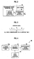
- Fig. 1 shows the schema of a radar device employing the transmission signal generating unit according to the embodiment of the present invention.
- the radar device comprises a transmission signal generating unit 10, a D/A converter 11, a local oscillator 12, a transmitting side mixer 13, a transmission signal amplifier 14, a circulator 15, an antenna 16, a received signal amplifier 17, a receiving side mixer 18, an A/D converter 19, a pulse compressor 20, a frequency analyzer 21, and a target detector 22.
- the transmission signal generating unit 10 generates a digital signal (pulse signal) as a transmission signal and transmits it to the D/A converter 11.
- the D/A converter 11 converts the transmission signal transmitted by the transmission signal generating unit 10 to an analog signal and transmits it to the transmitting side mixer 13.
- the local oscillator 12 generates a local signal having a local frequency and transmits it to the transmitting side mixer 13 and the receiving side mixer 18.
- the transmitting side mixer 13 mixes the transmission signal transmitted by the D/A converter 11 and the local signal transmitted by the local oscillator 12 to obtain a radio frequency signal and transmits it to the transmission signal amplifier 14.
- the transmission signal amplifier 14 amplifies the radio frequency signal transmitted by the transmitting side mixer 13 to a predetermined signal level and transmits it to the circulator 15.
- the circulator 15 switches between the first operation that outputs the radio frequency signal transmitted by the transmission signal amplifier 14 to the antenna 16 and the second operation that outputs a received signal received by the antenna 16 to the received signal amplifier 17.
- the antenna 16 such as an array antenna, transmits the radio frequency signal, transmitted by the transmission signal amplifier 14 through the circulator 15, toward a target. Also, the antenna 16 receives a reflected wave from the target and then transmits it to the circulator 15 as a received signal.
- the received signal amplifier 17 amplifies the received signal, received from the antenna 16 through the circulator 15, with a low noise and transmits it to the receiving side mixer 18.
- the receiving side mixer 18 converts the received signal received from the received signal amplifier 17 to an intermediate frequency signal (IF signal) by mixing the received signal and the local signal received from the local oscillator 12 and transmits it to the A/D converter 19.
- the A/D converter 19 converts the IF signal transmitted by the receiving side mixer 18 to a digital signal and transmits it to the pulse compressor 20.
- the frequency analyzer 21 performs Fourier transformation on a signal compressed by the pulse compressor 20 to transform data from time-domain to frequency-domain. Then, the received signal is decomposed to detect the relative speed of the target.
- the target detector 22 extracts Doppler components from the decomposed components, which represent the speed components of the target, to detect the target.
- Fig. 2 shows the structure of the transmission signal generating unit 10 in detail.
- the transmission signal generating unit 10 comprises a window function calculator 31 and a transmission signal generator 32.
- the window function calculator 31 generates a window function H that makes all frequencies without a center frequency of an input signal (phase-modulated rectangular pulse) and its adjacent frequencies zero and that makes the SNR of the center frequency maximum, and transmits the generated window function H to the transmission signal generator 32.
- the detail of the window function calculator 31 will be explained later.
- the transmission signal generator 32 generates a transmission signal by modulating the amplitude of the input signal using the window function H transmitted by the window function calculator 31.
- y y 1 y 2 ⁇ y N 1
- This spectrum pattern vector y comprises outputs at respective frequencies (discrete sample points) on a frequency space.
- S is a steering vector showing the center frequency.
- K is the number representing the main lobe (i.e. center frequency) of a frequency filter to be observed, and therefore the other frequency sample points are supposed as side-lobes.
- This window function H has a filter band width corresponding to the number of effective data set initially and makes the SNR maximum under the side-lobe free condition. It is clear that above calculations do not use any convergence method.
- the window function H obtained above it is possible to generate a transmission signal where the SNR of the center frequency of the input signal is made maximum and the spurious components of the input signal are reduced. That is, according to the transmission signal generating unit 10, since the signal loss of the center frequency is made minimum, the signal level can be ensured and the frequency band can be narrowed.
- the waveform of the input signal formed with the data number N f including a predetermined center frequency is defined as an original waveform and further the original waveform is defined as the steering vector S.
- the window function H is applied to generate the weighted vector W corresponding to the transmission signal. It is however possible to store the window function H that is pre-calculated in the above steps in a memory unit (not shown).
- the transmission signal generating unit 10 comprises: the window function calculator 31 that calculates a window function that makes all frequencies without a center frequency of an input signal and its adjacent frequencies zero and makes the SNR of the center frequency maximum; and the transmission signal generator 32 that generates a transmission signal whose amplitude is modulated in a shape of an envelope curve.
- Fig. 4 shows the structure of a radar transmission device which is applied with the transmission signal generating unit according to the present embodiment.
- a radar transmission device 40 comprises an intermediate frequency signal (IF signal) generating unit 10a as the transmission signal generating unit 10 in Fig. 1 , a local signal generator 34 (same as the local oscillator 12) that generates a local signal, a frequency converter 33, and a high-frequency signal transmitter 35.
- the frequency converter 33 frequency-converts (up-convert) an output signal from the IF signal generating unit 10a, using the local signal, to a frequency signal having a higher frequency than that of the output signal.
- the high-frequency signal transmitter 35 transmits the frequency signal frequency-converted by the frequency converter 33.
- the radar transmission device 40 is applied with the transmission signal generating unit 10a according to the present embodiment. Thus, it generates a transmission signal by modulating the amplitude of an input signal based on a window function that makes, for the input signal, all of the outer frequencies excluding a center frequency and its adjacent frequencies zero and at the same time makes the SNR of the center frequency maximum. It is therefore possible to suppress spurious components and to make the signal level of the center frequency maximum.
- Such radar transmission device is applicable to transmission units of radar systems, and so on.
Landscapes
- Engineering & Computer Science (AREA)
- Radar, Positioning & Navigation (AREA)
- Remote Sensing (AREA)
- Computer Networks & Wireless Communication (AREA)
- Physics & Mathematics (AREA)
- General Physics & Mathematics (AREA)
- Radar Systems Or Details Thereof (AREA)
- Transmitters (AREA)
Claims (6)
- Unité de génération de signaux de transmission (10), comprenant :un calculateur de fonction de fenêtrage (31) destiné à être appliqué à un signal d'entrée échantillonné, lequel génère une fonction de fenêtrage selon la formule H = u*{(uTu*)-1}uT, où u = Q̂QmQ̂Q, dans laquelle


avec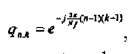


où k est le nombre représentant le lobe principal d'un filtre de fréquence à observer, Nx représente la plage de points d'échantillonnage de fréquence autour de la fréquence centrale, N représente les données efficaces situées dans la zone centrale des données échantillonnées de l'impulsion de transmission, et m et N sont choisis de sorte que 2m + N = Nf ; etun générateur de signaux de transmission (32) qui génère un signal de transmission dont l'amplitude est modulée sur la base de la fonction de fenêtrage générée par le calculateur de fonction de fenêtrage (31). - Unité de génération de signaux de transmission (10) selon la revendication 1, dans laquelle
le signal d'entrée est un signal d'onde continue à modulation d'impulsion présentant une fréquence prédéterminée qui est la même fréquence que celle du lobe principal. - Unité de génération de signaux de transmission (10) selon la revendication 2, dans laquelle
le générateur de signaux de transmission (32) génère une chaîne d'impulsions à modulation d'amplitude sous la forme du signal de transmission, chaque impulsion présentant une phase modulée. - Unité de génération de signaux de transmission (10) selon la revendication 1, dans laquelle
le signal d'entrée est un signal d'impulsion à modulation de fréquence incluant le lobe principal. - Unité de génération de signaux de transmission (10) selon la revendication 4, dans laquelle
la modulation de fréquence est obtenue en utilisant un signal modulé en fréquence. - Dispositif de transmission radar, comprenant :l'unité de génération de signaux de transmission (10) selon la revendication 1 ;une unité de conversion de fréquence (33) qui convertit la fréquence d'un signal de sortie de l'unité de génération de signaux de transmission en un signal de fréquence doté d'une fréquence supérieure à celle du signal de sortie, en utilisant un signal local ;une unité de transmission de signaux qui transmet le signal de fréquence converti en fréquence par l'unité de conversion de fréquence (33).
Applications Claiming Priority (1)
| Application Number | Priority Date | Filing Date | Title |
|---|---|---|---|
| JP2006145733 | 2006-05-25 |
Publications (3)
| Publication Number | Publication Date |
|---|---|
| EP1860457A2 EP1860457A2 (fr) | 2007-11-28 |
| EP1860457A3 EP1860457A3 (fr) | 2008-02-20 |
| EP1860457B1 true EP1860457B1 (fr) | 2013-06-26 |
Family
ID=38283872
Family Applications (1)
| Application Number | Title | Priority Date | Filing Date |
|---|---|---|---|
| EP07252143.8A Ceased EP1860457B1 (fr) | 2006-05-25 | 2007-05-24 | Unité visant la production d'un signal de transfert et dispositif de radar pour son utilisation |
Country Status (2)
| Country | Link |
|---|---|
| US (1) | US7839953B2 (fr) |
| EP (1) | EP1860457B1 (fr) |
Families Citing this family (2)
| Publication number | Priority date | Publication date | Assignee | Title |
|---|---|---|---|---|
| US8666253B2 (en) | 2008-05-13 | 2014-03-04 | Lockheed Martin Corporation | Radio frequency photonic transceiver |
| US8063817B2 (en) * | 2009-08-27 | 2011-11-22 | Honeywell International Inc. | Method for cross-range enhancement of real-beam radar imagery |
Family Cites Families (16)
| Publication number | Priority date | Publication date | Assignee | Title |
|---|---|---|---|---|
| JPS5234647A (en) | 1975-09-12 | 1977-03-16 | Hitachi Ltd | Frequency sampling filter |
| US4438413A (en) * | 1981-05-29 | 1984-03-20 | Motorola Inc. | Serial minimum shift keyed modulator including notch and bandpass filters |
| US4580139A (en) * | 1983-06-22 | 1986-04-01 | The United States Of America As Represented By The Secretary Of The Army | Waveform design for optimized ambiguity response |
| NL8601604A (nl) | 1986-06-20 | 1988-01-18 | Philips Nv | Frequentie-domein blok-adaptief digitaal filter. |
| US5140332A (en) | 1989-07-13 | 1992-08-18 | Westinghouse Electric Corp. | Short pulse radar system with a long pulse transmitter |
| JP2642803B2 (ja) | 1990-08-30 | 1997-08-20 | 三菱電機株式会社 | パルス・ドップラーレーダ装置 |
| JP3636361B2 (ja) | 1992-07-07 | 2005-04-06 | レイク・テクノロジイ・リミテッド | 高精度及び高効率を有するディジタルフィルタ |
| KR19990069891A (ko) | 1998-02-13 | 1999-09-06 | 전주범 | 적응 회귀 디지털 필터 알고리즘을 이용한 중심 주파수 추적 방법 |
| JP4116241B2 (ja) | 2000-12-14 | 2008-07-09 | 株式会社東芝 | パルスデータ生成方法、シェイプデータ生成方法、パルスデータ生成装置、シェイプデータ生成装置及び送信パルス信号生成装置 |
| WO2004077775A1 (fr) | 2003-02-25 | 2004-09-10 | Yokohama Tlo Company, Ltd. | Procede pour produire des formes d'impulsion |
| US7151484B2 (en) | 2003-09-30 | 2006-12-19 | Kabushiki Kaisha Toshiba | Pulse compression processor |
| JP4444057B2 (ja) | 2003-09-30 | 2010-03-31 | 株式会社東芝 | パルス圧縮処理装置 |
| TWI278444B (en) | 2004-02-16 | 2007-04-11 | Otsuka Chemical Co Ltd | Rust inhibitor composition |
| JP4199144B2 (ja) | 2004-03-11 | 2008-12-17 | 株式会社東芝 | ウェイト関数生成装置、参照信号生成装置、送信信号生成装置、信号処理装置及びアンテナ装置 |
| US7702502B2 (en) * | 2005-02-23 | 2010-04-20 | Digital Intelligence, L.L.C. | Apparatus for signal decomposition, analysis and reconstruction |
| JP4444150B2 (ja) | 2005-03-31 | 2010-03-31 | 株式会社東芝 | フィルタ装置 |
-
2007
- 2007-05-22 US US11/751,979 patent/US7839953B2/en active Active
- 2007-05-24 EP EP07252143.8A patent/EP1860457B1/fr not_active Ceased
Also Published As
| Publication number | Publication date |
|---|---|
| EP1860457A2 (fr) | 2007-11-28 |
| EP1860457A3 (fr) | 2008-02-20 |
| US7839953B2 (en) | 2010-11-23 |
| US20070273577A1 (en) | 2007-11-29 |
Similar Documents
| Publication | Publication Date | Title |
|---|---|---|
| US9194947B1 (en) | Radar system using matched filter bank | |
| US10365349B2 (en) | Radar device | |
| US6646587B2 (en) | Doppler radar apparatus | |
| JP5704552B2 (ja) | レーダ装置 | |
| JP2016151425A (ja) | レーダ装置 | |
| KR20190085492A (ko) | 위상을 검출하는 집적된 멀티 채널 rf 회로 | |
| EP1521097B1 (fr) | Processeur pour compression d'impulsions | |
| US20250231284A1 (en) | Radar device | |
| US5568150A (en) | Method and apparatus for hybrid analog-digital pulse compression | |
| US20230176184A1 (en) | Phased array frequency modulated continuous wave radar with non-uniform signal delay | |
| JP4444057B2 (ja) | パルス圧縮処理装置 | |
| US7561100B2 (en) | Correlation processor for receiver | |
| EP1860457B1 (fr) | Unité visant la production d'un signal de transfert et dispositif de radar pour son utilisation | |
| JP5075475B2 (ja) | 送信信号発生器及びそれを用いたレーダ送信装置 | |
| CN115128550A (zh) | 一种新型调频连续波联合雷达通信方法 | |
| EP1635192B1 (fr) | Appareil radar avec correction de la composante continue | |
| JP6688977B2 (ja) | レーダ装置 | |
| US20230408671A1 (en) | System and method for fast frequency hopping waveforms with continuous phase modulation in radar systems | |
| JP6220138B2 (ja) | 積分装置 | |
| Lota et al. | Low computational sensing with goertzel filtering for mobile industrial iot devices | |
| Petrov et al. | Phase modulated FMCW waveforms and receiver structures for automotive MIMO radars | |
| EP4603867A1 (fr) | Dispositif radar et procédé de traitement de signal radar | |
| JP7341372B2 (ja) | 信号処理装置、信号処理方法及びレーダ装置 | |
| US20250172679A1 (en) | Transceiving method of signals and radar apparatus | |
| An et al. | Wideband Dechirp Beamformer for Hyperbolic Frequency Modulation Waveforms |
Legal Events
| Date | Code | Title | Description |
|---|---|---|---|
| PUAI | Public reference made under article 153(3) epc to a published international application that has entered the european phase |
Free format text: ORIGINAL CODE: 0009012 |
|
| 17P | Request for examination filed |
Effective date: 20070601 |
|
| AK | Designated contracting states |
Kind code of ref document: A2 Designated state(s): AT BE BG CH CY CZ DE DK EE ES FI FR GB GR HU IE IS IT LI LT LU LV MC MT NL PL PT RO SE SI SK TR |
|
| AX | Request for extension of the european patent |
Extension state: AL BA HR MK YU |
|
| PUAL | Search report despatched |
Free format text: ORIGINAL CODE: 0009013 |
|
| RIC1 | Information provided on ipc code assigned before grant |
Ipc: H03H 21/00 20060101ALI20071219BHEP Ipc: G01S 13/00 20060101AFI20070814BHEP |
|
| AK | Designated contracting states |
Kind code of ref document: A3 Designated state(s): AT BE BG CH CY CZ DE DK EE ES FI FR GB GR HU IE IS IT LI LT LU LV MC MT NL PL PT RO SE SI SK TR |
|
| AX | Request for extension of the european patent |
Extension state: AL BA HR MK YU |
|
| 17Q | First examination report despatched |
Effective date: 20080915 |
|
| AKX | Designation fees paid |
Designated state(s): DE FI FR |
|
| REG | Reference to a national code |
Ref country code: DE Ref legal event code: R079 Ref document number: 602007031233 Country of ref document: DE Free format text: PREVIOUS MAIN CLASS: G01S0013000000 Ipc: G01S0013280000 |
|
| GRAP | Despatch of communication of intention to grant a patent |
Free format text: ORIGINAL CODE: EPIDOSNIGR1 |
|
| RIC1 | Information provided on ipc code assigned before grant |
Ipc: H03C 1/00 20060101ALI20121127BHEP Ipc: G01S 7/02 20060101ALI20121127BHEP Ipc: G01S 7/282 20060101ALI20121127BHEP Ipc: G01S 13/28 20060101AFI20121127BHEP |
|
| GRAS | Grant fee paid |
Free format text: ORIGINAL CODE: EPIDOSNIGR3 |
|
| GRAA | (expected) grant |
Free format text: ORIGINAL CODE: 0009210 |
|
| AK | Designated contracting states |
Kind code of ref document: B1 Designated state(s): DE FI FR |
|
| REG | Reference to a national code |
Ref country code: DE Ref legal event code: R096 Ref document number: 602007031233 Country of ref document: DE Effective date: 20130822 |
|
| PG25 | Lapsed in a contracting state [announced via postgrant information from national office to epo] |
Ref country code: FI Free format text: LAPSE BECAUSE OF FAILURE TO SUBMIT A TRANSLATION OF THE DESCRIPTION OR TO PAY THE FEE WITHIN THE PRESCRIBED TIME-LIMIT Effective date: 20130626 |
|
| PLBE | No opposition filed within time limit |
Free format text: ORIGINAL CODE: 0009261 |
|
| STAA | Information on the status of an ep patent application or granted ep patent |
Free format text: STATUS: NO OPPOSITION FILED WITHIN TIME LIMIT |
|
| 26N | No opposition filed |
Effective date: 20140327 |
|
| REG | Reference to a national code |
Ref country code: DE Ref legal event code: R097 Ref document number: 602007031233 Country of ref document: DE Effective date: 20140327 |
|
| REG | Reference to a national code |
Ref country code: FR Ref legal event code: PLFP Year of fee payment: 10 |
|
| REG | Reference to a national code |
Ref country code: FR Ref legal event code: PLFP Year of fee payment: 11 |
|
| REG | Reference to a national code |
Ref country code: FR Ref legal event code: PLFP Year of fee payment: 12 |
|
| PGFP | Annual fee paid to national office [announced via postgrant information from national office to epo] |
Ref country code: DE Payment date: 20190514 Year of fee payment: 13 |
|
| PGFP | Annual fee paid to national office [announced via postgrant information from national office to epo] |
Ref country code: FR Payment date: 20190410 Year of fee payment: 13 |
|
| REG | Reference to a national code |
Ref country code: DE Ref legal event code: R119 Ref document number: 602007031233 Country of ref document: DE |
|
| PG25 | Lapsed in a contracting state [announced via postgrant information from national office to epo] |
Ref country code: FR Free format text: LAPSE BECAUSE OF NON-PAYMENT OF DUE FEES Effective date: 20200531 |
|
| PG25 | Lapsed in a contracting state [announced via postgrant information from national office to epo] |
Ref country code: DE Free format text: LAPSE BECAUSE OF NON-PAYMENT OF DUE FEES Effective date: 20201201 |