EP1860728A1 - Antenne et etiquette d identification par radiofrequence - Google Patents
Antenne et etiquette d identification par radiofrequence Download PDFInfo
- Publication number
- EP1860728A1 EP1860728A1 EP05720805A EP05720805A EP1860728A1 EP 1860728 A1 EP1860728 A1 EP 1860728A1 EP 05720805 A EP05720805 A EP 05720805A EP 05720805 A EP05720805 A EP 05720805A EP 1860728 A1 EP1860728 A1 EP 1860728A1
- Authority
- EP
- European Patent Office
- Prior art keywords
- antenna
- line
- rfid tag
- antenna element
- shape
- Prior art date
- Legal status (The legal status is an assumption and is not a legal conclusion. Google has not performed a legal analysis and makes no representation as to the accuracy of the status listed.)
- Withdrawn
Links
Images




Classifications
-
- H—ELECTRICITY
- H01—ELECTRIC ELEMENTS
- H01Q—ANTENNAS, i.e. RADIO AERIALS
- H01Q9/00—Electrically-short antennas having dimensions not more than twice the operating wavelength and consisting of conductive active radiating elements
- H01Q9/04—Resonant antennas
- H01Q9/16—Resonant antennas with feed intermediate between the extremities of the antenna, e.g. centre-fed dipole
- H01Q9/26—Resonant antennas with feed intermediate between the extremities of the antenna, e.g. centre-fed dipole with folded element or elements, the folded parts being spaced apart a small fraction of operating wavelength
-
- H—ELECTRICITY
- H01—ELECTRIC ELEMENTS
- H01Q—ANTENNAS, i.e. RADIO AERIALS
- H01Q1/00—Details of, or arrangements associated with, antennas
- H01Q1/12—Supports; Mounting means
- H01Q1/22—Supports; Mounting means by structural association with other equipment or articles
- H01Q1/2208—Supports; Mounting means by structural association with other equipment or articles associated with components used in interrogation type services, i.e. in systems for information exchange between an interrogator/reader and a tag/transponder, e.g. in Radio Frequency Identification [RFID] systems
-
- H—ELECTRICITY
- H01—ELECTRIC ELEMENTS
- H01Q—ANTENNAS, i.e. RADIO AERIALS
- H01Q1/00—Details of, or arrangements associated with, antennas
- H01Q1/36—Structural form of radiating elements, e.g. cone, spiral, umbrella; Particular materials used therewith
- H01Q1/38—Structural form of radiating elements, e.g. cone, spiral, umbrella; Particular materials used therewith formed by a conductive layer on an insulating support
-
- H—ELECTRICITY
- H01—ELECTRIC ELEMENTS
- H01Q—ANTENNAS, i.e. RADIO AERIALS
- H01Q15/00—Devices for reflection, refraction, diffraction or polarisation of waves radiated from an antenna, e.g. quasi-optical devices
- H01Q15/0006—Devices acting selectively as reflecting surface, as diffracting or as refracting device, e.g. frequency filtering or angular spatial filtering devices
- H01Q15/0093—Devices acting selectively as reflecting surface, as diffracting or as refracting device, e.g. frequency filtering or angular spatial filtering devices having a fractal shape
-
- H—ELECTRICITY
- H01—ELECTRIC ELEMENTS
- H01Q—ANTENNAS, i.e. RADIO AERIALS
- H01Q9/00—Electrically-short antennas having dimensions not more than twice the operating wavelength and consisting of conductive active radiating elements
- H01Q9/04—Resonant antennas
- H01Q9/16—Resonant antennas with feed intermediate between the extremities of the antenna, e.g. centre-fed dipole
- H01Q9/28—Conical, cylindrical, cage, strip, gauze, or like elements having an extended radiating surface; Elements comprising two conical surfaces having collinear axes and adjacent apices and fed by two-conductor transmission lines
-
- H—ELECTRICITY
- H01—ELECTRIC ELEMENTS
- H01Q—ANTENNAS, i.e. RADIO AERIALS
- H01Q9/00—Electrically-short antennas having dimensions not more than twice the operating wavelength and consisting of conductive active radiating elements
- H01Q9/04—Resonant antennas
- H01Q9/16—Resonant antennas with feed intermediate between the extremities of the antenna, e.g. centre-fed dipole
- H01Q9/28—Conical, cylindrical, cage, strip, gauze, or like elements having an extended radiating surface; Elements comprising two conical surfaces having collinear axes and adjacent apices and fed by two-conductor transmission lines
- H01Q9/285—Planar dipole
-
- H—ELECTRICITY
- H04—ELECTRIC COMMUNICATION TECHNIQUE
- H04B—TRANSMISSION
- H04B1/00—Details of transmission systems, not covered by a single one of groups H04B3/00 - H04B13/00; Details of transmission systems not characterised by the medium used for transmission
- H04B1/69—Spread spectrum techniques
- H04B1/713—Spread spectrum techniques using frequency hopping
- H04B1/715—Interference-related aspects
-
- H—ELECTRICITY
- H04—ELECTRIC COMMUNICATION TECHNIQUE
- H04B—TRANSMISSION
- H04B1/00—Details of transmission systems, not covered by a single one of groups H04B3/00 - H04B13/00; Details of transmission systems not characterised by the medium used for transmission
- H04B1/69—Spread spectrum techniques
- H04B1/713—Spread spectrum techniques using frequency hopping
- H04B1/715—Interference-related aspects
- H04B2001/7154—Interference-related aspects with means for preventing interference
Definitions
- the present invention relates to an antenna technique, and more particularly, to a technique for downsizing an antenna.
- An RFID (Radio Frequency Identification) technique is a technique for identifying a data carrier by using a radio wave without contact.
- a tag RFID tag
- RFID reader/writer a device in which an IC chip and an antenna are embedded
- the RFID tag make a communication by using a radio wave
- the RFID reader/writer reads information stored in the IC chip (RFID tag IC), whereby the object or the person is identified.
- Fig. 8 shows a second example of an antenna available to an RFID tag.
- This antenna is a fundamental loop antenna which is formed with an antenna line 102, and the entire circumference of which is 1 wavelength, and the RFID tag is configured by connecting this antenna to an RFID tag IC 10.
- the RFID tag becomes very large if the fundamental antenna such as a dipole antenna, a loop antenna, etc. is used unchanged. Therefore, the downsizing of the antenna is demanded for the RFID tag.
- Fig. 9 shows a third example of an antenna available to an RFID tag.
- This antenna is downsized by bending a pair of antenna lines 101, which forms the dipole antenna according to the first example shown in Fig. 7, in a shape meandering at a right angle.
- Patent Document 3 discloses, for example, as shown in Fig. 13, a loop antenna the line conductor of which is bent in the shape of a snowflake.
- An antenna comprised by an RFID tag is not only demanded to be small as described above, but also desired to reduce an antenna gain in order to obtain a long communication distance. Additionally, for an RFID tag, so-called a passive tag, which does not comprise a battery within the RFID tag itself, and uses a radio wave from an RFID reader/writer as a power source for its operations, an antenna having high impedance is demanded to obtain a high power source voltage.
- the antenna is downsized by making a conductor line, which is an antenna element, simply meander, degradations in a gain and impedance are caused in contradiction to the above described demands.
- An antenna according to one preferred embodiment of the present invention is characterized in that an antenna element is configured with a conductor line which meanders in a shape where a plurality of lines of the same shape, which are bent only at an obtuse angle, are provided in sequence, and solves the above described problems with this characteristic.
- the antenna element may configure a loop antenna, the maximum point of an electric current in the antenna element when a high-frequency signal is fed may be arranged closer to the feeding point of the antenna element than the voltage maximum point of the antenna element at the time of the feeding.
- an induction element which cancels the capacitive component of the feeding device feeding a high-frequency signal to the antenna element may be comprised at the feeding point of the antenna element, and the induction element may be formed with a conductor line in a shape where a plurality of lines of the same shape, which, are bent only at an obtuse angle, are provided in sequence.
- the dipole antenna is configured with the conductor line which meanders in a shape where a plurality of lines of the same shape, which are bent only at the obtuse angle, are provided in sequence.
- a loop antenna may be configured by replacing the straight line portions of the antenna line 102, which is bent along a fractal pattern as shown in Figs. 10 and 11, with lines bent at an obtuse angle. The pattern of the replaced antenna line 102 is no longer fractal.
- the line of the same shape shown in Fig. 2A namely, the line bent only at an obtuse angle such as 120° is adopted, and the antenna element is formed with the conductor line which meanders in a shape where a plurality of lines of the same shape as the adopted line are provided in sequence.
- a curve in the shape of a semicircle exemplified in Fig. 2B, or a curve in the shape of a sinusoidal wave of 1 period exemplified in Fig. 2C may be adopted instead of adopting the line of the above described shape.
- a line of combined shapes, which is exemplified in Fig. 2D such as a shape obtained by combining the semicircle of Fig. 2B and the sinusoidal, wave of Fig. 2C may be adopted.
- the 1-waveiength loop antenna shown in Fig. 8 is desirable as an RFID tag because its impedance is high (normally on the order of 300 ⁇ ).
- the conventional loop antenna formed by bending the line conductor as exemplified in Fig. 13 a feeding point 12a at which an RFID tag is connected, and a point 12b which is the position of a 1/2 wavelength from the feeding point 12a are far apart in the antenna line 12.
- a high-frequency current becomes the maximum both at the feeding point 12a and the point 12b in the antenna line 12. If these 2 points are far apart, the impedance is degraded to on the order of several tens of ⁇ .
- the loop antenna the entire circumference length of which is nearly 1 wavelength is configured by making the feeding point 12a and the point 12b close and arranging them, and this antenna is used for the RFID tag.
- the linkage between the line in the vicinity of the feeding point 12a and that in the vicinity of the point 12b becomes strong, thereby improving the impedance.
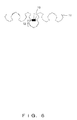
- FIG. 6 is a schematic showing an example where such an induction element 13 is inserted in parallel to the RFID tag IC 10 arranged at the feeding point in the dipole antenna, exemplified in Fig. 1.
- the induction element 13 is formed with a conductor line in a shape where a plurality of lines of the same shape, which are bent only at an obtuse angle, are provided in sequence similar to the antenna element 11. Accordingly, also for this induction element 13, its energy loss becomes small.
Landscapes
- Engineering & Computer Science (AREA)
- Computer Networks & Wireless Communication (AREA)
- Signal Processing (AREA)
- Details Of Aerials (AREA)
- Variable-Direction Aerials And Aerial Arrays (AREA)
- Support Of Aerials (AREA)
Applications Claiming Priority (1)
| Application Number | Priority Date | Filing Date | Title |
|---|---|---|---|
| PCT/JP2005/004549 WO2006098004A1 (fr) | 2005-03-15 | 2005-03-15 | Antenne et etiquette d’identification par radiofrequence |
Publications (2)
| Publication Number | Publication Date |
|---|---|
| EP1860728A1 true EP1860728A1 (fr) | 2007-11-28 |
| EP1860728A4 EP1860728A4 (fr) | 2008-12-24 |
Family
ID=36991364
Family Applications (1)
| Application Number | Title | Priority Date | Filing Date |
|---|---|---|---|
| EP05720805A Withdrawn EP1860728A4 (fr) | 2005-03-15 | 2005-03-15 | Antenne et etiquette d identification par radiofrequence |
Country Status (5)
| Country | Link |
|---|---|
| US (1) | US7773045B2 (fr) |
| EP (1) | EP1860728A4 (fr) |
| JP (1) | JPWO2006098004A1 (fr) |
| CN (1) | CN101128956B (fr) |
| WO (1) | WO2006098004A1 (fr) |
Families Citing this family (6)
| Publication number | Priority date | Publication date | Assignee | Title |
|---|---|---|---|---|
| CN101228664B (zh) * | 2005-07-29 | 2011-04-06 | 富士通株式会社 | 射频标签和制造射频标签的方法 |
| JP5018884B2 (ja) * | 2007-07-18 | 2012-09-05 | 富士通株式会社 | 無線タグ及び無線タグの製造方法 |
| US20130249759A1 (en) * | 2010-11-26 | 2013-09-26 | Kyocera Corporation | Antenna, dipole antenna, and communication apparatus using the same |
| CN102509872A (zh) * | 2011-10-24 | 2012-06-20 | 无锡邦普氿顺微电子有限公司 | 一种uhf rfid电子标签天线 |
| JP6161487B2 (ja) * | 2013-09-24 | 2017-07-12 | 峰光電子株式会社 | 読み取りセンサー及び管理システム |
| DE112018000705T5 (de) | 2017-03-06 | 2019-11-14 | Cummins Filtration Ip, Inc. | Erkennung von echten filtern mit einem filterüberwachungssystem |
Family Cites Families (26)
| Publication number | Priority date | Publication date | Assignee | Title |
|---|---|---|---|---|
| US3716861A (en) * | 1971-03-22 | 1973-02-13 | J Root | Serpentine antenna mounted on a rotatable capacitive coupler |
| JPS6095711U (ja) | 1983-12-06 | 1985-06-29 | 日本電気株式会社 | キヤビテイバツクスロツトアンテナ |
| US6104349A (en) * | 1995-08-09 | 2000-08-15 | Cohen; Nathan | Tuning fractal antennas and fractal resonators |
| US6452553B1 (en) * | 1995-08-09 | 2002-09-17 | Fractal Antenna Systems, Inc. | Fractal antennas and fractal resonators |
| JP4067672B2 (ja) * | 1998-12-25 | 2008-03-26 | 松下電器産業株式会社 | アンテナ装置並びにそれを用いた無線装置及び無線中継装置 |
| JP2000349526A (ja) | 1999-06-08 | 2000-12-15 | Hideo Suyama | 内蔵アンテナ装置 |
| GB9913526D0 (en) * | 1999-06-10 | 1999-08-11 | Harada Ind Europ Limited | Multiband antenna |
| EP1223637B1 (fr) * | 1999-09-20 | 2005-03-30 | Fractus, S.A. | Antennes multiniveau |
| JP4160215B2 (ja) | 1999-09-29 | 2008-10-01 | カルソニックカンセイ株式会社 | 車両用空気調和装置 |
| GB2355116B (en) | 1999-10-08 | 2003-10-08 | Nokia Mobile Phones Ltd | An antenna assembly and method of construction |
| EP2051325A1 (fr) * | 2000-01-19 | 2009-04-22 | Fractus, S.A. | Lignes de transmission, résonateurs, filtres et éléments réseau passifs fractals et de remplissage de l'espace |
| EP1592083B1 (fr) | 2000-01-19 | 2013-04-03 | Fractus, S.A. | antennes miniatures de remplissage d'espace |
| JP4221878B2 (ja) | 2000-01-25 | 2009-02-12 | ソニー株式会社 | アンテナ装置 |
| US7190319B2 (en) * | 2001-10-29 | 2007-03-13 | Forster Ian J | Wave antenna wireless communication device and method |
| US6603440B2 (en) * | 2000-12-14 | 2003-08-05 | Protura Wireless, Inc. | Arrayed-segment loop antenna |
| US6642898B2 (en) * | 2001-05-15 | 2003-11-04 | Raytheon Company | Fractal cross slot antenna |
| CN100382385C (zh) * | 2001-10-16 | 2008-04-16 | 弗拉克托斯股份有限公司 | 加载天线 |
| WO2003038747A2 (fr) | 2001-10-29 | 2003-05-08 | Marconi Intellectual Property (Us) Inc | Dispositif de radiocommunications a antenne beverage, et procede correspondant |
| JP2003271912A (ja) * | 2002-03-14 | 2003-09-26 | Mitsubishi Materials Corp | Idタグ、idタグを有する集積回路用基板、この集積回路用基板の製造方法、及びid検出装置 |
| US6642893B1 (en) * | 2002-05-09 | 2003-11-04 | Centurion Wireless Technologies, Inc. | Multi-band antenna system including a retractable antenna and a meander antenna |
| US7057559B2 (en) * | 2002-07-23 | 2006-06-06 | Penn State Research Foundation | Fractile antenna arrays and methods for producing a fractile antenna array |
| JP3898598B2 (ja) * | 2002-08-26 | 2007-03-28 | 株式会社ヨコオ | 送受信モジュール |
| JP2004112044A (ja) | 2002-09-13 | 2004-04-08 | Furukawa Electric Co Ltd:The | ループアンテナ |
| US7336243B2 (en) * | 2003-05-29 | 2008-02-26 | Sky Cross, Inc. | Radio frequency identification tag |
| WO2005043680A1 (fr) * | 2003-10-22 | 2005-05-12 | Fractal Antenna Systems, Inc. | Systeme d'antenne pour identification de frequence radio |
| US6975277B2 (en) * | 2003-11-21 | 2005-12-13 | Kyocera Wireless Corp. | Wireless communications device pseudo-fractal antenna |
-
2005
- 2005-03-15 CN CN2005800487191A patent/CN101128956B/zh not_active Expired - Fee Related
- 2005-03-15 WO PCT/JP2005/004549 patent/WO2006098004A1/fr not_active Ceased
- 2005-03-15 JP JP2007507974A patent/JPWO2006098004A1/ja active Pending
- 2005-03-15 EP EP05720805A patent/EP1860728A4/fr not_active Withdrawn
-
2007
- 2007-09-12 US US11/898,425 patent/US7773045B2/en not_active Expired - Fee Related
Also Published As
| Publication number | Publication date |
|---|---|
| US20080012773A1 (en) | 2008-01-17 |
| CN101128956B (zh) | 2012-11-21 |
| US7773045B2 (en) | 2010-08-10 |
| WO2006098004A1 (fr) | 2006-09-21 |
| JPWO2006098004A1 (ja) | 2008-08-21 |
| EP1860728A4 (fr) | 2008-12-24 |
| CN101128956A (zh) | 2008-02-20 |
Similar Documents
| Publication | Publication Date | Title |
|---|---|---|
| EP2330684B1 (fr) | Étiquette rfid, jeu d'étiquettes rfid et système rfid | |
| JP5018884B2 (ja) | 無線タグ及び無線タグの製造方法 | |
| CN1815808B (zh) | 曲折线天线 | |
| CN101053115B (zh) | 天线和非接触型标签 | |
| JP4393228B2 (ja) | 小型アンテナ及びそれを備えた無線タグ | |
| KR100970072B1 (ko) | 태그 안테나, 및 태그 | |
| CA2938640C (fr) | Terminal de paiement electronique et dispositif de raccordement | |
| CN101714696B (zh) | 天线和读写器装置 | |
| JP2007096655A (ja) | Rfidタグ用アンテナおよびrfidタグ | |
| KR20080012883A (ko) | Rfid 안테나 | |
| JP2007019905A (ja) | アンテナ及びこれを搭載するrfid用タグ | |
| JP4226642B2 (ja) | Rfタグ及びrfタグを製造する方法 | |
| US7773045B2 (en) | Antenna and RFID tag | |
| KR20180131620A (ko) | Ic태그 및 ic태그의 제조 방법 | |
| AU2006346817A1 (en) | Antenna for near field and far field radio frequency identification | |
| JP2011095844A (ja) | 非接触電子装置 | |
| JP4676445B2 (ja) | アンテナ及びこれを搭載するrfid用タグ | |
| JP5218251B2 (ja) | Rfidタグ読取装置 | |
| JP2007081632A (ja) | 無線icタグ | |
| JP5187083B2 (ja) | Rfidタグ、rfidシステム及びrfidタグ製造方法 | |
| KR100924427B1 (ko) | 안테나, 및 rfid 태그 | |
| JP6746058B2 (ja) | 無線icタグ装置及び無線icタグ組込装置 | |
| EP4124994B1 (fr) | Étiquette rfid et élément d'antenne destiné à être utilisé dans une étiquette rfid | |
| KR100690849B1 (ko) | Uhf 대역 프린팅 안테나 | |
| JP4479765B2 (ja) | Rfidタグ |
Legal Events
| Date | Code | Title | Description |
|---|---|---|---|
| PUAI | Public reference made under article 153(3) epc to a published international application that has entered the european phase |
Free format text: ORIGINAL CODE: 0009012 |
|
| 17P | Request for examination filed |
Effective date: 20071010 |
|
| AK | Designated contracting states |
Kind code of ref document: A1 Designated state(s): DE FR GB |
|
| DAX | Request for extension of the european patent (deleted) | ||
| RBV | Designated contracting states (corrected) |
Designated state(s): DE FR GB |
|
| A4 | Supplementary search report drawn up and despatched |
Effective date: 20081124 |
|
| 17Q | First examination report despatched |
Effective date: 20090925 |
|
| STAA | Information on the status of an ep patent application or granted ep patent |
Free format text: STATUS: THE APPLICATION IS DEEMED TO BE WITHDRAWN |
|
| 18D | Application deemed to be withdrawn |
Effective date: 20161001 |