EP1860729A1 - Antenne de communication et perche avec une antenne intégrée - Google Patents
Antenne de communication et perche avec une antenne intégrée Download PDFInfo
- Publication number
- EP1860729A1 EP1860729A1 EP07252072A EP07252072A EP1860729A1 EP 1860729 A1 EP1860729 A1 EP 1860729A1 EP 07252072 A EP07252072 A EP 07252072A EP 07252072 A EP07252072 A EP 07252072A EP 1860729 A1 EP1860729 A1 EP 1860729A1
- Authority
- EP
- European Patent Office
- Prior art keywords
- antenna
- pole
- moving body
- array part
- communication
- Prior art date
- Legal status (The legal status is an assumption and is not a legal conclusion. Google has not performed a legal analysis and makes no representation as to the accuracy of the status listed.)
- Withdrawn
Links
- 238000004891 communication Methods 0.000 title claims abstract description 90
- 238000001514 detection method Methods 0.000 claims description 69
- 230000008901 benefit Effects 0.000 description 3
- 238000010586 diagram Methods 0.000 description 3
- 238000009434 installation Methods 0.000 description 3
- 101000911772 Homo sapiens Hsc70-interacting protein Proteins 0.000 description 2
- 238000000034 method Methods 0.000 description 2
- 230000010363 phase shift Effects 0.000 description 2
- 101000710013 Homo sapiens Reversion-inducing cysteine-rich protein with Kazal motifs Proteins 0.000 description 1
- 101000661807 Homo sapiens Suppressor of tumorigenicity 14 protein Proteins 0.000 description 1
- 101000585359 Homo sapiens Suppressor of tumorigenicity 20 protein Proteins 0.000 description 1
- 102100029860 Suppressor of tumorigenicity 20 protein Human genes 0.000 description 1
- 230000001678 irradiating effect Effects 0.000 description 1
- 238000007726 management method Methods 0.000 description 1
- 230000000644 propagated effect Effects 0.000 description 1
- 230000001902 propagating effect Effects 0.000 description 1
Images








Classifications
-
- H—ELECTRICITY
- H01—ELECTRIC ELEMENTS
- H01Q—ANTENNAS, i.e. RADIO AERIALS
- H01Q3/00—Arrangements for changing or varying the orientation or the shape of the directional pattern of the waves radiated from an antenna or antenna system
- H01Q3/26—Arrangements for changing or varying the orientation or the shape of the directional pattern of the waves radiated from an antenna or antenna system varying the relative phase or relative amplitude of energisation between two or more active radiating elements; varying the distribution of energy across a radiating aperture
-
- H—ELECTRICITY
- H01—ELECTRIC ELEMENTS
- H01Q—ANTENNAS, i.e. RADIO AERIALS
- H01Q1/00—Details of, or arrangements associated with, antennas
- H01Q1/12—Supports; Mounting means
- H01Q1/22—Supports; Mounting means by structural association with other equipment or articles
- H01Q1/2208—Supports; Mounting means by structural association with other equipment or articles associated with components used in interrogation type services, i.e. in systems for information exchange between an interrogator/reader and a tag/transponder, e.g. in Radio Frequency Identification [RFID] systems
- H01Q1/2216—Supports; Mounting means by structural association with other equipment or articles associated with components used in interrogation type services, i.e. in systems for information exchange between an interrogator/reader and a tag/transponder, e.g. in Radio Frequency Identification [RFID] systems used in interrogator/reader equipment
-
- H—ELECTRICITY
- H01—ELECTRIC ELEMENTS
- H01Q—ANTENNAS, i.e. RADIO AERIALS
- H01Q21/00—Antenna arrays or systems
- H01Q21/06—Arrays of individually energised antenna units similarly polarised and spaced apart
- H01Q21/20—Arrays of individually energised antenna units similarly polarised and spaced apart the units being spaced along or adjacent to a curvilinear path
Definitions
- the present disclosure relates to a communication antenna used in a tag communication device such as an RFID reader-writer and a pole that incorporates the communication antenna.
- a communication antenna used in an RFID reader-writer is used while mounted on a wall and generally a planar antenna is desirable.
- communication antennas are mounted on both sides of a conveyer in a factory, an article on the conveyer could collide with the communication antennas.
- a communication antenna is mounted on a dock door in a delivery station, a truck or other vehicles could collide with the communication antenna.
- a patch antenna is often used as this type of planar antenna.
- the width of beams of radio waves irradiated from a patch antenna is approximately 60 degrees. Thus, radio waves are unlikely to be propagated across an area wider than 60 degrees. It is difficult to communicate with RFID tags present in a wide area.
- Embodiments of the present invention provide a communication antenna that is communicable with RFID tags present in a wide area with a small number of antennas and a pole with a built-in antenna.
- One or more embodiments of the present invention provides a communication antenna used in a communication device for performing wireless communications with an RFID tag over radio waves, the communication antenna comprising: an antenna array part where a plurality of antenna elements are arranged on an arc; and a variable unit for making variable the phase and/or amplitude of a radio frequency signal supplied to each of the antenna elements.
- the communication antenna according to one or more embodiments of the present invention may be configured so that the direction of radio beams irradiated from the antenna array part is changed by shifting the phase of a radio frequency signal supplied to each of the antenna elements via the variable unit.
- the communication antenna may be configured to comprise a plurality of moving body detection sensors arranged in the direction the radio wave beams change, wherein the moving body detection sensor detects a moving body ahead of the antenna array part and the direction of the radio beams changes based on the result of detection.
- the communication antenna according to one or more embodiments of the present invention may be configured to expand the width of radio beams irradiated from the antenna array part by adjusting the amplitude of a radio frequency signal supplied to each of the antenna elements via the variable unit.
- the antenna array part may be configured by a patch antenna composed of a plurality of antenna elements.
- a patch antenna is a planar antenna where one surface is a metallic plate placed on a dielectric board and the other surface is a ground plate (metallic plate).
- a pole with a built-in antenna is a pole incorporating the communication antenna.
- the pole with a built-in antenna may be wherein, for example, the plurality of antenna elements of the communication antenna are arranged on an arc along the direction of the circumference of the pole.
- the wording "the plurality of antenna elements of the communication antenna are arranged on an arc" includes a condition where, in case the external shape of a member where a plurality of antenna elements are arranged is a curved surface, the antenna elements are arranged along the arc of the curved surface.
- the "pole” includes one with a variety of cross sections such as a circle, an ellipse, and a polygon.
- the wording "the plurality of antenna elements of the communication antenna are arranged on an arc along the direction of the circumference of the pole" includes a condition where, with a pole having a circular cross section, a plurality of antenna elements are arranged along the arc of the circle, and with a pole having an elliptical cross section, a plurality of antenna elements are arranged along the arc of the ellipse, and with a pole having a polygonal cross section, a plurality of antenna elements are arranged along the arc of a circle that is inscribed in the polygon.
- the "RFID tag” includes a passive-type RFID tag that does not have a power source such as a battery and whose circuit operates on the power transmitted over radio waves from a tag communication device such as an RFID reader-writer and performs wireless communications with the tag communication device, and an active-type RFID tag equipped with a power source such as a battery.
- the "tag communication device” may be any device capable of communicating with an RFID tag via radio waves and may be an RFID reader-writer, an RFID reader, or an RFID writer.
- One or more embodiments of the present invention may include one or more the following advantages.
- the antenna array part of the one or more embodiments of the present invention employs a configuration where a plurality of antenna elements are arranged on an arc.
- radio waves are also irradiated in the exact transverse direction of the antenna array part. This enables communications with an RFID tag positioned in the exact transverse direction.
- a communication antenna to communicate with the RFID tag can be omitted and thus a small number of antennas provide communications with RFID tags present in a wide area.
- the one or more embodiments of the present invention comprises the variable unit that makes variable the phase and/or amplitude of a radio frequency signal supplied to each of the antenna elements. It is thus possible to change the direction of radio beams irradiated from the antenna array part by shifting the phase of a radio frequency signal supplied to each antenna element via the variable unit, or making available communications with RFID tags present in a wider area by expanding the width of radio beams irradiated from the antenna array part by adjusting the amplitude of the radio frequency signal.
- FIG. 1 is a block diagram of a communication antenna to which the invention is applied.
- a communication antenna 1 is an antenna used in a tag communication device 3 such as an RFID reader-writer performing wireless communications with an RFID tag 2 over radio waves and includes an antenna array part 4 and a variable unit 5.
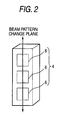
- the antenna array part 4 includes a plurality of antenna elements 6. The arrangement of the antenna elements 6 will be described later.
- variable phase shifter 7 and one variable attenuator 8 of the variable unit 5 are connected to a control circuit 9.
- the control circuit 9 outputs a control signal to the variable phase shifter 7 to shift the phase of a radio frequency signal supplied from the tag communication device 3 to the antenna element 6 via a combiner/distributer 10.
- the control circuit 9 outputs a control signal to the variable attenuator 8 to change the amplitude of a radio frequency signal supplied to the antenna element 6 as mentioned above.
- the communication antenna 1 is capable of changing radio beams irradiated from the antenna array part 4 into am arbitrary pattern by changing the phase and amplitude or only the amplitude of a radio frequency signal supplied to each antenna element 6 by way of the variable unit 5.
- the beam pattern of radio waves irradiated from the antenna array part 4 is changed as shown in Figs. 3(1) to (5) and the radio beam direction is changed.
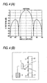
- Fig. 3(1) and Fig. 4(A) show a beam pattern assumed in case all antenna elements 6 transmit radio waves in the same phase.
- radio waves irradiated from the antenna array part 4 propagate as planar waves in a direction perpendicular to the arrangement of the antenna elements 6 as shown in Fig. 4 ( B) and Fig. 5(1).
- the phase of radio waves transmitted by each antenna element 6 should be shifted to each other so as to satisfy the expression given below.
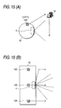
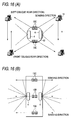
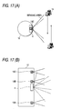
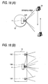
- Dotted lines in Fig. 4(B) and Figs. 5(1) to (5) show areas where communications with the RFID tag 2 are available. This is the same for Fig. 7 (B), Fig. 9, Fig. 12, and Figs. 14 to 18.
- the phase shift ⁇ k of the kth antenna element 6K with respect to the phase of the antenna element 6A as a reference is given by the following expression.
- the radio beam pattern changes as shown in Figs. 5(1) to (5) with the direction of the radio beam changed.
- an area where communications with the RFID tag 2 are available is expanded and communications with RFID tags 2 scattered in a wide range are made available with a single antenna.
- objects to be managed each having an RFID tag 2 attached thereon hereinafter referred to as the management object 11
- the management object 11 objects to be managed each having an RFID tag 2 attached thereon
- all RFID tags 2 are within the range of any beam pattern as shown in Fig. 5 so that no RFID tags 2 fail to communicate and communications with all RFID tags 2 are available.
- the beam pattern of radio waves irradiated from the antenna array part 4 is changed for example from one shown in Fig. 4 to one shown in Fig. 7 as the amplitude of a radio frequency signal supplied to each antenna element 6, and the beam width of the radio waves is expanded.
- the communication antenna 1 uses a wide beam pattern shown in Fig. 7. This expands the area where communications with the RFID tag 2 are available. This means that a single communication antenna 1 is capable of communicating with RFID tags 2 scattered in a wide range. In the example of Fig. 7, same as Fig. 5, a plurality of RFID tags are scattered in a wide vertical range. In this case also, all RFID tags 2 are within the range of any beam pattern as shown in Fig. 7 so that no RFID tags 2 fail to communicate and communications with all RFID tags 2 are available.
- Fig. 8 illustrates a specific configuration example of an antenna array part 4.
- the antenna array part 4 may be a patch antenna shown in Fig. 8 (A) .
- the width of the radio beams irradiated from the patch antenna is about 60 degrees so that the radio waves are not irradiated in the exact transverse direction.
- the radio waves are not irradiated in the exact transverse direction of the patch antenna (the exact transverse direction is +90 degrees and -90 degrees assuming the front of the antenna array part 4 is in the direction of 0 degrees) as understood from Fig. 8(C).
- the exact transverse direction is +90 degrees and -90 degrees assuming the front of the antenna array part 4 is in the direction of 0 degrees
- communications with an RFID tag positioned in the exact transverse direction are unavailable.
- the antenna array part 4 of Fig. 8(C) which is a patch antenna has a plurality of antenna elements 6 as components thereof arranged on an arc.
- Such an arc-shaped arrangement of the antenna elements 6 allows radio waves to be irradiated in the almost transverse direction of the antenna array part 4, thus expanding the range where communications with an RFID tag are available.
- the above arrangement of the antenna elements 6 is applicable to an antenna other than the patch antenna.
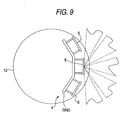
- the communication antenna 1 may be built into a pole 12 as shown in Fig. 9.
- a plurality of antenna elements 6 constituting the antenna array part 4 of the communication antenna 1 are arranged side by side on an arc along the direction of circumference of the pole 12.
- the pole 12 has a circular cross section so that the plurality of antenna elements 6 are arranged along the arc of the circle.
- the plurality of antenna elements may be arranged along the arc of the ellipse.
- An antenna element for the 900MHz band may be provided by a dielectric board 10cm by 10cm in vertical and horizontal size.
- a patch antenna composed of three antenna elements 6 shown in Fig. 9 is built into a pole 12, the pole 12 with a radius of 30cm is sufficient.
- the beam pattern of the radio waves irradiated from the antenna array part 4 is arbitrarily changed as shown in Figs. 5(1) to (5) so that the direction of the radio beams will be arbitrarily changed.
- a plurality of moving body detection sensors 13A, 13B, 13C may be arranged on the pole 12 in order to identify the range of an object of detection based on a detection signal from the plurality of moving body detection sensors 13A, 13B, 13C, and the beam patterns of the radio waves may be switched for the identified range.
- Fig. 10 a plurality of moving body detection sensors 13A, 13B, 13C
- the plurality of moving body detection sensors 13A, 13B, 13C are arranged in the direction the radio beams change (direction of height of the pole 12) and detect as a detection object a moving body 14 such as a forklift passing in the neighborhood of the pole 12, and outputs the detection signal to the control circuit 9.
- the control circuit 9 performs processing such as identification of the range of a detection object based on a detection signal coming from each of the moving body detection sensors 13A, 13B, 13C and switching between beam patterns of the radio waves for the identified range as a target.
- a same member as that in Fig. 1 is given a same sign and the detailed description of the same member is omitted.
- Fig. 11 is a flowchart of the operation to switch between beam patterns based on a detection signal from the moving body detection sensors 13A, 13B, 13C in the control circuit 9.
- the operation is started by a push on a monitor start button (not shown) .
- All the moving body detection sensors are place in the monitor state to monitor a moving body in front of the antenna array part (ST10).
- the control circuit 9 it is determined whether a third moving body detection sensor 13C, a second moving body detection sensor 13B, or a first moving body detection sensor 13A has detected a moving body in this order (ST11, ST12, ST13).
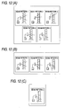
- the control circuit 9 it is determined whether a detection signal is inputted starting with the third moving body detection sensor 13C (ST11). In case a detection signal is inputted, there is a possibility of at least an RFID tag 2 being present in a position lower than the neighborhood of the installation position of the third moving body detection sensor 13C and selection is made between the beam patterns 1, 2, 3, 4 and 5 in Fig. 5 as shown in Fig. 12(A) in order to make available the communications with the RFID tag 2 in that position. As shown in ST20 to ST29 in Fig. 13, one of the beam patterns 1, 2, 3, 4 and 5 in Fig. 5 is sequentially selected and communications with the RFID tag 2 are made each time a new beam pattern is selected (Yes in ST11, ST14).
- a detection signal is not inputted from the third moving body detection sensor 13C in ST11, it is determined whether a detection signal is inputted from the second moving body detection sensor 13B (ST12).
- a detection signal is inputted, there is a possibility of at least an RFID tag 2 being present in a position lower than the neighborhood of the installation position of the second moving body detection sensor 13B and selection is made between the beam patterns 1, 4 and 5 in Fig. 5 as shown in Fig. 12(B) in order to make available the communications with the RFID tag 2 alone in that position.
- One of the beam patterns 1, 4 and 5 in Fig. 5 is selected as shown in Fig. 12(B). That is, selection is made sequentially between the beam patterns 1, 4 and 5 in Fig. 5 and communications with the RFID tag 2 are made each time a new beam pattern is selected (Yes in ST12, ST15).
- a detection signal is not inputted from the second moving body detection sensor 13B in ST12, it is determined whether a detection signal is inputted from the first moving body detection sensor 13A (ST13).
- a detection signal is inputted, there is a possibility of at least an RFID tag 2 being present in a position lower than the neighborhood of the installation position of the third moving body detection sensor 13A and only the beam pattern 5 in Fig. 5 is selected as shown in Fig. 12 (C) in order to make available the communications with the RFID tag 2 alone in that position.
- execution returns to the processing of ST11.
- Figs . 14 to 16 illustrate a pole incorporating a moving body detection sensor and a communication antenna.
- Fig. 14 shows an exemplary pole structure assuming a case where the incoming direction of a moving body is unknown.
- Fig. 15 illustrates an exemplary pole structure assuming a case where the incoming direction of a moving body is previously known as a specific direction.
- Fig. 16 illustrates an exemplary pole structure assuming a case where a moving body passes in front of and behind the pole.
- moving body detection sensors 13A, 13B, 13C are built into each of the right and left sides of the pole 12.
- the sensing direction of the moving body detection sensors 13A, 13B, 13C built into the left side of the pole 12 is the left oblique front direction as shown in Fig. 14 (A).
- the sensing direction of the moving body detection sensors 13A, 13B, 13C built into the right side of the pole is the right oblique front direction, opposite to that of the moving body detection sensors on the left side, as shown in Fig. 14(A).
- the moving body detection sensors 13A, 13B, 13C are built into only the left side of the pole 12 and the sensing direction of the moving body detection sensors 13A, 13B, 13C is set to the left oblique front direction.
- the moving body 14 passes in front of and behind the pole 12.
- another pair of right and left moving body detection sensors 13A, 13B, 13C shown in Fig. 14 is further installed.
- the sensing direction of the moving body detection sensors on the left side 13A, 13B, 13C is set to the left oblique rear direction as shown in Fig. 16(A).
- the sensing direction of the moving body detection sensors on the right side 13A, 13B, 13C is set to the right oblique rear direction, opposite to that of the moving body detection sensors on the left side 13A, 13B, 13C, as shown in Fig. 16 (A) .
- a communication antenna is separately provided on the rear side in addition to one on the front side in order to make available the communications with an RFID tag on a moving body 14 passing behind the pole 12.
- Figs. 17 and 18 illustrate the structure of a pole incorporating a moving body detection sensor and a communication antenna.
- Figs. 17 and 18 show an exemplary structure of a pole using a moving body detection sensor with a wide sensing range.
- the sensing direction of the exemplary structure in Fig. 17 and Fig. 18 of the moving body detection sensors 13A, 13B, 13C is a wide range from the sensing direction line of the moving body detection sensor 13C on the left side shown in Fig. 14 to the sensing direction line of the moving body detection sensor 13C on the right side.
- the exemplary pole structure of Figs. 17 and 18 by incorporating the moving body detection sensors 13A, 13B, 13C with such a wide sensing range in the front surface of the pole 12, any incoming moving body 14 from either the left or right direction of the front of the pole 12 can be detected with a singe moving body detection sensor, which simplifies the pole structure.
- a moving body detection sensor 13B is installed outside the area of the radio beams.
- the moving body detection sensor 13B may be arranged in front of the antenna array part 4 as shown in Fig. 18.
- Such an arrangement of the antenna array part 4 and the moving body detection sensor 13B is applicable to a moving body 14 passing in front of the pole 12 as well as a moving body 14 passing behind the pole 12 as shown in Fig. 16.
- control circuit 9 is provided on the side of the communication antenna 1 in Figs. 1 and 10, the control circuit 9 may be arranged on the side of the tag communication device 3. While the invention has been described with respect to a limited number of embodiments, those skilled in the art, having benefit of this disclosure, will appreciate that other embodiments can be devised which do not depart from the scope of the invention as disclosed herein. Accordingly, the scope of the invention should be limited only by the attached claims, as interpreted by the description and drawings.
Landscapes
- Near-Field Transmission Systems (AREA)
- Variable-Direction Aerials And Aerial Arrays (AREA)
- Waveguide Aerials (AREA)
Applications Claiming Priority (1)
| Application Number | Priority Date | Filing Date | Title |
|---|---|---|---|
| JP2006143203A JP2007318248A (ja) | 2006-05-23 | 2006-05-23 | 通信アンテナ及びアンテナ内蔵ポール |
Publications (1)
| Publication Number | Publication Date |
|---|---|
| EP1860729A1 true EP1860729A1 (fr) | 2007-11-28 |
Family
ID=38441742
Family Applications (1)
| Application Number | Title | Priority Date | Filing Date |
|---|---|---|---|
| EP07252072A Withdrawn EP1860729A1 (fr) | 2006-05-23 | 2007-05-21 | Antenne de communication et perche avec une antenne intégrée |
Country Status (4)
| Country | Link |
|---|---|
| US (1) | US20070273531A1 (fr) |
| EP (1) | EP1860729A1 (fr) |
| JP (1) | JP2007318248A (fr) |
| CN (1) | CN101079518A (fr) |
Families Citing this family (10)
| Publication number | Priority date | Publication date | Assignee | Title |
|---|---|---|---|---|
| CN101957925B (zh) * | 2010-06-11 | 2016-06-01 | 刘守兵 | 多单元组合天线阵列rfid定位识别系统 |
| US8963688B2 (en) * | 2012-08-20 | 2015-02-24 | The Goodyear Tire & Rubber Company | Stacked tire RFID reader system and method |
| CN103268640B (zh) * | 2013-05-10 | 2016-02-03 | 北京速通科技有限公司 | 基于多波束天线的多车道自由流电子收费系统及方法 |
| CN103745244B (zh) * | 2014-01-14 | 2017-03-08 | 公安部第三研究所 | 具有弧形读卡表面的射频识别读写器 |
| JP6216268B2 (ja) * | 2014-03-10 | 2017-10-18 | 日本ピラー工業株式会社 | アンテナ装置 |
| CN104269658B (zh) * | 2014-10-21 | 2016-04-27 | 内蒙古工业大学 | 用于mimo-sar成像的弧形阵列天线 |
| JP6741503B2 (ja) * | 2016-07-11 | 2020-08-19 | マスプロ電工株式会社 | 狭指向性アンテナ |
| JP7014343B2 (ja) * | 2019-10-24 | 2022-02-01 | 株式会社村田製作所 | Rfidリーダライタ用アンテナ装置 |
| US11398680B2 (en) * | 2020-05-22 | 2022-07-26 | Star Systems International Limited | Directional curved antenna |
| JP2025174076A (ja) * | 2024-05-16 | 2025-11-28 | 東芝テック株式会社 | 無線タグ通信装置、およびプログラム |
Citations (4)
| Publication number | Priority date | Publication date | Assignee | Title |
|---|---|---|---|---|
| EP0837523A2 (fr) * | 1996-10-18 | 1998-04-22 | Kabushiki Kaisha Toshiba | Antenne adaptative |
| WO2001095431A1 (fr) * | 2000-06-07 | 2001-12-13 | Siemens Aktiengesellschaft | Systeme d'antennes comportant au moins deux antennes pour un appareil d'ecriture-lecture |
| US20040201539A1 (en) * | 2003-04-09 | 2004-10-14 | Yewen Robert G. | Radio frequency identification system and antenna system |
| WO2005091435A1 (fr) * | 2004-03-19 | 2005-09-29 | Brother Kogyo Kabushiki Kaisha | Dispositif de communication sans fil par balises |
Family Cites Families (11)
| Publication number | Priority date | Publication date | Assignee | Title |
|---|---|---|---|---|
| US3268893A (en) * | 1963-10-08 | 1966-08-23 | Philco Corp | Angle measuring radar utilizing broad beam signal of known form and waveform recognition circuitry |
| JPS59178002A (ja) * | 1983-03-29 | 1984-10-09 | Radio Res Lab | 円偏波アンテナ |
| US5641141A (en) * | 1994-10-06 | 1997-06-24 | At&T Wireless Services, Inc. | Antenna mounting system |
| JPH09172505A (ja) * | 1995-12-21 | 1997-06-30 | Toshiba Corp | 患者監視システム及び患者監視方法 |
| US6151964A (en) * | 1998-05-25 | 2000-11-28 | Citizen Watch Co., Ltd. | Angular velocity sensing device |
| JP3788115B2 (ja) * | 1999-07-23 | 2006-06-21 | 松下電器産業株式会社 | アンテナ装置の製造方法 |
| US20050159187A1 (en) * | 2002-03-18 | 2005-07-21 | Greg Mendolia | Antenna system and method |
| US7187288B2 (en) * | 2002-03-18 | 2007-03-06 | Paratek Microwave, Inc. | RFID tag reading system and method |
| JP3854909B2 (ja) * | 2002-08-06 | 2006-12-06 | 株式会社日立製作所 | プラズマ処理装置 |
| US6999042B2 (en) * | 2003-03-03 | 2006-02-14 | Andrew Corporation | Low visual impact monopole tower for wireless communications |
| JP2006042268A (ja) * | 2004-07-30 | 2006-02-09 | Fujitsu Ltd | 電子タグ認証装置、および電子タグとの通信調整方法 |
-
2006
- 2006-05-23 JP JP2006143203A patent/JP2007318248A/ja active Pending
-
2007
- 2007-05-14 US US11/798,461 patent/US20070273531A1/en not_active Abandoned
- 2007-05-21 EP EP07252072A patent/EP1860729A1/fr not_active Withdrawn
- 2007-05-23 CN CNA2007101042529A patent/CN101079518A/zh active Pending
Patent Citations (4)
| Publication number | Priority date | Publication date | Assignee | Title |
|---|---|---|---|---|
| EP0837523A2 (fr) * | 1996-10-18 | 1998-04-22 | Kabushiki Kaisha Toshiba | Antenne adaptative |
| WO2001095431A1 (fr) * | 2000-06-07 | 2001-12-13 | Siemens Aktiengesellschaft | Systeme d'antennes comportant au moins deux antennes pour un appareil d'ecriture-lecture |
| US20040201539A1 (en) * | 2003-04-09 | 2004-10-14 | Yewen Robert G. | Radio frequency identification system and antenna system |
| WO2005091435A1 (fr) * | 2004-03-19 | 2005-09-29 | Brother Kogyo Kabushiki Kaisha | Dispositif de communication sans fil par balises |
Also Published As
| Publication number | Publication date |
|---|---|
| CN101079518A (zh) | 2007-11-28 |
| US20070273531A1 (en) | 2007-11-29 |
| JP2007318248A (ja) | 2007-12-06 |
Similar Documents
| Publication | Publication Date | Title |
|---|---|---|
| EP1860729A1 (fr) | Antenne de communication et perche avec une antenne intégrée | |
| EP2154552B1 (fr) | Dispositif de communication entre étiquettes et son procédé | |
| KR100979622B1 (ko) | Rf 태그 리더 및 방법 | |
| ES2341185T3 (es) | Metodo de deteccion del movimiento alrededor de puertas automaticas. | |
| JP4588220B2 (ja) | トランスポンダ | |
| US5214410A (en) | Location of objects | |
| EP2246934B1 (fr) | Antenne réseau, dispositif de communication d'étiquette, système de communication d'étiquette, et procédé de commande de faisceau pour une antenne réseau | |
| EP3238141B1 (fr) | Dispositifs rfid avec antennes à fréquences multiples | |
| EP3251170B1 (fr) | Antenne d'identification par radiofréquence (rfid) à l'infini | |
| JP5182548B2 (ja) | タグ通信装置 | |
| JP4618483B2 (ja) | 無線タグ通信システムの質問器及び無線タグ通信システム | |
| US8026848B2 (en) | Radio-based position location systems, antenna configurations, and methods for determining antenna configurations | |
| KR100879454B1 (ko) | 스위치를 이용한 rfid 안테나 및 상기 rfid안테나를 포함하는 장치 | |
| NL1028330C2 (nl) | Smart Shelf. | |
| CZ308229B6 (cs) | Simulátor cílů pro automobilové radary s řadou radiových transpondérů | |
| Hansen et al. | Method for controlling the angular extent of interrogation zones in RFID | |
| EP2639878B1 (fr) | Système d'étiquette RFID et dispositif de lecture/écriture RFID | |
| EP3926518B1 (fr) | Appareil et système de suppression des interférences | |
| JP4188305B2 (ja) | 監視装置、周囲監視システム、および車両 | |
| TW431078B (en) | Device for position determination by means of radio waves | |
| JP2004266549A (ja) | アンテナ装置 | |
| JP3277253B2 (ja) | 地上側の情報を移動体に伝送する伝送システム | |
| WO2008018253A1 (fr) | Dispositif de détection de la direction | |
| JP2005308678A (ja) | 侵入・障害物検出装置及び無給電応答装置 | |
| JP2006242960A (ja) | 侵入・障害物検出装置及び無給電応答装置 |
Legal Events
| Date | Code | Title | Description |
|---|---|---|---|
| PUAI | Public reference made under article 153(3) epc to a published international application that has entered the european phase |
Free format text: ORIGINAL CODE: 0009012 |
|
| AK | Designated contracting states |
Kind code of ref document: A1 Designated state(s): AT BE BG CH CY CZ DE DK EE ES FI FR GB GR HU IE IS IT LI LT LU LV MC MT NL PL PT RO SE SI SK TR |
|
| AX | Request for extension of the european patent |
Extension state: AL BA HR MK YU |
|
| 17P | Request for examination filed |
Effective date: 20080527 |
|
| AKX | Designation fees paid |
Designated state(s): AT BE BG CH CY CZ DE DK EE ES FI FR GB GR HU IE IS IT LI LT LU LV MC MT NL PL PT RO SE SI SK TR |
|
| STAA | Information on the status of an ep patent application or granted ep patent |
Free format text: STATUS: THE APPLICATION HAS BEEN WITHDRAWN |
|
| 18W | Application withdrawn |
Effective date: 20100805 |