EP1862767A2 - Sicherheits-Positionssensor für Zylinder, Zylinder mit einem solchen Positionssensor - Google Patents
Sicherheits-Positionssensor für Zylinder, Zylinder mit einem solchen Positionssensor Download PDFInfo
- Publication number
- EP1862767A2 EP1862767A2 EP07405110A EP07405110A EP1862767A2 EP 1862767 A2 EP1862767 A2 EP 1862767A2 EP 07405110 A EP07405110 A EP 07405110A EP 07405110 A EP07405110 A EP 07405110A EP 1862767 A2 EP1862767 A2 EP 1862767A2
- Authority
- EP
- European Patent Office
- Prior art keywords
- sensor
- cylinder
- piston
- reed
- magnet
- Prior art date
- Legal status (The legal status is an assumption and is not a legal conclusion. Google has not performed a legal analysis and makes no representation as to the accuracy of the status listed.)
- Granted
Links
Images


Classifications
-
- G—PHYSICS
- G01—MEASURING; TESTING
- G01D—MEASURING NOT SPECIALLY ADAPTED FOR A SPECIFIC VARIABLE; ARRANGEMENTS FOR MEASURING TWO OR MORE VARIABLES NOT COVERED IN A SINGLE OTHER SUBCLASS; TARIFF METERING APPARATUS; MEASURING OR TESTING NOT OTHERWISE PROVIDED FOR
- G01D5/00—Mechanical means for transferring the output of a sensing member; Means for converting the output of a sensing member to another variable where the form or nature of the sensing member does not constrain the means for converting; Transducers not specially adapted for a specific variable
- G01D5/02—Mechanical means for transferring the output of a sensing member; Means for converting the output of a sensing member to another variable where the form or nature of the sensing member does not constrain the means for converting; Transducers not specially adapted for a specific variable using mechanical means
- G01D5/06—Mechanical means for transferring the output of a sensing member; Means for converting the output of a sensing member to another variable where the form or nature of the sensing member does not constrain the means for converting; Transducers not specially adapted for a specific variable using mechanical means acting through a wall or enclosure, e.g. by bellows, by magnetic coupling
-
- G—PHYSICS
- G01—MEASURING; TESTING
- G01D—MEASURING NOT SPECIALLY ADAPTED FOR A SPECIFIC VARIABLE; ARRANGEMENTS FOR MEASURING TWO OR MORE VARIABLES NOT COVERED IN A SINGLE OTHER SUBCLASS; TARIFF METERING APPARATUS; MEASURING OR TESTING NOT OTHERWISE PROVIDED FOR
- G01D5/00—Mechanical means for transferring the output of a sensing member; Means for converting the output of a sensing member to another variable where the form or nature of the sensing member does not constrain the means for converting; Transducers not specially adapted for a specific variable
- G01D5/12—Mechanical means for transferring the output of a sensing member; Means for converting the output of a sensing member to another variable where the form or nature of the sensing member does not constrain the means for converting; Transducers not specially adapted for a specific variable using electric or magnetic means
- G01D5/25—Selecting one or more conductors or channels from a plurality of conductors or channels, e.g. by closing contacts
- G01D5/251—Selecting one or more conductors or channels from a plurality of conductors or channels, e.g. by closing contacts one conductor or channel
- G01D5/2515—Selecting one or more conductors or channels from a plurality of conductors or channels, e.g. by closing contacts one conductor or channel with magnetically controlled switches, e.g. by movement of a magnet
Definitions
- the invention relates to a sensor for monitoring a relative to the sensor translationally displaceable part with respect to its position on the displacement axis and a cylinder with such a sensor for monitoring the position of the piston with respect to its axis of movement.
- the invention relates to a safety position sensor for a pneumatic or a hydraulic cylinder and such a cylinder with the position sensor.
- Another object of the invention is the positioning of a sensor and the safe Fixing the sensor, for example, to achieve a cylinder in this position with technically simple means.
- a sensor for monitoring a relative to the sensor translationally displaceable part with respect to its position on the displacement axis is actuated by means of a displaceable part arranged with respect to north and south pole oriented in the direction of displacement magnet.
- it has three reed contacts arranged in parallel, of which a first and a second reed contact are arranged in one plane. They are arranged with their longitudinal axes parallel next to each other. By virtue of this arrangement, they can be actuated virtually simultaneously by the magnetic field of the magnet arranged on the displaceable part.
- the third reed contact is arranged at a distance from the plane of the first and second reed contact.
- Such a sensor, arranged with the third reed contact at a greater distance from the actuating magnet than the other two reed contacts, is safe from manipulation by external magnetic fields.
- An externally applied external magnetic field will always first actuate the third reed switch, which is closer to the externally applied magnet. It is practically impossible not to operate the arranged close to the first two reed contacts third reed contact when with an external magnetic field of the first and the second reed contact is actuated.
- Such a sensor is particularly suitable for detecting the position of a piston in a cylinder.
- the sensor is arranged on the cylinder, the made of non-magnetic material, such as aluminum, and the piston carries a magnet, preferably a magnetic ring around the piston.
- the third reed contact is expediently at most as sensitive as the two reed contacts that are arranged in parallel, so that it does not respond with a stronger magnetic field than this one. It is then the distance to the exciter magnet, the deciding factor.
- the sensor In order to make the range for a sensor signal more precise and to make the boundary between sensor signal exciting and no sensor signal exciting position of the magnet as short as possible, is at one end of the two same switching reed contacts, and preferably at both ends of the reed contacts, the sensor with a shield , in particular an iron part is equipped.
- This shield distorts the magnetic field of the exciter magnet, so that the magnetic field is deflected by the material of the shield from the area of the reed contacts.
- the magnetic field jumps with the one pole from the shield and with the other pole in the shielding, ie, if until then the field lines in the north were deformed by the shielding and the field lines in the south remained virtually undeformed, The deformation suddenly jumps over to the field lines of the South Pole, while the field lines of the North Pole remain largely undeformed. This achieves a clearer signal.
- the two-sided shield has the particular advantage that a direction reversed installation of the sensor is excluded. Alternatively, an unambiguous identification of the sensor and the position of the shielding can be provided.
- the senor is provided with a mounting tail at opposite ends.
- This mounting tail prevents each shift of the sensor from the tail end away, so that with two opposite mounting tails displacement in both directions is prevented.
- the fastening tail is provided with a toothing and the locking head with a latching in the toothing locking mechanism.
- the teeth and the locking mechanism cooperatively allow the attachment of the locking heads, but they prevent the removal of the once plugged locking head.
- Such serrations and locking mechanisms are known from cable ties ago.
- the latching mechanism can be released by means of a tool from the operative connection with the fastening tail.
- the simple and secure immovable positioning of a sensor for monitoring a relative to the sensor translationally displaceable part with respect to its position on the displacement axis, which is actuated by means of a displaceable part magnet is achieved according to the invention characterized in that the sensor is provided at opposite ends with a mounting tail is, and that two locking heads are provided.
- Each mounting tail is provided with a toothing and each locking head with a latching in the toothing locking mechanism, the cooperating the attachment of the locking heads allow the mounting tails, but prevent the removal of the once plugged locking head.
- the latching heads have a stop which, after assembly of the sensor, is e.g. to a cylinder, presses against an abutment surface of the cylinder so that the sensor is prevented by the one attachment tail from moving in one direction and is prevented from moving in the opposite direction with the other attachment tail.
- a stop of the locking heads can be connected via a thread with the locking mechanism of the locking heads, which thread extends in the longitudinal direction of the mounting tails.
- the stops must be permanently connected to the locking mechanism. A twisting of the stops around the thread axis must not lead to a release of the locking head from the fastening tail.
- the senor can be formed with two oppositely locking latching mechanisms, and the fixation of the sensor by inserting provided with stops and a toothing mounting tails. These are inserted from both sides into the two locking mechanisms.
- the attachment tails are designed such that they can be accommodated next to each other in a e.g. formed on the cylinder groove, and therefore can overlap each other in the longitudinal direction.
- the senor is characterized by a fastening device, which is designed to be cooperative or connected to the sensor. This prevents displacement of the sensor, in particular in the direction of displacement of the piston.
- the fastening device connects the sensor via a preferably releasable positive connection with a support for the sensor.
- a support for the sensor As a carrier, especially a wall of a cylinder is provided.
- the spring means are captive and hold the positive connection, e.g. between the fastening tail and the locking lip, or between a tooth and a recess pressed into the surface of the support, reliably upright.
- the sensor is preferably provided with a fastening device which has at least one tooth which can be pressed into the surface of a groove receiving the sensor. By this pressing a recess for the positive connection with the tooth can be achieved. Alternatively, however, it may also be e.g. a change in the surface of the carrier may be provided which has a series of recesses. In this case, the tooth engages in one of these recesses of R selectedung.
- the fastening device expediently comprises the sensor body. As a result, this is also positively connected to the fastening device.
- the fastening device can thus be a spring element released from the sensor.
- the fastening device can be produced in one piece from, for example, a spring steel strip which is designed to encompass the sensor body.
- at least two teeth are provided, which are brought into engagement with the surface of the groove in the carrier can.
- a flange 69 is also advantageously formed, which engages in the undercut of a T-shaped undercut groove.
- the invention also relates to a cylinder with a piston therein, wherein on the piston, a magnet is arranged, which is directed with the polarity in the direction of movement of the piston.
- a sensor for monitoring the position of the piston is arranged in the cylinder.
- the sensor is a sensor according to the invention.
- the sensor according to the invention ensures the monitoring of the piston position. It ensures safety by allowing two reed contacts to simultaneously respond to the magnetic field of the magnet and the third reed contact must not respond. The third reed contact is due to its greater distance from the magnet and piston in closer proximity to an externally acting external magnetic field.
- a groove in which the sensor is mounted displaceably in the direction of movement of the piston is advantageously formed a groove in which the sensor is mounted displaceably in the direction of movement of the piston.
- the sensor can be inserted from outside into this groove and brought into the desired position along the displacement direction possible therein.
- the sensor is advantageously designed as a cylindrical part (but not axially symmetric and therefore not circular cylindrical part, but preferably as a symmetrical to a mirror plane trained, rectangular parallelepiped) whose cylinder axis is parallel to the longitudinal direction of the reed contacts.
- a magnetic ring is formed around the piston so that the piston always exerts the same influence on the sensor independently of its rotational position about the piston axis.
- the core of the sensor 11 shown in Figure 1 is composed of a printed circuit board 13 and two first reed contacts 15,16 and a third reed contact 17.
- the first two reed contacts 15 and 16 are arranged in parallel closers.
- the third reed contact 17 is connected in series with the first reed contact 15 and an opener.
- the first two reed contact are below the printed circuit board 13 in a common plane and arranged side by side, that the connection points for the reed contacts are arranged in a rectangle.
- the third reed contact 17 is arranged above the printed circuit board 13 and parallel to it. Its connection points lie on two sides of the rectangle formed by the connection points of the first two reed contacts 15, 16.
- a metal rod is arranged as a magnetic shield 19.
- the spatial design of this shield is of minor importance.
- the longitudinal direction of the metal rod is aligned in the example perpendicular to the longitudinal direction of the reed contacts 15 and 16.
- the width of the metal rod is directed in the longitudinal direction of the reed contacts 15 and 16.
- This sensor body 21 has a T-shaped cross-section. Within the upwardly directed trunk of the T is the third reed contact 17, in the beam of the T, the printed circuit board and the two first reed contacts 15 and 16, and, if present, the shield 19 are arranged.
- the sensor body 21 is adapted in shape to the receiving device which is to receive the sensor.
- the illustrated cylindrical shape with the T-shaped cross-section is adapted to arrange the sensor longitudinally displaceable in a T-shaped undercut formed groove.
- the sensor 11 shown in Figure 3 with two of the locking head 23 shown in Figure 4 on the two mounting tails 25 is in different Positions in such a T-shaped undercut groove can be fixed.
- the sensor 11 has on the central sensor body 21 on the opposite, T-shaped end faces which are perpendicular to the longitudinal direction of the reed contacts, depending on a fastening tail 25. These are integrally molded with the sensor body 21. Connection cables 27 for the sensor exit from one of these end faces. These can, contrary to the illustration, also emerge on both end faces. The connection cables 27 can be guided through openings 29 in the latching head 23.
- a latching opening 31 is formed for the implementation of the fastening tail 25.
- a locking lip 33 is formed, which can go with the teeth 35 on the mounting tines 25 an engagement.
- a stop surface 37 is formed, which can cooperate with an end face of the groove forming wall.
- such a sensor 11 is arranged in a groove 41 in the wall of a cylinder 43.
- the piston 45 is mounted linearly movable in a cylinder chamber 47. It may be pushed back and forth by air, hydraulic oil or other medium, or it may move this medium by its e.g. motor-induced change of position.
- For the inlet and the outlet of the medium openings 46 are provided in the piston wall. This movement of the piston is transmitted with punch 48 from a motor to the piston or from the piston to, for example, a tool.
- an annular magnet 49 is arranged at the periphery of the piston 45.
- a field line 51 represents the local magnetic field of the magnet 49 schematically simplified.
- the piston is in the unsafe area B.
- the piston 45 is shown in the safe area A.
- the magnetic field of the magnet 49 is not strong enough to switch the reed contacts in the sensor 11. Only in a position in which the field lines extend through the reed contacts, the magnet is able to switch them.
- the first two reed contacts 15 and 16 are closer to the magnet. They therefore shield the outer third reed contact additionally.
- the magnetic lines extend as soon as they reach the area of the contact elements of the reed switch, concentrated through them and thereby excite in this the contact closing force.
- FIG. 8 shows the same situations as in FIGS. 5 and 7. It is the sensor 11 but provided with two shields 19. The field lines 51 are therefore distorted in both positions of the piston 45. There is therefore a safe position A in the region of the sensor 11. Outside this range, the piston 45 is in an unsafe position. The transition area between these areas is more accurate with the shield 19 than without this shielding.
- the sensor 11 is not formed with two mounting tails 25, but with two latching mechanisms, in particular two latching lips 33, for latching engagement in the teeth 35 of fixing members 53.
- These fixing parts 53 have a fastening tail 25 with a toothing 35 and an abutment head 55.
- the teeth of the fastening tail 25 engage in the latching lips on the sensor body 21. Since the standing in engagement with these mounting tails can not be pulled back, thereby the sensor body is fixed in position as soon as the two stop heads of the fixing members 53 are in abutment with the cylinder 43. So that the stop heads do not project beyond the length of the cylinder 43, the groove is widened at its end and the stopper heads 55 fit into the extended groove.
- the two lateral flanges 59 of the groove wall which form the undercut, cut at its end.
- the engagement can be solved with a tool.
- a tool For this purpose, either the locking lip 33 from the fastening tail 25 can be pressed away, or the fastening tail 25 of the latching lip 33 can be lifted.
- the latching lip 33 is resiliently connected to the sensor body 21 or formed on a resiliently connected to the sensor body 21 part.
- the mounting tails 25 are spring-supported relative to the groove 41. In any case, the intervention is maintained by spring means.
- FIG. 9 Another example of the secure attachment of the sensor 11 in the groove 41 of a cylinder 43 is shown in Figures 9 and 10.
- a fixing plate 61 is fixed, which consists of a harder material than the jacket of the cylinder, in which the T-shaped undercut groove 41 is formed.
- This disc 61 is provided with a thread into which a screw 65 is screwed.
- teeth 63 are formed. These teeth can by tightening the screw 65 in the material of the undercut of the groove 41 forming flanges 59th be pressed. The teeth are thus in engagement with the flange 59. It has formed such a positive connection.
- This disc is held by a spring 67 in this engagement taking position.
- the spring 67 may, as shown, be a coil spring, or else a leaf spring.
- the suspension can be provided between the sensor with mounting washer and the groove, or between the sensor body 21 and the mounting plate 61.
- the disc 61 may also be a leaf spring with teeth 63 and a thread and therefore take over the task of the disc and the spring simultaneously.
- a tool independent of the sensor can be used instead of the screw 65th
- the spring element shown in Figure 11 for mounting the sensor 11 in a T-shaped undercut groove 41 is made in one piece from a spring steel. It has a sensor body 21 peripheral part and a spring part with two teeth 63 which can be brought into engagement with a recess in the side wall of the groove, in particular the narrower and outer part of the T-shaped groove. These depressions can be achieved by pressing the tooth 63 into the aluminum of the piston skirt.
- the parts comprising the sensor body 21 lie in the mounted position between the sensor body and the flange 59. In addition, they can exert a spring force on the sensor which presses it against the bottom of the groove.
- the teeth 63 in the resilient part are pressed by the spring force of this part to the outside. They are in the relaxed state of the spring element at a greater distance from each other than the width of the groove. As a result, they must be approximated against each other during insertion of the spring element into the groove under deformation of the spring parts. With a screwdriver or a special tool, the punched out of the spring steel and folded teeth 63 can be pressed directly opposite each other in the aluminum of the flange 59 and therefore hold there form-fitting.
- FIG. 1 A variant of such a spring element is shown in FIG. This also has flanges 69, a part surrounding the sensor body and two spring parts with teeth 63. However, these are here in front of and behind the sensor.
- FIG. 13 shows four circuit diagrams in which the three reed contacts 15, 16, 17 are combined into two conductor tracks and can have three distinguishable switching patterns. Apart from these schematics, it is also possible to tap off the three reed contacts individually and to analyze the switching state of the sensor with a downstream logic.
- the first reed contact 15 and the third reed contact 17 are connected in series. In the series connection, it is necessary for the first reed contact to be a make contact and the third a normally closed contact to obtain a clear sensor signal.
- the second reed contact may be an opener (FIG. 13b) or a make contact (FIG. 13a).
- the first reed contact 15 and the third reed contact 17 are connected in parallel. This requires that the first reed contact 15 is an opener and the third reed contact 17 is a make contact, so that unique sensor signals are generated.
- the second reed contact can again be an opener or a closer.
- each reed contact can be an opener or a make contact independently of the other one.
- the logic circuit must be designed accordingly so that the open position and closed position of the individual reed contacts are interpreted correctly.
Landscapes
- Physics & Mathematics (AREA)
- General Physics & Mathematics (AREA)
- Measurement Of Length, Angles, Or The Like Using Electric Or Magnetic Means (AREA)
- Actuator (AREA)
- Switches That Are Operated By Magnetic Or Electric Fields (AREA)
Abstract
Description
- Die Erfindung betrifft einen Sensor zur Überwachung eines gegenüber dem Sensor translatorisch verschieblichen Teiles bezüglich seiner Position auf der Verschiebeachse und einen Zylinder mit einem solchen Sensor zur Überwachung der Position des Kolbens bezüglich seiner Bewegungsachse. Die Erfindung betrifft insbesondere einen Sicherheits-Positionssensor für einen Pneumatik- oder einen Hydraulik-Zylinder und einen solchen Zylinder mit dem Positionsssensor.
- Es ist bekannt, die Position eines mit einem Magneten versehenen Kolbens mit einem durch den Magneten beeinflussbaren Reedkontakt zu überwachen. Dies wird oft mit Magnetringen um den Kolben herum und einem oder zwei parallel wirkenden Reedschaltern am Zylinder erreicht. Der Zylinder besteht zu diesem Zweck aus nicht magnetischem Material.
- Solche Reedkontakte können indes durch von aussen angelegte Magnete dazu gebracht werden, zu schliessen, wenn sie aufgrund der Position des Zylinders offen sein sollten. Dies ist aus sicherheitstechnischen Gründen zu vermeiden. Zudem ist eine unbeabsichtigte Verschiebung des Sensors entlang der Verschiebeachse des Zylinders zu verhindern, eine Justierung der Position des Sensors jedoch zu erlauben.
- Es ist Aufgabe der Erfindung einen Sicherheitssensor zu schaffen, der lediglich dann eine sichere Position eines verschieblichen Teils angibt, wenn dieses Teil sich in der sicheren Position befindet. Er soll durch fremde Magnetfelder nicht dahingehend beeinflusst werden können, eine sichere Position des Zylinders anzuzeigen, wenn dieser sich in einer unsicheren Position befindet. Eine weitere Aufgabe der Erfindung ist es, die Positionierung eines Sensors und die sichere Fixierung des Sensors z.B. an einem Zylinder in dieser Position mit technisch einfachen Mitteln zu erreichen.
- Die Aufgabe wird erfindungsgemäss gelöst durch die Merkmale der unabhängigen Ansprüche.
- Ein Sensor zur Überwachung eines gegenüber dem Sensor translatorisch verschieblichen Teiles bezüglich seiner Position auf der Verschiebeachse ist mittels eines am verschieblichen Teil angeordneten, bezüglich Nord und Südpol in Verschieberichtung orientierten Magneten betätigbar. Er weist erfindungsgemäss drei parallel angeordnete Reedkontakte auf, von denen ein erster und ein zweiter Reedkontakt in einer Ebene angeordnet sind. Sie sind mit ihren Längsachsen parallel nebeneinander angeordnet. Durch diese Anordnung sind sie durch das Magnetfeld des am verschieblichen Teil angeordneten Magneten praktisch gleichzeitig betätigbar. Der dritte Reedkontakt ist in einem Abstand zur Ebene des ersten und zweiten Reedkontakts angeordnet. Ein solcher Sensor, mit dem dritten Reedkontakt in grösserem Abstand zum betätigenden Magneten angeordnet als die beiden anderen Reedkontakte, ist sicher gegenüber einer Manipulation durch Fremdmagnetfelder. Ein von Aussen angelegtes Fremdmagnetfeld wird immer zuerst den dritten Reedschalter, der dem von aussen angelegten Magneten näher liegt, betätigen. Es ist praktisch unmöglich, den nahe von den ersten beiden Reedkontakten angeordneten dritten Reedkontakt nicht zu betätigen, wenn mit einem äusseren Magnetfeld der erste und der zweite Reedkontakt betätigt wird. Um die ersten beiden Reedkontakte zu betätigen, ohne den dritten Reedkontakt zu betätigen ist es erforderlich, einen möglichst grossen Abfall im Magnetfeld zu erreichen zwischen der Position der ersten beiden und der Position des dritten Reedkontakts. Dies ist praktisch nur dann möglich, wenn der Erregermagnet nahe der ersten beiden Reedkontakte, und daher an der Position, die bereits dem Erregermagneten zugedacht ist, angeordnet ist. Zudem ist eine feine Abstimmung der Empfindlichkeiten der Reedkontakte und der Stärke des durch den Magneten am verschieblichen Teil generierten Magnetfelds erforderlich.
- Ein solcher Sensor ist insbesondere dazu geeignet, die Position eines Kolbens in einem Zylinder zu erkennen. Dabei ist der Sensor am Zylinder angeordnet, der aus nicht magnetischem Material, z.B. Aluminium besteht, und der Kolben trägt einen Magneten, vorzugsweise einen Magnetring um den Kolben herum.
- Der dritte Reedkontakt ist zweckmässigerweise höchstens so empfindlich wie die zwei parallel angeordneten, gleich schaltenden Reedkontakte, damit er nicht erst bei einem stärkeren Magnetfeld als diese anspricht. Es ist sodann der Abstand zum Erregermagneten der entscheidende Faktor.
- Um den Bereich für ein Sensorsignal präziser zu machen und den Grenzbereich zwischen Sensorsignal erregender und kein Sensorsignal erregender Position des Magneten möglichst kurz zu machen, ist an einem Ende der beiden gleich schaltenden Reedkontakte, und vorzugsweise an beiden Enden der Reedkontakte, der Sensor mit einer Schirmung, insbesondere einem Eisenteil bestückt ist. Diese Schirmung verzerrt das Magnetfeld des Erregermagneten, so dass das Magnetfeld durch das Material der Schirmung von dem Bereich der Reedkontakte abgelenkt wird. Ab einer bestimmten Position des Magneten springt das Magnetfeld mit dem einen Pol aus der Schirmung und mit dem anderen Pol in die Schirmung, d.h., wenn bis dahin vor allem die Feldlinien im Norden durch die Schirmung deformiert wurden und die Feldlinien im Süden praktisch undeformiert blieben, springt die Deformation plötzlich auf die Feldlinien des Südpols hinüber, während die Feldlinien des Nordpols weitgehend undeformiert bleiben. Dadurch wird ein eindeutigeres Signal erreicht.
- Bei beidseitiger Schirmung ist ein ebensolches Springen erreichbar, wobei sämtliche Feldlinien deformiert sind. Die von der ersten Schirmung erfassten Feldlinien werden aber plötzlich von der anderen Schirmung erfasst, wobei die erste Schirmung sofort die Feldlinien des anderen Poles erfasst.
- Die beidseitige Schirmung hat insbesondere den Vorteil, dass ein richtungsverkehrter Einbau des Sensors ausgeschlossen ist. Alternativ kann eine eindeutige Kennzeichnung des Sensors und der Position der Schirmung vorgesehen sein.
- Für eine einfache, durch Vibrationen und unbeabsichtigte Manipulation nicht verrückbare Montage des Sensors, ist der Sensor an gegenüberliegenden Enden mit einem Befestigungsschwanz versehen. Dieser Befestigungsschwanz verhindert jeweils eine Verschiebung des Sensors vom Schwanzende weg, so dass mit zwei gegenüberliegenden Befestigungsschwänzen eine Verschiebung in beiden Richtungen verhindert ist.
- Um die Befestigungsschwänze einfach zu befestigen sind zweckmässigerweise zwei Rastköpfe vorgesehen. Der Befestigungsschwanz ist mit einer Zahnung und der Rastkopf mit einer in der Zahnung einrastendenden Rastmechanik versehen. Die Zahnung und die Rastmechanik erlauben zusammenwirkend das Aufstecken der Rastköpfe, jedoch verhindern sie das Abziehen des einmal aufgesteckten Rastkopfes. Solche Zahnungen und Rastmechaniken sind von Kabelbindern her bekannt.
- Es ist möglich vorzusehen, dass die Rastmechanik mittels eines Werkzeugs aus der Wirkverbindung mit dem Befestigungsschwanz lösbar ist.
- Die einfache und sicher unverrückbare Positionierung eines Sensor zur Überwachung eines gegenüber dem Sensor translatorisch verschieblichen Teiles bezüglich seiner Position auf der Verschiebeachse, der mittels eines am verschieblichen Teil angeordneten Magneten betätigbar ist, wird erfindungsgemäss dadurch erreicht, dass der Sensor an gegenüberliegenden Enden mit einem Befestigungsschwanz versehen ist, und dass zwei Rastköpfe vorgesehen sind. Jeder Befestigungsschwanz ist mit einer Zahnung und jeder Rastkopf mit einer in der Zahnung einrastendenden Rastmechanik versehen, die zusammenwirkend das Aufstecken der Rastköpfe die Befestigungsschwänze erlauben, jedoch das Abziehen des einmal aufgesteckten Rastkopfes verhindern. Die Rastköpfe weisen einen Anschlag auf, der, nach einer Montage des Sensors z.B. an einen Zylinder, gegen eine Anschlagfläche des Zylinders drückt, so dass der Sensor durch den einen Befestigungsschwanz gehindert ist, sich in die eine Richtung zu bewegen, und mit dem anderen Befestigungsschwanz gehindert ist, sich in die entgegengesetzte Richtung zu bewegen.
- Für eine Feinjustierung kann ein Anschlag der Rastköpfe über ein Gewinde mit der Rastmechanik der Rastköpfe verbunden sein, welches Gewinde sich in Längsrichtung der Befestigungsschwänze erstreckt. Sicherheitshalber müssen die Anschläge unlösbar mit der Rastmechanik verbunden sein. Ein Verdrehen der Anschläge um die Gewindeachse darf nicht zu einem Lösen des Rastkopfes vom Befestigungsschwanz führen können.
- Alternativ zur Ausführung mit zwei Befestigungsschwänzen am Sensor und zwei mit diesen zusammenwirkenden Rastköpfen, kann auch der Sensor mit zwei entgegengesetzt einrastenden Rastmechaniken ausgebildet sein, und die Fixierung des Sensors durch Einschieben von mit Anschlägen und einer Zahnung versehenen Befestigungsschwänzen erfolgen. Diese werden von beiden Seiten her in die beiden Rastmechaniken eingeschoben. Zweckmässigerweise sind die Befestigungsschwänze derart ausgebildet, dass sie nebeneinander Platz finden in einer z.B. am Zylinder ausgebildeten Nut, und daher einander in Längsrichtung überlappen können.
- Etwa allgemeiner formuliert ist der Sensor durch eine Befestigungseinrichtung gekennzeichnet, die mit dem Sensor zusammenwirkend oder verbunden ausgebildet ist. Diese verhindert eine Verschiebung des Sensors, insbesondere in der Verschieberichtung des Kolbens. Die Befestigungseinrichtung verbindet den Sensor über einen vorzugsweise lösbaren Formschluss mit einem Träger für den Sensor. Als Träger ist vor allem eine Wandung eines Zylinders vorgesehen. Es ist nun erfindungsgemäss ein Federmittel zum Aufrechterhalten des Formschlusses vorhanden. Die Federmittel sind unverlierbar und halten den Formschluss, z.B. zwischen Befestigungsschwanz und Rastlippe, oder zwischen einem Zahn und einer in die Oberfläche des Trägers eingepressten Vertiefung, zuverlässig aufrecht.
- Der Sensor ist vorzugsweise mit einer Befestigungseinrichtung versehen, die wenigstens einen Zahn aufweist, welcher in die Oberfläche einer den Sensor aufnehmenden Nut einpressbar ist. Durch dieses Einpressen kann eine Vertiefung für den Formschluss mit dem Zahn erreicht werden. Alternativ kann aber auch z.B. eine Ränderung in der Oberfläche des Trägers vorgesehen sein, die eine Reihe von Vertiefungen aufweist. In diesem Fall rastet der Zahn in eine dieser Vertiefungen der Ränderung ein.
- Die Befestigungseinrichtung umfasst zweckmässigerweise den Sensorkörper. Dadurch ist dieser ebenfalls formschlüssig mit der Befestigungseinrichtung verbunden.
- Die Befestigungseinrichtung kann somit ein vom Sensor gelöstes Federelement sein. Dies hat den Vorteil, dass die Befestigungseinrichtung einstückig hergestellt werden kann aus beispielsweise einem Federstahlband, das den Sensorkörper umfassend ausgebildet ist. Zweckmässigerweise sind wenigstens zwei Zähne vorgesehen, die in Eingriff mit der Oberfläche der Nut im Träger gebracht werden können. An einem solchen Federelement ist zudem mit Vorteil ein Flansch 69 ausgebildet, der in die Hinterschneidung einer T-förmig hinterschnittenen Nut hineingreift. Damit kann das Federelement lediglich zusammen mit dem Sensor in Längsrichtung aus der Nut hinaus- bzw. hineingeschoben werden.
- Die Erfindung betrifft auch einen Zylinder mit einem Kolben darin, bei welchem am Kolben ein Magnet angeordnet ist, der mit der Polarität in Bewegungsrichtung des Kolbens gerichtet ist. Am Zylinder ist ein Sensor zur Überwachung der Position des Kolbens im Zylinder angeordnet. Der Sensor ist ein erfindungsgemässer Sensor. Der erfindungsgemässe Sensor macht die Überwachung der Kolbenposition sicher. Er gewährleistet Sicherheit, indem zwei Reedkontakte gleichzeitig auf das Magnetfeld des Magneten ansprechen müssen, und der dritte Reedkontakt nicht ansprechen darf. Der dritte Reedkontakt ist durch seinen grösseren Abstand vom Magneten und Kolben in näherer Lage zu einem von Aussen wirkenden Fremdmagnetfeld. Er schaltet daher immer vor den beiden inneren Reedkontakten, wenn ein von aussen wirkendes Fremdmagnetfeld genügend stark ist, um den Sensor zu beeinflussen. Da der dritte Reedkontakt öffnet, wenn die anderen beiden schliessen (oder umgekehrt), kann durch ein Fremdmagnetfeld nicht eine sichere Position des Kolbens simuliert werden.
- Am Zylinder ist vorteilhaft eine Nut ausgebildet, in welcher der Sensor in Bewegungsrichtung des Kolbens verschieblich gelagert ist. Der Sensor kann von Aussen in diese Nut eingesetzt und entlang der darin möglichen Verschieberichtung in die gewünschte Position gebracht werden.
- Der Sensor ist vorteilhaft als zylindrisches Teil (jedoch nicht axialsymmetrisches und daher nicht kreiszylindrisches Teil, sondern vorzugsweise als ein zu einer Spiegelebene symmetrisch ausgebildetes, rechtwinkliges Parallelepiped) ausgebildet, dessen Zylinderachse parallel zur Längsrichtung der Reedkontakte liegt.
- Durch eine Abweichung von einer Axialsymmetrie ist der Querschnitt des Sensors senkrecht zu seiner Zylinderachse derart ausgebildet, dass der Sensor lediglich in einer einzigen Drehstellung bezüglich seiner Zylinderachse in die Nut im Zylinder einschiebbar ist. Damit kann ein Einsetzen des Sensors in einer falsch ausgerichteten Lage verunmöglicht werden. Alternativ (oder zusätzlich) ist eine Markierung des Sensors möglich, die ein falsches Einsetzen des Sensors in die Nut offensichtlich erkennbar macht.
- In an sich bekannter Weise ist ein Magnetring um den Kolben herum ausgebildet, damit der Kolben unabhängig seiner Drehstellung um die Kolbenachse immer den gleichen Einfluss auf den Sensor ausübt.
- Die Erfindung wird anhand der in den Figuren dargestellten Beispiele im Folgenden näher erläutert. Es zeigt:
- Fig. 1
- perspektivisch und schematisch den Grundbaustein eines erfindungsgemässen Sensors,
- Fig. 2
- eine Ansicht des in einem Sensorkörper eingegossenen Sensors,
- Fig. 3
- eine perspektivische Skizze eines ersten Ausführungsbeispiels des Sensors mit zwei Befestigungsschwänzen,
- Fig. 4
- eine perspektivische Skizze eines Rastkopfs zum einrastenden Zusammenwirken mit einem Befestigungsschwanz,
- Fig. 5
- einen Längsschnitt durch einen Zylinder mit einem erfindungsgemässen Sensor und einem Erregermagneten am Kolben, bei dem der Kolben in einer unsicheren Position ist,
- Fig. 6
- einen Querschnitt durch den Zylinder gemäss Figur 5,
- Fig. 7
- einen Längsschnitt durch den Zylinder, bei dem der Kolben in einer sicheren Position ist,
- Fig. 8
- einen Ausschnitt aus einem Längsschnitt durch einen Zylinder mit einem zweiten Ausführungsbeispiels eines Sensors ohne Befestigungsschwänze, mit dem Kolben in einer sicheren und einer unsicheren Position, wobei je eine Feldlinie dargestellt ist, die durch die im Sensor vorhandene Schirmung deformiert ist.
- Fig. 9
- eine Ansicht eine Zylinders in Richtung der Zylinderachse des Sensors und der Bewegungsachse des Kolbens, mit einer T-förmigen Nut und darin einem erfindungsgemässen Sensor.
- Fig. 10
- ein Ausschnitt aus Fig. 9 mit dem mit einer Sicherungseinrichtung versehenen Sensor in der Nut.
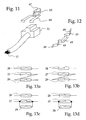
- Fig. 11
- eine perspektivische Skizze eines Sensors und eine Federelements zum Befestigen des Sensors in einer T-förmig hinterschnittenen Nut.
- Fig. 12
- eine Aufsicht auf eine andere Ausführungsform eines solchen Federelements.
- Fig. 13
- vier Schaltschemen, die eine Erfassung des Sensorzustands mit zwei elektrischen Leitungen ermöglichen.
- Das in Figur 1 dargestellte Kernstück des Sensors 11 ist aus einer Printplatte 13 und zwei ersten Reedkontakten 15,16 und einem dritten Reedkontakt 17 zusammengesetzt. Die ersten beiden Reedkontakte 15 und 16 sind parallel angeordnete Schliesser. Der dritte Reedkontakt 17 ist in Serie mit dem ersten Reedkontakt 15 geschaltet und ein Öffner.
- Die ersten beiden Reedkontakt sind unterhalb der Printplatte 13 in einer gemeinsamen Ebene und so nebeneinander angeordnet, dass die Anschlusspunkte für die Reedkontakte in einem Rechteck angeordnet sind. Der dritte Reedkontakt 17 ist oberhalb der Printplatte 13 und parallel zu diesen angeordnet. Seine Anschlusspunkte liegen auf zwei Seiten des Rechtecks gebildet durch die Anschlusspunkte der ersten beiden Reedkontakte 15, 16.
- In der Ebene der beiden ersten Reedkontakte 15 und 16 ist ein Metallstab als magnetische Schirmung 19 angeordnet. Die räumliche Ausbildung dieser Schirmung ist von untergeordneter Bedeutung. Die Längsrichtung des Metallstabs ist im Beispiel senkrecht zur Längsrichtung der Reedkontakte 15 und 16 ausgerichtet. Die Breite des Metallstabs ist in Längsrichtung der Reedkontakte 15 und 16 gerichtet. Dadurch ist die Schirmung möglichst im Abstand zum dritten Reedkontakt angeordnet und schirmt die beiden ersten Reedkontakte gut ab.
- Diese erwähnten Teile sind in den in Figur 2 dargestellten Kunststoff-Sensorkörper 21 eingegossen. Dieser Sensorkörper 21 hat einen T-förmigen Querschnitt. Innerhalb des nach oben gerichteten Stammes des T ist der dritte Reedkontakt 17, im Balken des T sind die Printplatte und die beiden ersten Reedkontakte 15 und 16, sowie, falls vorhanden, die Schirmung 19 angeordnet. Der Sensorkörper 21 ist in seiner Form auf die Aufnahmeeinrichtung angepasst, die den Sensor aufnehmen soll. Die dargestellte zylindrische Form mit dem T-förmigen Querschnitt ist geeignet, den Sensor längsverschieblich in einer T-förmig hinterschnitten ausgebildeten Nut anzuordnen.
- Der in Figur 3 dargestellte Sensor 11 mit zwei des in Figur 4 dargestellten Rastkopfes 23 auf den beiden Befestigungsschwänzen 25 ist in unterschiedlichen Positionen in einer solchen T-förmig hinterschnittenen Nut festlegbar. Der Sensor 11 besitzt am zentralen Sensorkörper 21 auf den einander gegenüberliegenden, T-förmigen Stirnseiten, die senkrecht zur Längsrichtung der Reedkontakte liegen, je einen Befestigungsschwanz 25. Diese sind einstückig mit dem Sensorkörper 21 gegossen. Aus einer dieser Stirnseiten treten Anschlusskabel 27 für den Sensor heraus. Diese können entgegen der Darstellung auch auf beiden Stirnseiten austreten. Die Anschlusskabel 27 können durch Öffnungen 29 im Rastkopf 23 hindurch geführt werden.
- Am Rastkopf 23 ist eine Rastöffnung 31 zur Durchführung des Befestigungsschwanzes 25 ausgebildet. In dieser Rastöffnung 31 ist eine Rastlippe 33 ausgebildet, die mit den Zähnen 35 an den Befestigungsschwänzen 25 ein Eingriff gehen kann. Am Rastkopf ist eine Anschlagfläche 37 ausgebildet, die mit einer Stirnseite der die Nut bildenden Wandung zusammenwirken kann.
- In Figur 5 ist ein solcher Sensor 11 in einer Nut 41 in der Wandung eines Zylinders 43 angeordnet. Der Kolben 45 ist in einem Zylinderraum 47 linear beweglich gelagert. Er kann durch Luft, Hydrauliköl oder ein anderes Medium hin und her geschoben werden, oder aber er bewegt dieses Medium durch sein z.B. motorisch erwirkte Lageänderung. Für den Eintritt und den Austritt des Mediums sind in der Kolbenwandung Öffnungen 46 vorgesehen. Diese Bewegung des Kolbens wird mit Stempel 48 von einem Motor auf den Kolben oder vom Kolben auf beispielsweise ein Werkzeug übertragen. Am Umfang des Kolbens 45 ist ein ringförmiger Magnet 49 angeordnet. Eine Feldlinie 51 stellt das lokale Magnetfeld des Magneten 49 schematisch vereinfacht dar.
- In Figur 5 ist der Kolben im unsicheren Bereich B. In Figur 7 ist der Kolben 45 im sicheren Bereich A dargestellt. Wenn der Kolben 45 im unsicheren Bereich B vorliegt, ist der Magnetfeld des Magneten 49 nicht genügend stark, um die Reedkontakte im Sensor 11 zu schalten. Erst in einer Position, in welcher die Feldlinien sich durch die Reedkontakte hindurch erstrecken, vermag der Magnet diese zu schalten. Die beiden ersten Reedkontakte 15 und 16 sind dem Magneten näher. Sie schirmen daher den äusseren dritten Reedkontakt zusätzlich ab. Die Magnetlinien erstrecken sich, sobald diese in den Bereich der Kontaktelemente des Reedschalters gelangen, konzentriert durch diese hindurch und erregen dadurch in diesen die den Kontakt schliessende Kraft.
- In Figur 8 sind die selben Situationen wie in Figuren 5 und 7 dargestellt. Es ist der Sensor 11 aber mit zwei Schirmungen 19 versehen. Die Feldlinien 51 sind daher in beiden Stellungen des Kolbens 45 verzerrt. Es gibt daher in Bereich des Sensors 11 eine sichere Stellung A. Ausserhalb dieses Bereichs befindet sich der Kolben 45 in einer unsicheren Stellung. Der Übergangsbereich zwischen diesen Bereichen ist mit der Schirmung 19 präziser als ohne diese Schirmung.
- Weiter ist in Figur 8 im Unterschied zu den Figuren 1 bis 7 der Sensor 11 nicht mit zwei Befestigungsschwänzen 25, sondern mit zwei Einrastmechaniken, insbesondere zwei Einrastlippen 33, zum rastenden Eingreifen in die Zahnung 35 von Fixierungsteilen 53 ausgebildet. Diese Fixierungsteile 53 besitzen einen Befestigungsschwanz 25 mit einer Zahnung 35 und einen Anschlagkopf 55. Die Zähne des Befestigungsschwanzes 25 greifen in die Einrastlippen an Sensorkörper 21 ein. Da die in Eingriff mit diesen stehenden Befestigungsschwänze nicht mehr zurück gezogen werden können, ist dadurch der Sensorkörper in seiner Lage fixiert, sobald die beiden Anschlagköpfe der Fixierungsteile 53 in Anschlag mit dem Zylinder 43 sind. Damit die Anschlagköpfe nicht über die Länge des Zylinders 43 vorstehen, ist die Nut an ihrem Ende erweitert und die Anschlagköpfe 55 passen in die erweiterte Nut. Zweckmässigerweise sind die beiden seitlichen Flansche 59 der Nutwandung, die den Hinterschnitt bilden, an ihrem Ende ausgeschnitten.
- Die Eingriffnahme kann mit einem Werkzeug lösbar sein. Dazu ist entweder die Rastlippe 33 vom Befestigungsschwanz 25 weg drückbar, oder der Befestigungsschwanz 25 von der Einrastlippe 33 abhebbar. Im ersten Fall ist die Einrastlippe 33 federnd mit dem Sensorkörper 21 verbunden oder auf einem federnd mit dem Sensorkörper 21 verbundenen Teil ausgebildet. Im zweiten Fall sind die Befestigungsschwänze 25 federn gegenüber der Nut 41 abgestützt. Jedenfalls wird die Eingriffnahme durch Federmittel aufrechterhalten.
- Ein weiteres Beispiel für die sichere Befestigung des Sensors 11 in der Nut 41 eines Zylinders 43 ist in Figuren 9 und 10 dargestellt. Am Sensor 11 ist eine Befestigungsscheibe 61 befestigt, die aus einem härteren Material besteht als der Mantel des Zylinders, in welchem die T-förmig hinterschnittene Nut 41 ausgebildet ist. Diese Scheibe 61 ist mit einem Gewinde versehen, in welches eine Schraube 65 eingeschraubt ist. Am Rand oder an den vier Ecken der Scheibe 61 sind Zähne 63 ausgebildet. Diese Zähne können durch Anziehen der Schraube 65 in das Material der den Hinterschnitt der Nut 41 bildenden Flansche 59 eingedrückt werden. Die Zähne sind damit in Eingriff mit dem Flansch 59. Es hat sich so ein Formschluss gebildet. Diese Scheibe wird durch eine Feder 67 in dieser Eingriff nehmenden Stellung gehalten. Die Feder 67 kann, wie dargestellt, eine Schraubenfeder sein, oder aber auch eine Blattfeder. Die Federung kann vorgesehen sein zwischen dem Sensor mit Befestigungsscheibe und der Nut, oder aber zwischen dem Sensorkörper 21 und der Befestigungsscheibe 61. Durch zurückdrehen der Schraube 65 und Einpressen der Schraube entgegen der Federkraft der Feder 67 kann die Scheibe 61 aus der Eingriffnahme mit der Nutwandung gelöst werden, so dass der Sensor verschoben werden kann. Der Sensor wird sich aber nicht unbeabsichtigt verschieben, da die Eingriffnahme durch die Federkraft gesichert ist.
- Anstelle der Scheibe 61 kann auch eine Blattfeder mit Zähnen 63 und einem Gewinde versehen sein und daher die Aufgabe der Scheibe und der Feder gleichzeitig übernehmen. Zum Einpressen der Zähne in die Nutwandung kann auch ein vom Sensor unabhängiges Werkzeug verwendet werden anstelle der Schraube 65.
- Das in Figur 11 dargestellte Federelement zur Befestigung des Sensors 11 in einer T-förmig hinterschnittenen Nut 41 ist einstückig hergestellt aus einem Federstahl. Es besitzt einen den Sensorkörper 21 umfangenden Teil und einen Federteil mit zwei Zähnen 63, die in Eingriff mit einer Vertiefung in der Seitenwand der Nut, insbesondere des schmaleren und äusseren Teiles der T-förmigen Nut, gebracht werden können. Diese Vertiefungen können durch Eindrücken des Zahns 63 in das Aluminium des Kolbenmantels erreicht werden.
- Die den Sensorkörper 21 umfassenden Teile liegen in montierter Stellung zwischen dem Sensorkörper und dem Flansch 59. Sie können zusätzlich eine Federkraft auf den Sensor ausüben, die diesen gegen den Grund der Nut drückt. Die Zähne 63 im federnden Teil werden durch die Federkraft dieses Teil nach aussen gedrückt. Sie liegen in entspanntem Zustand des Federelements in grösserem Abstand voneinander als die Breite der Nut. Dadurch müssen sie beim Einführen des Federelements in die Nut unter Verformung der Federteile gegeneinander angenähert werden. Mit einem Schraubenzieher oder einem besonderen Werkzeug können die aus dem Federstahl herausgestanzten und umgeklappten Zähne 63 einander direkt gegenüber in das Aluminium des Flansches 59 eingepresst werden und halten dort daher formschlüssig.
- Eine Variante eines solchen Federelements ist in Figur 12 dargestellt. Diese besitzt ebenfalls Flansche 69, einen den Sensorkörper umfangenden Teil und zwei Federteile mit Zähnen 63. Diese liegen hier jedoch vor und hinter dem Sensor.
- In Figur 13 sind vier Schaltschemen dargestellt, bei denen die drei Reedkontakte 15,16,17 zu zwei Leiterbahnen zusammengefasst sind und drei unterscheidbare Schaltmuster aufweisen können. Abgesehen von diesen Schaltschemen ist es auch möglich, die drei Reedkontakte einzeln abzugreifen und mit einer nachgeschalteten Logik den Schaltzustand des Sensors zu analysieren.
- In Figuren 13a und 13b sind jeweils der erste Reedkontakt 15 und der dritte Reedkontakt 17 in Serie geschaltet. Bei der Serieschaltung ist es erforderlich, dass der erste Reedkontakt ein Schliesser und der dritte ein Öffner ist, um ein eindeutiges Sensorsignal zu erhalten. Der zweite Reedkontakt kann ein Öffner (Fig. 13b) oder ein Schliesser (Fig. 13a) sein.
- In den Figuren 13c und 13d sind der erste Reedkontakt 15 und dritte Reedkontakt 17 parallel geschaltet. Dies erfordert, dass der erste Reedkontakt 15 ein Öffner ist und der dritte Reedkontakt 17 ein Schliesser ist, damit eindeutige Sensorsignale generiert werden. Der zweite Reedkontakt kann dabei wieder ein Öffner oder ein Schliesser sein.
- Der Zustand der Reedkontakte wird mit einer logischen Schaltung (vorzugsweise mit einem Elektronikbauteil) analysiert. Bei den angeführten Schaltungen gilt folgendes:
Schema 13a 13b 13c 13d Reedkontakte 15/17 16 15/17 16 15/17 16 15/17 16 Aktiviert durch Erregerteil 1 1 1 0 0 1 0 0 Nicht aktiviert 0 0 0 1 1 0 1 1 Aktiviert durch Fremdmagnetfeld 0 1 0 0 1 1 1 0 - Sind die Reedkontakte einzeln abgegriffen, kann jeder Reedkontakt unabhängig vom andern ein Öffner oder ein Schliesser sein. Die logische Schaltung muss entsprechend so ausgelegt sein, dass die Offenstellung und Geschlossenstellung der einzelnen Reedkontakte richtig interpretiert werden.
Claims (18)
wobei der Befestigungsschwanz (25) mit einer Zahnung (35) und der Rastkopf (23) mit einer in der Zahnung (35) einrastendenden Rastmechanik (33) versehen ist, die zusammenwirkend das Aufstecken der beiden Rastköpfe (23) auf je einen Befestigungsschwanz (25) erlauben, jedoch das Abziehen des aufgesteckten Rastkopfes (23) verhindern.
wobei der Befestigungsschwanz (25) mit einer Zahnung (35) versehen ist, die mit einer der Rastmechaniken (33) am Sensor (11) zusammenwirkend das Aufstecken der beiden Fixierungsteile (53) auf den Sensor (11) erlauben, jedoch das Abziehen des aufgesteckten Fixierungsteiles (53) verhindern.
Applications Claiming Priority (1)
| Application Number | Priority Date | Filing Date | Title |
|---|---|---|---|
| CH8822006 | 2006-06-01 |
Publications (3)
| Publication Number | Publication Date |
|---|---|
| EP1862767A2 true EP1862767A2 (de) | 2007-12-05 |
| EP1862767A3 EP1862767A3 (de) | 2013-12-04 |
| EP1862767B1 EP1862767B1 (de) | 2015-05-27 |
Family
ID=38562927
Family Applications (1)
| Application Number | Title | Priority Date | Filing Date |
|---|---|---|---|
| EP07405110.3A Active EP1862767B1 (de) | 2006-06-01 | 2007-04-11 | Sicherheits-Positionssensor für Zylinder, Zylinder mit einem solchen Positionssensor |
Country Status (4)
| Country | Link |
|---|---|
| US (2) | US7852067B2 (de) |
| EP (1) | EP1862767B1 (de) |
| JP (1) | JP5171110B2 (de) |
| CN (1) | CN101082478B (de) |
Cited By (2)
| Publication number | Priority date | Publication date | Assignee | Title |
|---|---|---|---|---|
| DE102016205069A1 (de) | 2016-03-29 | 2017-10-05 | Contitech Luftfedersysteme Gmbh | Positionsbestimmungseinrichtung für Kolben-Zylinder-Anordnungen |
| EP4197704A1 (de) | 2021-12-17 | 2023-06-21 | Göpel electronic GmbH | Positionsdetektor |
Families Citing this family (11)
| Publication number | Priority date | Publication date | Assignee | Title |
|---|---|---|---|---|
| CH702223B1 (de) * | 2006-06-01 | 2011-05-31 | Elesta Relays Gmbh | Set mit einem Positionssensor und einem Erregerteil. |
| WO2009073170A2 (en) | 2007-12-03 | 2009-06-11 | Cts Corporation | Linear position sensor |
| DE112009003688B4 (de) | 2008-11-26 | 2013-09-19 | Cts Corporation | Linearpositionssensor mit Drehblockiervorrichtung |
| US8664947B2 (en) | 2008-12-02 | 2014-03-04 | Cts Corporation | Actuator and sensor assembly |
| US9435630B2 (en) | 2010-12-08 | 2016-09-06 | Cts Corporation | Actuator and linear position sensor assembly |
| CN102254643B (zh) * | 2011-05-17 | 2013-08-14 | 芜湖飞云电工机械有限公司 | 一种电缆钢包机钢带锁紧装置 |
| CN102680217B (zh) * | 2012-04-20 | 2015-02-18 | 杰锋汽车动力系统股份有限公司 | 一种单向阀开启压力检测装置 |
| CN109922646B (zh) * | 2019-03-18 | 2020-10-16 | 南京工业职业技术学院 | 屏蔽簧片 |
| JP7120264B2 (ja) * | 2020-02-14 | 2022-08-17 | Tdk株式会社 | 位置検出装置、レンズモジュールおよび撮像装置 |
| WO2021195232A1 (en) * | 2020-03-24 | 2021-09-30 | Stabilus Gmbh | Piston assemblies and methods of using same |
| CN111403193A (zh) * | 2020-04-16 | 2020-07-10 | 鞍山电磁阀有限责任公司 | 行程开关 |
Family Cites Families (20)
| Publication number | Priority date | Publication date | Assignee | Title |
|---|---|---|---|---|
| US2877361A (en) * | 1957-04-12 | 1959-03-10 | Holmes Electric Protective Com | Burglar alarm system |
| JPS5441143B2 (de) * | 1974-02-04 | 1979-12-06 | ||
| DE7635587U1 (de) * | 1976-11-11 | 1977-03-10 | Festo-Maschinenfabrik Gottlieb Stoll, 7300 Esslingen | Pneumatische oder hydraulische Kolbenzylinder-Einheit |
| JPS54158991U (de) * | 1978-04-28 | 1979-11-06 | ||
| DE3240351A1 (de) * | 1982-10-30 | 1984-05-03 | Wabco Westinghouse Steuerungstechnik GmbH & Co, 3000 Hannover | Druckmittelbetaetigter arbeitszylinder |
| DE3410858A1 (de) * | 1984-03-23 | 1985-10-03 | Alfred Teves Gmbh, 6000 Frankfurt | Elektrischer schalter |
| US4967792A (en) * | 1984-07-18 | 1990-11-06 | Magee Anthony J | Sensing the open and/or closed condition of valves |
| JPS63122902A (ja) * | 1986-11-13 | 1988-05-26 | Ckd Controls Ltd | 移動体の位置確認装置 |
| US4755636A (en) * | 1987-06-24 | 1988-07-05 | Taiyo, Ltd. | Piston position detecting device for fluid pressure cylinder |
| JP2529329B2 (ja) * | 1988-01-18 | 1996-08-28 | シーケーディ 株式会社 | 磁気近接センサ |
| DE8901770U1 (de) * | 1989-02-15 | 1990-07-26 | Schaltbau GmbH, 8000 München | Stellantrieb |
| DE9115266U1 (de) * | 1991-12-09 | 1992-02-06 | alfasystem GmbH Herstellung und Vertrieb von elektronischen Sicherheitssystemen, 82110 Germering | Öffnungsmelder |
| JP2601918Y2 (ja) * | 1993-09-07 | 1999-12-13 | 株式会社コガネイ | 流体圧シリンダの位置検出装置 |
| JP2857332B2 (ja) * | 1994-10-17 | 1999-02-17 | シーケーディ株式会社 | ピストン位置検出装置 |
| DE19717804A1 (de) * | 1997-04-26 | 1998-11-05 | Michael Schich | Go-Kart-Schaltgetriebe |
| JP4029506B2 (ja) * | 1999-01-25 | 2008-01-09 | 松下電器産業株式会社 | ガス遮断装置 |
| JP4235979B2 (ja) * | 1999-07-01 | 2009-03-11 | 綜合警備保障株式会社 | マグネットスイッチ |
| JP2002211626A (ja) * | 2001-01-12 | 2002-07-31 | Toska Co Ltd | 巻装バンド |
| US6642704B2 (en) * | 2001-09-28 | 2003-11-04 | Eaton Corporation | Device for sensing electrical current and housing therefor |
| JP4093477B2 (ja) * | 2003-09-08 | 2008-06-04 | 株式会社近畿システムプラン | インシュロック |
-
2007
- 2007-04-11 EP EP07405110.3A patent/EP1862767B1/de active Active
- 2007-05-28 JP JP2007140199A patent/JP5171110B2/ja not_active Expired - Fee Related
- 2007-05-31 US US11/806,414 patent/US7852067B2/en not_active Expired - Fee Related
- 2007-06-01 CN CN2007101064759A patent/CN101082478B/zh not_active Expired - Fee Related
-
2010
- 2010-11-12 US US12/944,829 patent/US20110062949A1/en not_active Abandoned
Cited By (4)
| Publication number | Priority date | Publication date | Assignee | Title |
|---|---|---|---|---|
| DE102016205069A1 (de) | 2016-03-29 | 2017-10-05 | Contitech Luftfedersysteme Gmbh | Positionsbestimmungseinrichtung für Kolben-Zylinder-Anordnungen |
| EP4197704A1 (de) | 2021-12-17 | 2023-06-21 | Göpel electronic GmbH | Positionsdetektor |
| DE102021133643A1 (de) | 2021-12-17 | 2023-06-22 | Göpel electronic GmbH | Positionsdetektor |
| DE102021133643B4 (de) | 2021-12-17 | 2024-01-25 | Göpel electronic GmbH | Positionsdetektor |
Also Published As
| Publication number | Publication date |
|---|---|
| CN101082478B (zh) | 2010-12-08 |
| EP1862767B1 (de) | 2015-05-27 |
| CN101082478A (zh) | 2007-12-05 |
| EP1862767A3 (de) | 2013-12-04 |
| US7852067B2 (en) | 2010-12-14 |
| US20070279048A1 (en) | 2007-12-06 |
| US20110062949A1 (en) | 2011-03-17 |
| JP5171110B2 (ja) | 2013-03-27 |
| JP2007324129A (ja) | 2007-12-13 |
Similar Documents
| Publication | Publication Date | Title |
|---|---|---|
| EP1862767B1 (de) | Sicherheits-Positionssensor für Zylinder, Zylinder mit einem solchen Positionssensor | |
| EP3220781B1 (de) | Verschlussvorrichtung zum befestigen eines elektronischen geräts an einer halteeinrichtung | |
| EP3362801B1 (de) | Sensorbaugruppe für einen stromsensor, sowie verfahren zur montage einer sensorbaugruppe | |
| EP0747603A1 (de) | Plattenverbinder | |
| EP0937311A1 (de) | Vorrichtung zur befestigung eines entfernungssensors an einem kraftfahrzeug | |
| EP1249681B1 (de) | Magnetostriktive Wegmessvorrichtung | |
| DE602004013416T2 (de) | Linearstellelement | |
| DE102009015486A1 (de) | Elektromagnetischer Aktuator | |
| DE3628211A1 (de) | Komponentenhalterung | |
| DE202007007564U1 (de) | Kodiersystem bei D-Subminiatur-Steckverbindern | |
| EP0292743B1 (de) | Türschliesser mit einer Schliesskraft-Anzeigevorrichtung | |
| DE102007062099B4 (de) | Positionserfassungseinrichtung | |
| DE102012006264A1 (de) | In einer T-Nut befestigbarer Zylinderschalter, der aus dem Klemmzustand lösbar ist | |
| DE102013216881A1 (de) | Linearantrieb | |
| EP0207270A2 (de) | Berührungslos arbeitende Näherungsschalteinrichtung | |
| EP3152070B1 (de) | Anhängekupplung | |
| WO2010037442A1 (de) | Schalter | |
| DE102014102793A1 (de) | Befestigungselement für einen Stromsensor | |
| DE102019106365A1 (de) | Elektromagnetische Stellanordnung | |
| EP0943824A1 (de) | Mechanisches Verbindungselement | |
| DE102007020313B4 (de) | Vorrichtung zum Überwachen des Zustandes einer Schutzeinrichtung einer Maschine | |
| WO2010006762A1 (de) | Wippschalter | |
| DE3422222A1 (de) | Gestell aus einem profilstab und daran mit einem verbinder angebrachter platte o. dgl. gestellteil | |
| DE3209550C2 (de) | Gehäuse für elektrotechnische Geräte | |
| DE69305423T2 (de) | Verkehrszeichen |
Legal Events
| Date | Code | Title | Description |
|---|---|---|---|
| PUAI | Public reference made under article 153(3) epc to a published international application that has entered the european phase |
Free format text: ORIGINAL CODE: 0009012 |
|
| AK | Designated contracting states |
Kind code of ref document: A2 Designated state(s): AT BE BG CH CY CZ DE DK EE ES FI FR GB GR HU IE IS IT LI LT LU LV MC MT NL PL PT RO SE SI SK TR |
|
| AX | Request for extension of the european patent |
Extension state: AL BA HR MK YU |
|
| RAP1 | Party data changed (applicant data changed or rights of an application transferred) |
Owner name: PILZ AUSLANDSBETEILIGUNGEN GMBH |
|
| RIC1 | Information provided on ipc code assigned before grant |
Ipc: G01D 5/251 20060101ALI20130709BHEP Ipc: G01D 5/06 20060101AFI20130709BHEP |
|
| PUAL | Search report despatched |
Free format text: ORIGINAL CODE: 0009013 |
|
| AK | Designated contracting states |
Kind code of ref document: A3 Designated state(s): AT BE BG CH CY CZ DE DK EE ES FI FR GB GR HU IE IS IT LI LT LU LV MC MT NL PL PT RO SE SI SK TR |
|
| AX | Request for extension of the european patent |
Extension state: AL BA HR MK RS |
|
| RIC1 | Information provided on ipc code assigned before grant |
Ipc: G01D 5/06 20060101AFI20131028BHEP Ipc: G01D 5/251 20060101ALI20131028BHEP |
|
| 17P | Request for examination filed |
Effective date: 20140521 |
|
| RBV | Designated contracting states (corrected) |
Designated state(s): AT BE BG CH CY CZ DE DK EE ES FI FR GB GR HU IE IS IT LI LT LU LV MC MT NL PL PT RO SE SI SK TR |
|
| RBV | Designated contracting states (corrected) |
Designated state(s): AT BE BG CH CY CZ DE DK EE ES FI FR GB GR HU IE IS IT LI LT LU LV MC MT NL PL PT RO SE SI SK TR |
|
| AKX | Designation fees paid |
Designated state(s): AT BE BG CH CY CZ DE DK EE ES FI FR GB GR HU IE IS IT LI LT LU LV MC MT NL PL PT RO SE SI SK TR |
|
| GRAP | Despatch of communication of intention to grant a patent |
Free format text: ORIGINAL CODE: EPIDOSNIGR1 |
|
| INTG | Intention to grant announced |
Effective date: 20141127 |
|
| RIN1 | Information on inventor provided before grant (corrected) |
Inventor name: SCHMID, MAX Inventor name: MAHDI, FOUAD |
|
| GRAS | Grant fee paid |
Free format text: ORIGINAL CODE: EPIDOSNIGR3 |
|
| GRAA | (expected) grant |
Free format text: ORIGINAL CODE: 0009210 |
|
| AK | Designated contracting states |
Kind code of ref document: B1 Designated state(s): AT BE BG CH CY CZ DE DK EE ES FI FR GB GR HU IE IS IT LI LT LU LV MC MT NL PL PT RO SE SI SK TR |
|
| REG | Reference to a national code |
Ref country code: GB Ref legal event code: FG4D Free format text: NOT ENGLISH |
|
| REG | Reference to a national code |
Ref country code: CH Ref legal event code: EP |
|
| REG | Reference to a national code |
Ref country code: AT Ref legal event code: REF Ref document number: 729102 Country of ref document: AT Kind code of ref document: T Effective date: 20150615 |
|
| REG | Reference to a national code |
Ref country code: IE Ref legal event code: FG4D Free format text: LANGUAGE OF EP DOCUMENT: GERMAN |
|
| REG | Reference to a national code |
Ref country code: CH Ref legal event code: NV Representative=s name: RIEDERER HASLER AND PARTNER PATENTANWAELTE AG, LI |
|
| REG | Reference to a national code |
Ref country code: DE Ref document number: 502007013946 Country of ref document: DE Effective date: 20150709 Ref legal event code: R096 |
|
| REG | Reference to a national code |
Ref country code: LT Ref legal event code: MG4D |
|
| PG25 | Lapsed in a contracting state [announced via postgrant information from national office to epo] |
Ref country code: FI Free format text: LAPSE BECAUSE OF FAILURE TO SUBMIT A TRANSLATION OF THE DESCRIPTION OR TO PAY THE FEE WITHIN THE PRESCRIBED TIME-LIMIT Effective date: 20150527 Ref country code: PT Free format text: LAPSE BECAUSE OF FAILURE TO SUBMIT A TRANSLATION OF THE DESCRIPTION OR TO PAY THE FEE WITHIN THE PRESCRIBED TIME-LIMIT Effective date: 20150928 Ref country code: ES Free format text: LAPSE BECAUSE OF FAILURE TO SUBMIT A TRANSLATION OF THE DESCRIPTION OR TO PAY THE FEE WITHIN THE PRESCRIBED TIME-LIMIT Effective date: 20150527 Ref country code: LT Free format text: LAPSE BECAUSE OF FAILURE TO SUBMIT A TRANSLATION OF THE DESCRIPTION OR TO PAY THE FEE WITHIN THE PRESCRIBED TIME-LIMIT Effective date: 20150527 |
|
| REG | Reference to a national code |
Ref country code: NL Ref legal event code: MP Effective date: 20150527 |
|
| PG25 | Lapsed in a contracting state [announced via postgrant information from national office to epo] |
Ref country code: LV Free format text: LAPSE BECAUSE OF FAILURE TO SUBMIT A TRANSLATION OF THE DESCRIPTION OR TO PAY THE FEE WITHIN THE PRESCRIBED TIME-LIMIT Effective date: 20150527 Ref country code: IS Free format text: LAPSE BECAUSE OF FAILURE TO SUBMIT A TRANSLATION OF THE DESCRIPTION OR TO PAY THE FEE WITHIN THE PRESCRIBED TIME-LIMIT Effective date: 20150927 Ref country code: GR Free format text: LAPSE BECAUSE OF FAILURE TO SUBMIT A TRANSLATION OF THE DESCRIPTION OR TO PAY THE FEE WITHIN THE PRESCRIBED TIME-LIMIT Effective date: 20150828 Ref country code: BG Free format text: LAPSE BECAUSE OF FAILURE TO SUBMIT A TRANSLATION OF THE DESCRIPTION OR TO PAY THE FEE WITHIN THE PRESCRIBED TIME-LIMIT Effective date: 20150827 |
|
| PG25 | Lapsed in a contracting state [announced via postgrant information from national office to epo] |
Ref country code: DK Free format text: LAPSE BECAUSE OF FAILURE TO SUBMIT A TRANSLATION OF THE DESCRIPTION OR TO PAY THE FEE WITHIN THE PRESCRIBED TIME-LIMIT Effective date: 20150527 Ref country code: EE Free format text: LAPSE BECAUSE OF FAILURE TO SUBMIT A TRANSLATION OF THE DESCRIPTION OR TO PAY THE FEE WITHIN THE PRESCRIBED TIME-LIMIT Effective date: 20150527 |
|
| PG25 | Lapsed in a contracting state [announced via postgrant information from national office to epo] |
Ref country code: RO Free format text: LAPSE BECAUSE OF NON-PAYMENT OF DUE FEES Effective date: 20150527 Ref country code: PL Free format text: LAPSE BECAUSE OF FAILURE TO SUBMIT A TRANSLATION OF THE DESCRIPTION OR TO PAY THE FEE WITHIN THE PRESCRIBED TIME-LIMIT Effective date: 20150527 Ref country code: CZ Free format text: LAPSE BECAUSE OF FAILURE TO SUBMIT A TRANSLATION OF THE DESCRIPTION OR TO PAY THE FEE WITHIN THE PRESCRIBED TIME-LIMIT Effective date: 20150527 Ref country code: SK Free format text: LAPSE BECAUSE OF FAILURE TO SUBMIT A TRANSLATION OF THE DESCRIPTION OR TO PAY THE FEE WITHIN THE PRESCRIBED TIME-LIMIT Effective date: 20150527 |
|
| REG | Reference to a national code |
Ref country code: DE Ref legal event code: R097 Ref document number: 502007013946 Country of ref document: DE |
|
| PLBE | No opposition filed within time limit |
Free format text: ORIGINAL CODE: 0009261 |
|
| STAA | Information on the status of an ep patent application or granted ep patent |
Free format text: STATUS: NO OPPOSITION FILED WITHIN TIME LIMIT |
|
| REG | Reference to a national code |
Ref country code: FR Ref legal event code: PLFP Year of fee payment: 10 |
|
| 26N | No opposition filed |
Effective date: 20160301 |
|
| PG25 | Lapsed in a contracting state [announced via postgrant information from national office to epo] |
Ref country code: SI Free format text: LAPSE BECAUSE OF FAILURE TO SUBMIT A TRANSLATION OF THE DESCRIPTION OR TO PAY THE FEE WITHIN THE PRESCRIBED TIME-LIMIT Effective date: 20150527 |
|
| PG25 | Lapsed in a contracting state [announced via postgrant information from national office to epo] |
Ref country code: BE Free format text: LAPSE BECAUSE OF NON-PAYMENT OF DUE FEES Effective date: 20160430 |
|
| GBPC | Gb: european patent ceased through non-payment of renewal fee |
Effective date: 20160411 |
|
| PG25 | Lapsed in a contracting state [announced via postgrant information from national office to epo] |
Ref country code: LU Free format text: LAPSE BECAUSE OF FAILURE TO SUBMIT A TRANSLATION OF THE DESCRIPTION OR TO PAY THE FEE WITHIN THE PRESCRIBED TIME-LIMIT Effective date: 20160411 |
|
| REG | Reference to a national code |
Ref country code: IE Ref legal event code: MM4A |
|
| PG25 | Lapsed in a contracting state [announced via postgrant information from national office to epo] |
Ref country code: GB Free format text: LAPSE BECAUSE OF NON-PAYMENT OF DUE FEES Effective date: 20160411 |
|
| REG | Reference to a national code |
Ref country code: FR Ref legal event code: PLFP Year of fee payment: 11 |
|
| PG25 | Lapsed in a contracting state [announced via postgrant information from national office to epo] |
Ref country code: IE Free format text: LAPSE BECAUSE OF NON-PAYMENT OF DUE FEES Effective date: 20160411 |
|
| REG | Reference to a national code |
Ref country code: AT Ref legal event code: MM01 Ref document number: 729102 Country of ref document: AT Kind code of ref document: T Effective date: 20160411 |
|
| PG25 | Lapsed in a contracting state [announced via postgrant information from national office to epo] |
Ref country code: NL Free format text: LAPSE BECAUSE OF FAILURE TO SUBMIT A TRANSLATION OF THE DESCRIPTION OR TO PAY THE FEE WITHIN THE PRESCRIBED TIME-LIMIT Effective date: 20150527 Ref country code: SE Free format text: LAPSE BECAUSE OF FAILURE TO SUBMIT A TRANSLATION OF THE DESCRIPTION OR TO PAY THE FEE WITHIN THE PRESCRIBED TIME-LIMIT Effective date: 20150527 |
|
| PG25 | Lapsed in a contracting state [announced via postgrant information from national office to epo] |
Ref country code: AT Free format text: LAPSE BECAUSE OF NON-PAYMENT OF DUE FEES Effective date: 20160411 |
|
| REG | Reference to a national code |
Ref country code: FR Ref legal event code: PLFP Year of fee payment: 12 |
|
| PG25 | Lapsed in a contracting state [announced via postgrant information from national office to epo] |
Ref country code: CY Free format text: LAPSE BECAUSE OF FAILURE TO SUBMIT A TRANSLATION OF THE DESCRIPTION OR TO PAY THE FEE WITHIN THE PRESCRIBED TIME-LIMIT Effective date: 20150527 Ref country code: HU Free format text: LAPSE BECAUSE OF FAILURE TO SUBMIT A TRANSLATION OF THE DESCRIPTION OR TO PAY THE FEE WITHIN THE PRESCRIBED TIME-LIMIT; INVALID AB INITIO Effective date: 20070411 |
|
| PG25 | Lapsed in a contracting state [announced via postgrant information from national office to epo] |
Ref country code: TR Free format text: LAPSE BECAUSE OF FAILURE TO SUBMIT A TRANSLATION OF THE DESCRIPTION OR TO PAY THE FEE WITHIN THE PRESCRIBED TIME-LIMIT Effective date: 20150527 Ref country code: MT Free format text: LAPSE BECAUSE OF FAILURE TO SUBMIT A TRANSLATION OF THE DESCRIPTION OR TO PAY THE FEE WITHIN THE PRESCRIBED TIME-LIMIT Effective date: 20150527 Ref country code: MC Free format text: LAPSE BECAUSE OF FAILURE TO SUBMIT A TRANSLATION OF THE DESCRIPTION OR TO PAY THE FEE WITHIN THE PRESCRIBED TIME-LIMIT Effective date: 20150527 |
|
| PGFP | Annual fee paid to national office [announced via postgrant information from national office to epo] |
Ref country code: DE Payment date: 20250422 Year of fee payment: 19 |
|
| PGFP | Annual fee paid to national office [announced via postgrant information from national office to epo] |
Ref country code: IT Payment date: 20250424 Year of fee payment: 19 |
|
| PGFP | Annual fee paid to national office [announced via postgrant information from national office to epo] |
Ref country code: FR Payment date: 20250423 Year of fee payment: 19 |
|
| PGFP | Annual fee paid to national office [announced via postgrant information from national office to epo] |
Ref country code: CH Payment date: 20250501 Year of fee payment: 19 |