EP1862767A2 - Capteur de position de sécurité pour cylindre, cylindre doté d'un tel capteur de position - Google Patents
Capteur de position de sécurité pour cylindre, cylindre doté d'un tel capteur de position Download PDFInfo
- Publication number
- EP1862767A2 EP1862767A2 EP07405110A EP07405110A EP1862767A2 EP 1862767 A2 EP1862767 A2 EP 1862767A2 EP 07405110 A EP07405110 A EP 07405110A EP 07405110 A EP07405110 A EP 07405110A EP 1862767 A2 EP1862767 A2 EP 1862767A2
- Authority
- EP
- European Patent Office
- Prior art keywords
- sensor
- cylinder
- piston
- reed
- magnet
- Prior art date
- Legal status (The legal status is an assumption and is not a legal conclusion. Google has not performed a legal analysis and makes no representation as to the accuracy of the status listed.)
- Granted
Links
Images


Classifications
-
- G—PHYSICS
- G01—MEASURING; TESTING
- G01D—MEASURING NOT SPECIALLY ADAPTED FOR A SPECIFIC VARIABLE; ARRANGEMENTS FOR MEASURING TWO OR MORE VARIABLES NOT COVERED IN A SINGLE OTHER SUBCLASS; TARIFF METERING APPARATUS; MEASURING OR TESTING NOT OTHERWISE PROVIDED FOR
- G01D5/00—Mechanical means for transferring the output of a sensing member; Means for converting the output of a sensing member to another variable where the form or nature of the sensing member does not constrain the means for converting; Transducers not specially adapted for a specific variable
- G01D5/02—Mechanical means for transferring the output of a sensing member; Means for converting the output of a sensing member to another variable where the form or nature of the sensing member does not constrain the means for converting; Transducers not specially adapted for a specific variable using mechanical means
- G01D5/06—Mechanical means for transferring the output of a sensing member; Means for converting the output of a sensing member to another variable where the form or nature of the sensing member does not constrain the means for converting; Transducers not specially adapted for a specific variable using mechanical means acting through a wall or enclosure, e.g. by bellows, by magnetic coupling
-
- G—PHYSICS
- G01—MEASURING; TESTING
- G01D—MEASURING NOT SPECIALLY ADAPTED FOR A SPECIFIC VARIABLE; ARRANGEMENTS FOR MEASURING TWO OR MORE VARIABLES NOT COVERED IN A SINGLE OTHER SUBCLASS; TARIFF METERING APPARATUS; MEASURING OR TESTING NOT OTHERWISE PROVIDED FOR
- G01D5/00—Mechanical means for transferring the output of a sensing member; Means for converting the output of a sensing member to another variable where the form or nature of the sensing member does not constrain the means for converting; Transducers not specially adapted for a specific variable
- G01D5/12—Mechanical means for transferring the output of a sensing member; Means for converting the output of a sensing member to another variable where the form or nature of the sensing member does not constrain the means for converting; Transducers not specially adapted for a specific variable using electric or magnetic means
- G01D5/25—Selecting one or more conductors or channels from a plurality of conductors or channels, e.g. by closing contacts
- G01D5/251—Selecting one or more conductors or channels from a plurality of conductors or channels, e.g. by closing contacts one conductor or channel
- G01D5/2515—Selecting one or more conductors or channels from a plurality of conductors or channels, e.g. by closing contacts one conductor or channel with magnetically controlled switches, e.g. by movement of a magnet
Definitions
- the invention relates to a sensor for monitoring a relative to the sensor translationally displaceable part with respect to its position on the displacement axis and a cylinder with such a sensor for monitoring the position of the piston with respect to its axis of movement.
- the invention relates to a safety position sensor for a pneumatic or a hydraulic cylinder and such a cylinder with the position sensor.
- Another object of the invention is the positioning of a sensor and the safe Fixing the sensor, for example, to achieve a cylinder in this position with technically simple means.
- a sensor for monitoring a relative to the sensor translationally displaceable part with respect to its position on the displacement axis is actuated by means of a displaceable part arranged with respect to north and south pole oriented in the direction of displacement magnet.
- it has three reed contacts arranged in parallel, of which a first and a second reed contact are arranged in one plane. They are arranged with their longitudinal axes parallel next to each other. By virtue of this arrangement, they can be actuated virtually simultaneously by the magnetic field of the magnet arranged on the displaceable part.
- the third reed contact is arranged at a distance from the plane of the first and second reed contact.
- Such a sensor, arranged with the third reed contact at a greater distance from the actuating magnet than the other two reed contacts, is safe from manipulation by external magnetic fields.
- An externally applied external magnetic field will always first actuate the third reed switch, which is closer to the externally applied magnet. It is practically impossible not to operate the arranged close to the first two reed contacts third reed contact when with an external magnetic field of the first and the second reed contact is actuated.
- Such a sensor is particularly suitable for detecting the position of a piston in a cylinder.
- the sensor is arranged on the cylinder, the made of non-magnetic material, such as aluminum, and the piston carries a magnet, preferably a magnetic ring around the piston.
- the third reed contact is expediently at most as sensitive as the two reed contacts that are arranged in parallel, so that it does not respond with a stronger magnetic field than this one. It is then the distance to the exciter magnet, the deciding factor.
- the sensor In order to make the range for a sensor signal more precise and to make the boundary between sensor signal exciting and no sensor signal exciting position of the magnet as short as possible, is at one end of the two same switching reed contacts, and preferably at both ends of the reed contacts, the sensor with a shield , in particular an iron part is equipped.
- This shield distorts the magnetic field of the exciter magnet, so that the magnetic field is deflected by the material of the shield from the area of the reed contacts.
- the magnetic field jumps with the one pole from the shield and with the other pole in the shielding, ie, if until then the field lines in the north were deformed by the shielding and the field lines in the south remained virtually undeformed, The deformation suddenly jumps over to the field lines of the South Pole, while the field lines of the North Pole remain largely undeformed. This achieves a clearer signal.
- the two-sided shield has the particular advantage that a direction reversed installation of the sensor is excluded. Alternatively, an unambiguous identification of the sensor and the position of the shielding can be provided.
- the senor is provided with a mounting tail at opposite ends.
- This mounting tail prevents each shift of the sensor from the tail end away, so that with two opposite mounting tails displacement in both directions is prevented.
- the fastening tail is provided with a toothing and the locking head with a latching in the toothing locking mechanism.
- the teeth and the locking mechanism cooperatively allow the attachment of the locking heads, but they prevent the removal of the once plugged locking head.
- Such serrations and locking mechanisms are known from cable ties ago.
- the latching mechanism can be released by means of a tool from the operative connection with the fastening tail.
- the simple and secure immovable positioning of a sensor for monitoring a relative to the sensor translationally displaceable part with respect to its position on the displacement axis, which is actuated by means of a displaceable part magnet is achieved according to the invention characterized in that the sensor is provided at opposite ends with a mounting tail is, and that two locking heads are provided.
- Each mounting tail is provided with a toothing and each locking head with a latching in the toothing locking mechanism, the cooperating the attachment of the locking heads allow the mounting tails, but prevent the removal of the once plugged locking head.
- the latching heads have a stop which, after assembly of the sensor, is e.g. to a cylinder, presses against an abutment surface of the cylinder so that the sensor is prevented by the one attachment tail from moving in one direction and is prevented from moving in the opposite direction with the other attachment tail.
- a stop of the locking heads can be connected via a thread with the locking mechanism of the locking heads, which thread extends in the longitudinal direction of the mounting tails.
- the stops must be permanently connected to the locking mechanism. A twisting of the stops around the thread axis must not lead to a release of the locking head from the fastening tail.
- the senor can be formed with two oppositely locking latching mechanisms, and the fixation of the sensor by inserting provided with stops and a toothing mounting tails. These are inserted from both sides into the two locking mechanisms.
- the attachment tails are designed such that they can be accommodated next to each other in a e.g. formed on the cylinder groove, and therefore can overlap each other in the longitudinal direction.
- the senor is characterized by a fastening device, which is designed to be cooperative or connected to the sensor. This prevents displacement of the sensor, in particular in the direction of displacement of the piston.
- the fastening device connects the sensor via a preferably releasable positive connection with a support for the sensor.
- a support for the sensor As a carrier, especially a wall of a cylinder is provided.
- the spring means are captive and hold the positive connection, e.g. between the fastening tail and the locking lip, or between a tooth and a recess pressed into the surface of the support, reliably upright.
- the sensor is preferably provided with a fastening device which has at least one tooth which can be pressed into the surface of a groove receiving the sensor. By this pressing a recess for the positive connection with the tooth can be achieved. Alternatively, however, it may also be e.g. a change in the surface of the carrier may be provided which has a series of recesses. In this case, the tooth engages in one of these recesses of R selectedung.
- the fastening device expediently comprises the sensor body. As a result, this is also positively connected to the fastening device.
- the fastening device can thus be a spring element released from the sensor.
- the fastening device can be produced in one piece from, for example, a spring steel strip which is designed to encompass the sensor body.
- at least two teeth are provided, which are brought into engagement with the surface of the groove in the carrier can.
- a flange 69 is also advantageously formed, which engages in the undercut of a T-shaped undercut groove.
- the invention also relates to a cylinder with a piston therein, wherein on the piston, a magnet is arranged, which is directed with the polarity in the direction of movement of the piston.
- a sensor for monitoring the position of the piston is arranged in the cylinder.
- the sensor is a sensor according to the invention.
- the sensor according to the invention ensures the monitoring of the piston position. It ensures safety by allowing two reed contacts to simultaneously respond to the magnetic field of the magnet and the third reed contact must not respond. The third reed contact is due to its greater distance from the magnet and piston in closer proximity to an externally acting external magnetic field.
- a groove in which the sensor is mounted displaceably in the direction of movement of the piston is advantageously formed a groove in which the sensor is mounted displaceably in the direction of movement of the piston.
- the sensor can be inserted from outside into this groove and brought into the desired position along the displacement direction possible therein.
- the sensor is advantageously designed as a cylindrical part (but not axially symmetric and therefore not circular cylindrical part, but preferably as a symmetrical to a mirror plane trained, rectangular parallelepiped) whose cylinder axis is parallel to the longitudinal direction of the reed contacts.
- a magnetic ring is formed around the piston so that the piston always exerts the same influence on the sensor independently of its rotational position about the piston axis.
- the core of the sensor 11 shown in Figure 1 is composed of a printed circuit board 13 and two first reed contacts 15,16 and a third reed contact 17.
- the first two reed contacts 15 and 16 are arranged in parallel closers.
- the third reed contact 17 is connected in series with the first reed contact 15 and an opener.
- the first two reed contact are below the printed circuit board 13 in a common plane and arranged side by side, that the connection points for the reed contacts are arranged in a rectangle.
- the third reed contact 17 is arranged above the printed circuit board 13 and parallel to it. Its connection points lie on two sides of the rectangle formed by the connection points of the first two reed contacts 15, 16.
- a metal rod is arranged as a magnetic shield 19.
- the spatial design of this shield is of minor importance.
- the longitudinal direction of the metal rod is aligned in the example perpendicular to the longitudinal direction of the reed contacts 15 and 16.
- the width of the metal rod is directed in the longitudinal direction of the reed contacts 15 and 16.
- This sensor body 21 has a T-shaped cross-section. Within the upwardly directed trunk of the T is the third reed contact 17, in the beam of the T, the printed circuit board and the two first reed contacts 15 and 16, and, if present, the shield 19 are arranged.
- the sensor body 21 is adapted in shape to the receiving device which is to receive the sensor.
- the illustrated cylindrical shape with the T-shaped cross-section is adapted to arrange the sensor longitudinally displaceable in a T-shaped undercut formed groove.
- the sensor 11 shown in Figure 3 with two of the locking head 23 shown in Figure 4 on the two mounting tails 25 is in different Positions in such a T-shaped undercut groove can be fixed.
- the sensor 11 has on the central sensor body 21 on the opposite, T-shaped end faces which are perpendicular to the longitudinal direction of the reed contacts, depending on a fastening tail 25. These are integrally molded with the sensor body 21. Connection cables 27 for the sensor exit from one of these end faces. These can, contrary to the illustration, also emerge on both end faces. The connection cables 27 can be guided through openings 29 in the latching head 23.
- a latching opening 31 is formed for the implementation of the fastening tail 25.
- a locking lip 33 is formed, which can go with the teeth 35 on the mounting tines 25 an engagement.
- a stop surface 37 is formed, which can cooperate with an end face of the groove forming wall.
- such a sensor 11 is arranged in a groove 41 in the wall of a cylinder 43.
- the piston 45 is mounted linearly movable in a cylinder chamber 47. It may be pushed back and forth by air, hydraulic oil or other medium, or it may move this medium by its e.g. motor-induced change of position.
- For the inlet and the outlet of the medium openings 46 are provided in the piston wall. This movement of the piston is transmitted with punch 48 from a motor to the piston or from the piston to, for example, a tool.
- an annular magnet 49 is arranged at the periphery of the piston 45.
- a field line 51 represents the local magnetic field of the magnet 49 schematically simplified.
- the piston is in the unsafe area B.
- the piston 45 is shown in the safe area A.
- the magnetic field of the magnet 49 is not strong enough to switch the reed contacts in the sensor 11. Only in a position in which the field lines extend through the reed contacts, the magnet is able to switch them.
- the first two reed contacts 15 and 16 are closer to the magnet. They therefore shield the outer third reed contact additionally.
- the magnetic lines extend as soon as they reach the area of the contact elements of the reed switch, concentrated through them and thereby excite in this the contact closing force.
- FIG. 8 shows the same situations as in FIGS. 5 and 7. It is the sensor 11 but provided with two shields 19. The field lines 51 are therefore distorted in both positions of the piston 45. There is therefore a safe position A in the region of the sensor 11. Outside this range, the piston 45 is in an unsafe position. The transition area between these areas is more accurate with the shield 19 than without this shielding.
- the sensor 11 is not formed with two mounting tails 25, but with two latching mechanisms, in particular two latching lips 33, for latching engagement in the teeth 35 of fixing members 53.
- These fixing parts 53 have a fastening tail 25 with a toothing 35 and an abutment head 55.
- the teeth of the fastening tail 25 engage in the latching lips on the sensor body 21. Since the standing in engagement with these mounting tails can not be pulled back, thereby the sensor body is fixed in position as soon as the two stop heads of the fixing members 53 are in abutment with the cylinder 43. So that the stop heads do not project beyond the length of the cylinder 43, the groove is widened at its end and the stopper heads 55 fit into the extended groove.
- the two lateral flanges 59 of the groove wall which form the undercut, cut at its end.
- the engagement can be solved with a tool.
- a tool For this purpose, either the locking lip 33 from the fastening tail 25 can be pressed away, or the fastening tail 25 of the latching lip 33 can be lifted.
- the latching lip 33 is resiliently connected to the sensor body 21 or formed on a resiliently connected to the sensor body 21 part.
- the mounting tails 25 are spring-supported relative to the groove 41. In any case, the intervention is maintained by spring means.
- FIG. 9 Another example of the secure attachment of the sensor 11 in the groove 41 of a cylinder 43 is shown in Figures 9 and 10.
- a fixing plate 61 is fixed, which consists of a harder material than the jacket of the cylinder, in which the T-shaped undercut groove 41 is formed.
- This disc 61 is provided with a thread into which a screw 65 is screwed.
- teeth 63 are formed. These teeth can by tightening the screw 65 in the material of the undercut of the groove 41 forming flanges 59th be pressed. The teeth are thus in engagement with the flange 59. It has formed such a positive connection.
- This disc is held by a spring 67 in this engagement taking position.
- the spring 67 may, as shown, be a coil spring, or else a leaf spring.
- the suspension can be provided between the sensor with mounting washer and the groove, or between the sensor body 21 and the mounting plate 61.
- the disc 61 may also be a leaf spring with teeth 63 and a thread and therefore take over the task of the disc and the spring simultaneously.
- a tool independent of the sensor can be used instead of the screw 65th
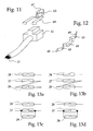
- the spring element shown in Figure 11 for mounting the sensor 11 in a T-shaped undercut groove 41 is made in one piece from a spring steel. It has a sensor body 21 peripheral part and a spring part with two teeth 63 which can be brought into engagement with a recess in the side wall of the groove, in particular the narrower and outer part of the T-shaped groove. These depressions can be achieved by pressing the tooth 63 into the aluminum of the piston skirt.
- the parts comprising the sensor body 21 lie in the mounted position between the sensor body and the flange 59. In addition, they can exert a spring force on the sensor which presses it against the bottom of the groove.
- the teeth 63 in the resilient part are pressed by the spring force of this part to the outside. They are in the relaxed state of the spring element at a greater distance from each other than the width of the groove. As a result, they must be approximated against each other during insertion of the spring element into the groove under deformation of the spring parts. With a screwdriver or a special tool, the punched out of the spring steel and folded teeth 63 can be pressed directly opposite each other in the aluminum of the flange 59 and therefore hold there form-fitting.
- FIG. 1 A variant of such a spring element is shown in FIG. This also has flanges 69, a part surrounding the sensor body and two spring parts with teeth 63. However, these are here in front of and behind the sensor.
- FIG. 13 shows four circuit diagrams in which the three reed contacts 15, 16, 17 are combined into two conductor tracks and can have three distinguishable switching patterns. Apart from these schematics, it is also possible to tap off the three reed contacts individually and to analyze the switching state of the sensor with a downstream logic.
- the first reed contact 15 and the third reed contact 17 are connected in series. In the series connection, it is necessary for the first reed contact to be a make contact and the third a normally closed contact to obtain a clear sensor signal.
- the second reed contact may be an opener (FIG. 13b) or a make contact (FIG. 13a).
- the first reed contact 15 and the third reed contact 17 are connected in parallel. This requires that the first reed contact 15 is an opener and the third reed contact 17 is a make contact, so that unique sensor signals are generated.
- the second reed contact can again be an opener or a closer.
- each reed contact can be an opener or a make contact independently of the other one.
- the logic circuit must be designed accordingly so that the open position and closed position of the individual reed contacts are interpreted correctly.
Landscapes
- Physics & Mathematics (AREA)
- General Physics & Mathematics (AREA)
- Measurement Of Length, Angles, Or The Like Using Electric Or Magnetic Means (AREA)
- Actuator (AREA)
- Switches That Are Operated By Magnetic Or Electric Fields (AREA)
Applications Claiming Priority (1)
| Application Number | Priority Date | Filing Date | Title |
|---|---|---|---|
| CH8822006 | 2006-06-01 |
Publications (3)
| Publication Number | Publication Date |
|---|---|
| EP1862767A2 true EP1862767A2 (fr) | 2007-12-05 |
| EP1862767A3 EP1862767A3 (fr) | 2013-12-04 |
| EP1862767B1 EP1862767B1 (fr) | 2015-05-27 |
Family
ID=38562927
Family Applications (1)
| Application Number | Title | Priority Date | Filing Date |
|---|---|---|---|
| EP07405110.3A Active EP1862767B1 (fr) | 2006-06-01 | 2007-04-11 | Capteur de position de sécurité pour cylindre, cylindre doté d'un tel capteur de position |
Country Status (4)
| Country | Link |
|---|---|
| US (2) | US7852067B2 (fr) |
| EP (1) | EP1862767B1 (fr) |
| JP (1) | JP5171110B2 (fr) |
| CN (1) | CN101082478B (fr) |
Cited By (2)
| Publication number | Priority date | Publication date | Assignee | Title |
|---|---|---|---|---|
| DE102016205069A1 (de) | 2016-03-29 | 2017-10-05 | Contitech Luftfedersysteme Gmbh | Positionsbestimmungseinrichtung für Kolben-Zylinder-Anordnungen |
| EP4197704A1 (fr) | 2021-12-17 | 2023-06-21 | Göpel electronic GmbH | Détecteur de position |
Families Citing this family (11)
| Publication number | Priority date | Publication date | Assignee | Title |
|---|---|---|---|---|
| CH702223B1 (de) * | 2006-06-01 | 2011-05-31 | Elesta Relays Gmbh | Set mit einem Positionssensor und einem Erregerteil. |
| JP2011505574A (ja) | 2007-12-03 | 2011-02-24 | シーティーエス・コーポレーション | リニアポジションセンサー |
| CN202101680U (zh) | 2008-11-26 | 2012-01-04 | Cts公司 | 带有抗转器的线性位置传感器 |
| DE112010004761T5 (de) | 2009-12-09 | 2012-11-29 | Cts Corporation | Antriebs- und Sensoranordnung |
| US9435630B2 (en) | 2010-12-08 | 2016-09-06 | Cts Corporation | Actuator and linear position sensor assembly |
| CN102254643B (zh) * | 2011-05-17 | 2013-08-14 | 芜湖飞云电工机械有限公司 | 一种电缆钢包机钢带锁紧装置 |
| CN102680217B (zh) * | 2012-04-20 | 2015-02-18 | 杰锋汽车动力系统股份有限公司 | 一种单向阀开启压力检测装置 |
| CN109922646B (zh) * | 2019-03-18 | 2020-10-16 | 南京工业职业技术学院 | 屏蔽簧片 |
| JP7120264B2 (ja) * | 2020-02-14 | 2022-08-17 | Tdk株式会社 | 位置検出装置、レンズモジュールおよび撮像装置 |
| WO2021195232A1 (fr) * | 2020-03-24 | 2021-09-30 | Stabilus Gmbh | Ensembles pistons et procédés d'utilisation de ceux-ci |
| CN111403193A (zh) * | 2020-04-16 | 2020-07-10 | 鞍山电磁阀有限责任公司 | 行程开关 |
Family Cites Families (20)
| Publication number | Priority date | Publication date | Assignee | Title |
|---|---|---|---|---|
| US2877361A (en) * | 1957-04-12 | 1959-03-10 | Holmes Electric Protective Com | Burglar alarm system |
| JPS5441143B2 (fr) * | 1974-02-04 | 1979-12-06 | ||
| DE7635587U1 (de) * | 1976-11-11 | 1977-03-10 | Festo-Maschinenfabrik Gottlieb Stoll, 7300 Esslingen | Pneumatische oder hydraulische Kolbenzylinder-Einheit |
| JPS54158991U (fr) * | 1978-04-28 | 1979-11-06 | ||
| DE3240351A1 (de) * | 1982-10-30 | 1984-05-03 | Wabco Westinghouse Steuerungstechnik GmbH & Co, 3000 Hannover | Druckmittelbetaetigter arbeitszylinder |
| DE3410858A1 (de) * | 1984-03-23 | 1985-10-03 | Alfred Teves Gmbh, 6000 Frankfurt | Elektrischer schalter |
| US4967792A (en) * | 1984-07-18 | 1990-11-06 | Magee Anthony J | Sensing the open and/or closed condition of valves |
| JPS63122902A (ja) * | 1986-11-13 | 1988-05-26 | Ckd Controls Ltd | 移動体の位置確認装置 |
| US4755636A (en) * | 1987-06-24 | 1988-07-05 | Taiyo, Ltd. | Piston position detecting device for fluid pressure cylinder |
| JP2529329B2 (ja) * | 1988-01-18 | 1996-08-28 | シーケーディ 株式会社 | 磁気近接センサ |
| DE8901770U1 (de) * | 1989-02-15 | 1990-07-26 | Schaltbau GmbH, 8000 München | Stellantrieb |
| DE9115266U1 (de) * | 1991-12-09 | 1992-02-06 | alfasystem GmbH Herstellung und Vertrieb von elektronischen Sicherheitssystemen, 82110 Germering | Öffnungsmelder |
| JP2601918Y2 (ja) * | 1993-09-07 | 1999-12-13 | 株式会社コガネイ | 流体圧シリンダの位置検出装置 |
| JP2857332B2 (ja) * | 1994-10-17 | 1999-02-17 | シーケーディ株式会社 | ピストン位置検出装置 |
| DE19717804A1 (de) * | 1997-04-26 | 1998-11-05 | Michael Schich | Go-Kart-Schaltgetriebe |
| JP4029506B2 (ja) * | 1999-01-25 | 2008-01-09 | 松下電器産業株式会社 | ガス遮断装置 |
| JP4235979B2 (ja) * | 1999-07-01 | 2009-03-11 | 綜合警備保障株式会社 | マグネットスイッチ |
| JP2002211626A (ja) * | 2001-01-12 | 2002-07-31 | Toska Co Ltd | 巻装バンド |
| US6642704B2 (en) * | 2001-09-28 | 2003-11-04 | Eaton Corporation | Device for sensing electrical current and housing therefor |
| JP4093477B2 (ja) * | 2003-09-08 | 2008-06-04 | 株式会社近畿システムプラン | インシュロック |
-
2007
- 2007-04-11 EP EP07405110.3A patent/EP1862767B1/fr active Active
- 2007-05-28 JP JP2007140199A patent/JP5171110B2/ja not_active Expired - Fee Related
- 2007-05-31 US US11/806,414 patent/US7852067B2/en not_active Expired - Fee Related
- 2007-06-01 CN CN2007101064759A patent/CN101082478B/zh not_active Expired - Fee Related
-
2010
- 2010-11-12 US US12/944,829 patent/US20110062949A1/en not_active Abandoned
Cited By (4)
| Publication number | Priority date | Publication date | Assignee | Title |
|---|---|---|---|---|
| DE102016205069A1 (de) | 2016-03-29 | 2017-10-05 | Contitech Luftfedersysteme Gmbh | Positionsbestimmungseinrichtung für Kolben-Zylinder-Anordnungen |
| EP4197704A1 (fr) | 2021-12-17 | 2023-06-21 | Göpel electronic GmbH | Détecteur de position |
| DE102021133643A1 (de) | 2021-12-17 | 2023-06-22 | Göpel electronic GmbH | Positionsdetektor |
| DE102021133643B4 (de) | 2021-12-17 | 2024-01-25 | Göpel electronic GmbH | Positionsdetektor |
Also Published As
| Publication number | Publication date |
|---|---|
| JP5171110B2 (ja) | 2013-03-27 |
| CN101082478A (zh) | 2007-12-05 |
| CN101082478B (zh) | 2010-12-08 |
| EP1862767A3 (fr) | 2013-12-04 |
| US20070279048A1 (en) | 2007-12-06 |
| US20110062949A1 (en) | 2011-03-17 |
| EP1862767B1 (fr) | 2015-05-27 |
| US7852067B2 (en) | 2010-12-14 |
| JP2007324129A (ja) | 2007-12-13 |
Similar Documents
| Publication | Publication Date | Title |
|---|---|---|
| EP1862767B1 (fr) | Capteur de position de sécurité pour cylindre, cylindre doté d'un tel capteur de position | |
| EP3220781B1 (fr) | Dispositif de fermeture permettant de fixer un appareil électronique à un dispositif de retenue | |
| EP3362801B1 (fr) | Module de détection pour un capteur de courant, et procédé de montage d'un module de détection | |
| EP0747603A1 (fr) | Assemblage pour panneaux | |
| EP0937311A1 (fr) | Dispositif de fixation d'un capteur de distance sur un vehicule automobile | |
| EP1249681B1 (fr) | Dispositif magnétostrictif de mesure de déplacement | |
| EP1995829B1 (fr) | Système de codage pour connecteurs à fiches subminiatures D | |
| DE602004013416T2 (de) | Linearstellelement | |
| DE3628211A1 (de) | Komponentenhalterung | |
| EP0292743B1 (fr) | Ferme-porte avec dispositif indicateur de la force de fermeture | |
| DE102007062099B4 (de) | Positionserfassungseinrichtung | |
| DE102012006264A1 (de) | In einer T-Nut befestigbarer Zylinderschalter, der aus dem Klemmzustand lösbar ist | |
| EP0207270A2 (fr) | Dispositif de commutation fonctionnant sans contact par détecteur de proximité | |
| EP3152070B1 (fr) | Accouplement d'attelage | |
| WO2010037442A1 (fr) | Commutateur | |
| DE102014102793A1 (de) | Befestigungselement für einen Stromsensor | |
| DE102019106365A1 (de) | Elektromagnetische Stellanordnung | |
| EP0943824A1 (fr) | Dispositif de fixation | |
| DE102007020313B4 (de) | Vorrichtung zum Überwachen des Zustandes einer Schutzeinrichtung einer Maschine | |
| WO2010006762A1 (fr) | Interrupteur à bascule | |
| DE3209550C2 (de) | Gehäuse für elektrotechnische Geräte | |
| DE69305423T2 (de) | Verkehrszeichen | |
| DE20003512U1 (de) | Drehwinkelsensor | |
| DE19503075A1 (de) | Bewegungssensor | |
| DE3309775A1 (de) | Peripheriegeraet fuer werkzeugmaschinen, wie messgeraete, werkzeugeinstellgeraete o. dgl. |
Legal Events
| Date | Code | Title | Description |
|---|---|---|---|
| PUAI | Public reference made under article 153(3) epc to a published international application that has entered the european phase |
Free format text: ORIGINAL CODE: 0009012 |
|
| AK | Designated contracting states |
Kind code of ref document: A2 Designated state(s): AT BE BG CH CY CZ DE DK EE ES FI FR GB GR HU IE IS IT LI LT LU LV MC MT NL PL PT RO SE SI SK TR |
|
| AX | Request for extension of the european patent |
Extension state: AL BA HR MK YU |
|
| RAP1 | Party data changed (applicant data changed or rights of an application transferred) |
Owner name: PILZ AUSLANDSBETEILIGUNGEN GMBH |
|
| RIC1 | Information provided on ipc code assigned before grant |
Ipc: G01D 5/251 20060101ALI20130709BHEP Ipc: G01D 5/06 20060101AFI20130709BHEP |
|
| PUAL | Search report despatched |
Free format text: ORIGINAL CODE: 0009013 |
|
| AK | Designated contracting states |
Kind code of ref document: A3 Designated state(s): AT BE BG CH CY CZ DE DK EE ES FI FR GB GR HU IE IS IT LI LT LU LV MC MT NL PL PT RO SE SI SK TR |
|
| AX | Request for extension of the european patent |
Extension state: AL BA HR MK RS |
|
| RIC1 | Information provided on ipc code assigned before grant |
Ipc: G01D 5/06 20060101AFI20131028BHEP Ipc: G01D 5/251 20060101ALI20131028BHEP |
|
| 17P | Request for examination filed |
Effective date: 20140521 |
|
| RBV | Designated contracting states (corrected) |
Designated state(s): AT BE BG CH CY CZ DE DK EE ES FI FR GB GR HU IE IS IT LI LT LU LV MC MT NL PL PT RO SE SI SK TR |
|
| RBV | Designated contracting states (corrected) |
Designated state(s): AT BE BG CH CY CZ DE DK EE ES FI FR GB GR HU IE IS IT LI LT LU LV MC MT NL PL PT RO SE SI SK TR |
|
| AKX | Designation fees paid |
Designated state(s): AT BE BG CH CY CZ DE DK EE ES FI FR GB GR HU IE IS IT LI LT LU LV MC MT NL PL PT RO SE SI SK TR |
|
| GRAP | Despatch of communication of intention to grant a patent |
Free format text: ORIGINAL CODE: EPIDOSNIGR1 |
|
| INTG | Intention to grant announced |
Effective date: 20141127 |
|
| RIN1 | Information on inventor provided before grant (corrected) |
Inventor name: SCHMID, MAX Inventor name: MAHDI, FOUAD |
|
| GRAS | Grant fee paid |
Free format text: ORIGINAL CODE: EPIDOSNIGR3 |
|
| GRAA | (expected) grant |
Free format text: ORIGINAL CODE: 0009210 |
|
| AK | Designated contracting states |
Kind code of ref document: B1 Designated state(s): AT BE BG CH CY CZ DE DK EE ES FI FR GB GR HU IE IS IT LI LT LU LV MC MT NL PL PT RO SE SI SK TR |
|
| REG | Reference to a national code |
Ref country code: GB Ref legal event code: FG4D Free format text: NOT ENGLISH |
|
| REG | Reference to a national code |
Ref country code: CH Ref legal event code: EP |
|
| REG | Reference to a national code |
Ref country code: AT Ref legal event code: REF Ref document number: 729102 Country of ref document: AT Kind code of ref document: T Effective date: 20150615 |
|
| REG | Reference to a national code |
Ref country code: IE Ref legal event code: FG4D Free format text: LANGUAGE OF EP DOCUMENT: GERMAN |
|
| REG | Reference to a national code |
Ref country code: CH Ref legal event code: NV Representative=s name: RIEDERER HASLER AND PARTNER PATENTANWAELTE AG, LI |
|
| REG | Reference to a national code |
Ref country code: DE Ref document number: 502007013946 Country of ref document: DE Effective date: 20150709 Ref legal event code: R096 |
|
| REG | Reference to a national code |
Ref country code: LT Ref legal event code: MG4D |
|
| PG25 | Lapsed in a contracting state [announced via postgrant information from national office to epo] |
Ref country code: FI Free format text: LAPSE BECAUSE OF FAILURE TO SUBMIT A TRANSLATION OF THE DESCRIPTION OR TO PAY THE FEE WITHIN THE PRESCRIBED TIME-LIMIT Effective date: 20150527 Ref country code: PT Free format text: LAPSE BECAUSE OF FAILURE TO SUBMIT A TRANSLATION OF THE DESCRIPTION OR TO PAY THE FEE WITHIN THE PRESCRIBED TIME-LIMIT Effective date: 20150928 Ref country code: ES Free format text: LAPSE BECAUSE OF FAILURE TO SUBMIT A TRANSLATION OF THE DESCRIPTION OR TO PAY THE FEE WITHIN THE PRESCRIBED TIME-LIMIT Effective date: 20150527 Ref country code: LT Free format text: LAPSE BECAUSE OF FAILURE TO SUBMIT A TRANSLATION OF THE DESCRIPTION OR TO PAY THE FEE WITHIN THE PRESCRIBED TIME-LIMIT Effective date: 20150527 |
|
| REG | Reference to a national code |
Ref country code: NL Ref legal event code: MP Effective date: 20150527 |
|
| PG25 | Lapsed in a contracting state [announced via postgrant information from national office to epo] |
Ref country code: LV Free format text: LAPSE BECAUSE OF FAILURE TO SUBMIT A TRANSLATION OF THE DESCRIPTION OR TO PAY THE FEE WITHIN THE PRESCRIBED TIME-LIMIT Effective date: 20150527 Ref country code: IS Free format text: LAPSE BECAUSE OF FAILURE TO SUBMIT A TRANSLATION OF THE DESCRIPTION OR TO PAY THE FEE WITHIN THE PRESCRIBED TIME-LIMIT Effective date: 20150927 Ref country code: GR Free format text: LAPSE BECAUSE OF FAILURE TO SUBMIT A TRANSLATION OF THE DESCRIPTION OR TO PAY THE FEE WITHIN THE PRESCRIBED TIME-LIMIT Effective date: 20150828 Ref country code: BG Free format text: LAPSE BECAUSE OF FAILURE TO SUBMIT A TRANSLATION OF THE DESCRIPTION OR TO PAY THE FEE WITHIN THE PRESCRIBED TIME-LIMIT Effective date: 20150827 |
|
| PG25 | Lapsed in a contracting state [announced via postgrant information from national office to epo] |
Ref country code: DK Free format text: LAPSE BECAUSE OF FAILURE TO SUBMIT A TRANSLATION OF THE DESCRIPTION OR TO PAY THE FEE WITHIN THE PRESCRIBED TIME-LIMIT Effective date: 20150527 Ref country code: EE Free format text: LAPSE BECAUSE OF FAILURE TO SUBMIT A TRANSLATION OF THE DESCRIPTION OR TO PAY THE FEE WITHIN THE PRESCRIBED TIME-LIMIT Effective date: 20150527 |
|
| PG25 | Lapsed in a contracting state [announced via postgrant information from national office to epo] |
Ref country code: RO Free format text: LAPSE BECAUSE OF NON-PAYMENT OF DUE FEES Effective date: 20150527 Ref country code: PL Free format text: LAPSE BECAUSE OF FAILURE TO SUBMIT A TRANSLATION OF THE DESCRIPTION OR TO PAY THE FEE WITHIN THE PRESCRIBED TIME-LIMIT Effective date: 20150527 Ref country code: CZ Free format text: LAPSE BECAUSE OF FAILURE TO SUBMIT A TRANSLATION OF THE DESCRIPTION OR TO PAY THE FEE WITHIN THE PRESCRIBED TIME-LIMIT Effective date: 20150527 Ref country code: SK Free format text: LAPSE BECAUSE OF FAILURE TO SUBMIT A TRANSLATION OF THE DESCRIPTION OR TO PAY THE FEE WITHIN THE PRESCRIBED TIME-LIMIT Effective date: 20150527 |
|
| REG | Reference to a national code |
Ref country code: DE Ref legal event code: R097 Ref document number: 502007013946 Country of ref document: DE |
|
| PLBE | No opposition filed within time limit |
Free format text: ORIGINAL CODE: 0009261 |
|
| STAA | Information on the status of an ep patent application or granted ep patent |
Free format text: STATUS: NO OPPOSITION FILED WITHIN TIME LIMIT |
|
| REG | Reference to a national code |
Ref country code: FR Ref legal event code: PLFP Year of fee payment: 10 |
|
| 26N | No opposition filed |
Effective date: 20160301 |
|
| PG25 | Lapsed in a contracting state [announced via postgrant information from national office to epo] |
Ref country code: SI Free format text: LAPSE BECAUSE OF FAILURE TO SUBMIT A TRANSLATION OF THE DESCRIPTION OR TO PAY THE FEE WITHIN THE PRESCRIBED TIME-LIMIT Effective date: 20150527 |
|
| PG25 | Lapsed in a contracting state [announced via postgrant information from national office to epo] |
Ref country code: BE Free format text: LAPSE BECAUSE OF NON-PAYMENT OF DUE FEES Effective date: 20160430 |
|
| GBPC | Gb: european patent ceased through non-payment of renewal fee |
Effective date: 20160411 |
|
| PG25 | Lapsed in a contracting state [announced via postgrant information from national office to epo] |
Ref country code: LU Free format text: LAPSE BECAUSE OF FAILURE TO SUBMIT A TRANSLATION OF THE DESCRIPTION OR TO PAY THE FEE WITHIN THE PRESCRIBED TIME-LIMIT Effective date: 20160411 |
|
| REG | Reference to a national code |
Ref country code: IE Ref legal event code: MM4A |
|
| PG25 | Lapsed in a contracting state [announced via postgrant information from national office to epo] |
Ref country code: GB Free format text: LAPSE BECAUSE OF NON-PAYMENT OF DUE FEES Effective date: 20160411 |
|
| REG | Reference to a national code |
Ref country code: FR Ref legal event code: PLFP Year of fee payment: 11 |
|
| PG25 | Lapsed in a contracting state [announced via postgrant information from national office to epo] |
Ref country code: IE Free format text: LAPSE BECAUSE OF NON-PAYMENT OF DUE FEES Effective date: 20160411 |
|
| REG | Reference to a national code |
Ref country code: AT Ref legal event code: MM01 Ref document number: 729102 Country of ref document: AT Kind code of ref document: T Effective date: 20160411 |
|
| PG25 | Lapsed in a contracting state [announced via postgrant information from national office to epo] |
Ref country code: NL Free format text: LAPSE BECAUSE OF FAILURE TO SUBMIT A TRANSLATION OF THE DESCRIPTION OR TO PAY THE FEE WITHIN THE PRESCRIBED TIME-LIMIT Effective date: 20150527 Ref country code: SE Free format text: LAPSE BECAUSE OF FAILURE TO SUBMIT A TRANSLATION OF THE DESCRIPTION OR TO PAY THE FEE WITHIN THE PRESCRIBED TIME-LIMIT Effective date: 20150527 |
|
| PG25 | Lapsed in a contracting state [announced via postgrant information from national office to epo] |
Ref country code: AT Free format text: LAPSE BECAUSE OF NON-PAYMENT OF DUE FEES Effective date: 20160411 |
|
| REG | Reference to a national code |
Ref country code: FR Ref legal event code: PLFP Year of fee payment: 12 |
|
| PG25 | Lapsed in a contracting state [announced via postgrant information from national office to epo] |
Ref country code: CY Free format text: LAPSE BECAUSE OF FAILURE TO SUBMIT A TRANSLATION OF THE DESCRIPTION OR TO PAY THE FEE WITHIN THE PRESCRIBED TIME-LIMIT Effective date: 20150527 Ref country code: HU Free format text: LAPSE BECAUSE OF FAILURE TO SUBMIT A TRANSLATION OF THE DESCRIPTION OR TO PAY THE FEE WITHIN THE PRESCRIBED TIME-LIMIT; INVALID AB INITIO Effective date: 20070411 |
|
| PG25 | Lapsed in a contracting state [announced via postgrant information from national office to epo] |
Ref country code: TR Free format text: LAPSE BECAUSE OF FAILURE TO SUBMIT A TRANSLATION OF THE DESCRIPTION OR TO PAY THE FEE WITHIN THE PRESCRIBED TIME-LIMIT Effective date: 20150527 Ref country code: MT Free format text: LAPSE BECAUSE OF FAILURE TO SUBMIT A TRANSLATION OF THE DESCRIPTION OR TO PAY THE FEE WITHIN THE PRESCRIBED TIME-LIMIT Effective date: 20150527 Ref country code: MC Free format text: LAPSE BECAUSE OF FAILURE TO SUBMIT A TRANSLATION OF THE DESCRIPTION OR TO PAY THE FEE WITHIN THE PRESCRIBED TIME-LIMIT Effective date: 20150527 |
|
| PGFP | Annual fee paid to national office [announced via postgrant information from national office to epo] |
Ref country code: DE Payment date: 20250422 Year of fee payment: 19 |
|
| PGFP | Annual fee paid to national office [announced via postgrant information from national office to epo] |
Ref country code: IT Payment date: 20250424 Year of fee payment: 19 |
|
| PGFP | Annual fee paid to national office [announced via postgrant information from national office to epo] |
Ref country code: FR Payment date: 20250423 Year of fee payment: 19 |
|
| PGFP | Annual fee paid to national office [announced via postgrant information from national office to epo] |
Ref country code: CH Payment date: 20250501 Year of fee payment: 19 |