EP1863985B1 - Systeme de coffrage - Google Patents
Systeme de coffrage Download PDFInfo
- Publication number
- EP1863985B1 EP1863985B1 EP05823053.3A EP05823053A EP1863985B1 EP 1863985 B1 EP1863985 B1 EP 1863985B1 EP 05823053 A EP05823053 A EP 05823053A EP 1863985 B1 EP1863985 B1 EP 1863985B1
- Authority
- EP
- European Patent Office
- Prior art keywords
- formwork
- formwork support
- support
- formwork system
- guide
- Prior art date
- Legal status (The legal status is an assumption and is not a legal conclusion. Google has not performed a legal analysis and makes no representation as to the accuracy of the status listed.)
- Expired - Lifetime
Links
Images




Classifications
-
- B—PERFORMING OPERATIONS; TRANSPORTING
- B28—WORKING CEMENT, CLAY, OR STONE
- B28B—SHAPING CLAY OR OTHER CERAMIC COMPOSITIONS; SHAPING SLAG; SHAPING MIXTURES CONTAINING CEMENTITIOUS MATERIAL, e.g. PLASTER
- B28B7/00—Moulds; Cores; Mandrels
- B28B7/0002—Auxiliary parts or elements of the mould
- B28B7/0014—Fastening means for mould parts, e.g. for attaching mould walls on mould tables; Mould clamps
- B28B7/0017—Fastening means for mould parts, e.g. for attaching mould walls on mould tables; Mould clamps for attaching mould walls on mould tables
-
- B—PERFORMING OPERATIONS; TRANSPORTING
- B28—WORKING CEMENT, CLAY, OR STONE
- B28B—SHAPING CLAY OR OTHER CERAMIC COMPOSITIONS; SHAPING SLAG; SHAPING MIXTURES CONTAINING CEMENTITIOUS MATERIAL, e.g. PLASTER
- B28B7/00—Moulds; Cores; Mandrels
- B28B7/0002—Auxiliary parts or elements of the mould
- B28B7/0014—Fastening means for mould parts, e.g. for attaching mould walls on mould tables; Mould clamps
- B28B7/002—Fastening means for mould parts, e.g. for attaching mould walls on mould tables; Mould clamps using magnets
-
- E—FIXED CONSTRUCTIONS
- E04—BUILDING
- E04G—SCAFFOLDING; FORMS; SHUTTERING; BUILDING IMPLEMENTS OR AIDS, OR THEIR USE; HANDLING BUILDING MATERIALS ON THE SITE; REPAIRING, BREAKING-UP OR OTHER WORK ON EXISTING BUILDINGS
- E04G17/00—Connecting or other auxiliary members for forms, falsework structures, or shutterings
- E04G17/14—Bracing or strutting arrangements for formwalls; Devices for aligning forms
-
- Y—GENERAL TAGGING OF NEW TECHNOLOGICAL DEVELOPMENTS; GENERAL TAGGING OF CROSS-SECTIONAL TECHNOLOGIES SPANNING OVER SEVERAL SECTIONS OF THE IPC; TECHNICAL SUBJECTS COVERED BY FORMER USPC CROSS-REFERENCE ART COLLECTIONS [XRACs] AND DIGESTS
- Y10—TECHNICAL SUBJECTS COVERED BY FORMER USPC
- Y10S—TECHNICAL SUBJECTS COVERED BY FORMER USPC CROSS-REFERENCE ART COLLECTIONS [XRACs] AND DIGESTS
- Y10S425/00—Plastic article or earthenware shaping or treating: apparatus
- Y10S425/033—Magnet
Definitions
- the stiffness and stability of the formwork support can be further increased when the stiffening element connects the legs of the profile with each other.
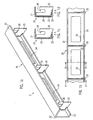
- FIG. 1 a shows an overall view of the formwork support 2 of the first embodiment in an overall view.
- the formwork support 2 of the first exemplary embodiment comprises an elongated profile body 20 of substantially C-shaped cross section with an upper leg 21, a lower leg 22 and a back 23 connecting the legs 21, 22.
- the upper and lower legs 21, 22 are in each case perpendicular from the back 23 of the C-profile 20 from, as in the sectional views of Figures 1c and 1d is shown, wherein the legs 21, 22 are of different lengths and the upper leg 21 is longer or protrudes further from the back 23 than the lower leg 22.
- the C-shaped profile body 20 may have a substantially arbitrary length.
- FIG. 2b shows a front view of the mounting bracket 27, but without intermediate piece 11 and formwork part 10th
- the magnetic device 3 comprises a substantially cuboid magnetic body 30 on the upper side of which a substantially rectangular metal plate 35 is screwed and / or welded.
- the outline of the metal plate 35 corresponds in plan view substantially the outline of the magnetic body 30, wherein the metal plate 35 is rotated by 90 ° relative to the magnetic body 30, and wherein a broad edge side of the metal plate 35 is aligned with a longitudinal edge side of the cuboid magnetic body 30 and the opposite End of the metal plate 35 protrudes beyond the opposite longitudinal edge side of the magnetic body 30.
- a total of four substantially stepped cylindrical bores 31 are provided perpendicular to the underside of the magnet body 30.
- step-shaped, substantially cylindrical bolts 33 which form the feet 33 of the magnetic device 3, inserted.
- the feet 33 have, as in the Figures 3f and 3g is shown, a substantially T-shaped cross-section, wherein the contour of the wide head portion is substantially matched to the contour of the receiving bore 31.
- a substantially annular cover 34 is inserted.
- the lid 34 has a through-opening which is substantially matched to the diameter of the thinner portion of the foot 33, the lid retaining the broad head portion of the foot 33, so that the leg 33, biased by a spring element 32, will lift the magnet device 3 from the formwork support 4 can not fall out of the bore 31.
- FIGS. 3b, 3c and 3f show the magnetic device 3, wherein the magnetic body 30 is in a relation to the formwork support 4 raised position.
- a simplified representation is chosen to illustrate the bores 31, spring elements 32 and feet 33.
- the detailed representation is in the Figures 3f and 3g to see.
- the feet 33 protrude beyond the underside of the magnetic body 30, so that the underside of the magnetic body 30 is spaced from the surface of the shuttering pad 4.
- the magnetic force of attraction of the magnet body 30 on the formwork support is substantially negligible in the raised position of the magnet body 30 and the magnet apparatus 3, respectively, so that the force exerted on the formwork support 4 substantially corresponds to the weight force of the magnet apparatus 3.
- FIG. 3c shows a sectional view of the magnetic device 3 in the raised position and FIG. 3f an associated detail view of the bore 31, the spring element 32, the foot 33 and the lid 34 of the magnetic device.
- Figures 3d, 3e and 3g show the magnetic body 30 and the magnetic device 3 in a lowered position relative to the shuttering pad 4, wherein the feet 33 are completely in the receptacles 31 and the magnetic body 30, the full magnetic force unfolded.
- the magnetic force 30 or the entire magnetic device 3 developed in interaction with the formwork support 4 pulls down perpendicular to the formwork support 4.
- the eccentric 37 is located in a position in which no peripheral portion of the eccentric 37 protrudes beyond the underside of the magnetic body 30.
- FIG. 3g is shown in detail, as a foot 33 is pressed against the force of the spring member 32 into the interior of the bore 31 and is completely received in the interior of the bore 31.
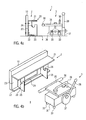
- the formwork support 2 is brought into its intended position on the formwork support 4 with the formwork part 10 screwed on.
- the free ends of the metal plate 36 welded to the metal plate 35 are introduced from above into the U-shaped, groove-like and elongated receiving slots 26 of the receiving portions 25.
- the groove-like receiving slots 26 are open at the top and serve to be arranged, free ends of the metal rod 36, which are also referred to below as guide portions 36, as a sliding guide.
- the free ends of the metal rod 36 and the guide portions are movably received and in the direction of movement of the magnetic body when transferring from the raised to the lowered position slidably feasible.
- the groove-like receptacle 26 can, as shown, be open towards the upper end or be closed in order to non-detachably couple the magnetic device 3 to the formwork support 2.
- the groove-like receptacle 26 open at the top and the magnetic device 3 is detachably coupled to the formwork support.
- raised position of the magnetic body 30 and the magnetic device 3 the magnetic device 3 and the formwork support 2 are already coupled and displaceable together on the formwork support 4.
- the force acting on the formwork base 4 magnetic force of the magnetic body 30 is negligible, so that when moving the formwork system, ie shuttering 2 with coupled magnetic device 3, only the force caused by the weight of friction of both elements is overcome.
- FIGS. 5a to 5f show a preferred application of the shuttering system according to the invention with magnetic device 3 and as the fastening means 27 executed Formwork support 2 of the second embodiment, which is substantially the same as previously FIGS. 4a to 4f similar to the application described.
- Formwork support 2 of the first embodiment of the mounting bracket 27 is provided specifically for mounting a single magnetic device 3.
- a formwork member 10 is bolted to the mounting bracket 27 at the back and placed on the formwork support 4 in its intended position.
- the magnetic device 3 is decoupled from the mounting bracket 27.
- the free ends of the metal bar 36 and the guide portions are inserted from above into the groove-like receiving slots 26 in the receiving portions 25 of the mounting bracket 27 so that the guide portions 36 engage with the legs or receiving portions 25 of the mounting bracket 27 are located.
- the magnetic device 3 is displaceable relative to the formwork support 2 for transferring the magnet body 30 between the raised and lowered positions.
- the same magnetic device 3 can be used in conjunction with the formwork support 2 of the first embodiment as well as with the formwork support 2 formed as a mounting bracket 27 of the second embodiment.
- the formwork support 2 of the first embodiment can also be used independently of the magnetic device 3.
Landscapes
- Engineering & Computer Science (AREA)
- Mechanical Engineering (AREA)
- Manufacturing & Machinery (AREA)
- Chemical & Material Sciences (AREA)
- Ceramic Engineering (AREA)
- Architecture (AREA)
- Civil Engineering (AREA)
- Structural Engineering (AREA)
- Moulds, Cores, Or Mandrels (AREA)
- Forms Removed On Construction Sites Or Auxiliary Members Thereof (AREA)
Claims (20)
- Système de coffrage (1) avec une poutrelle de coffrage (2), préférablement pour supporter au moins un élément de coffrage (10), et un dispositif magnétique (3) accouplé de manière mobile à la poutrelle de coffrage (2) pour fixer la position de la poutrelle de coffrage (2) sur un support de coffrage (4), dans lequel le dispositif magnétique (3) comporte un corps magnétique (30) qui peut être transféré entre une position levée, dans laquelle la poutrelle de coffrage (2) peut être déplacée conjointement au dispositif magnétique (3) par rapport au support de coffrage (4), et une position abaissée, dans laquelle le système de coffrage (1) est fixé magnétiquement par rapport au support de coffrage (4), dans lequel le dispositif magnétique (3) peut être déplacé pour transférer le corps magnétique (30) entre la position levée et la position abaissée par rapport à la poutrelle de coffrage (2), caractérisé en ce que le système de coffrage (1) comporte au moins un dispositif de guidage (25, 26, 36) avec au moins une section de guidage (36) et au moins une section de réception (25, 26), dans lequel la section de guidage (36) est engagée de manière amovible avec la section de réception (25, 26), dans lequel le dispositif de guidage (25, 26, 36) comporte un guidage à coulisseau (26) dans lequel la section de guidage (36) peut être guidée de manière glissante lors du transfert du dispositif magnétique entre la position levée et la position abaissée.
- Système de coffrage (1) selon la revendication 1, caractérisé en ce que le dispositif magnétique (3) et la poutrelle de coffrage (2) sont accouplés entre eux de manière amovible.
- Système de coffrage (1) selon l'une des revendications précédentes, caractérisé en ce que le corps magnétique (30) peut être transféré selon un déplacement essentiellement linéaire entre la position levée et la position abaissée.
- Système de coffrage (1) selon l'une des revendications précédentes, caractérisé en ce que la direction du déplacement linaire est essentiellement perpendiculaire au support de coffrage (4).
- Système de coffrage (1) selon l'une des revendications précédentes, caractérisé en ce qu'en position abaissée du corps magnétique (30), le dispositif magnétique (3) exerce une force sur la poutrelle de coffrage (2) pour appliquer celle-ci contre le support de coffrage (4).
- Système de coffrage (1) selon l'une des revendications précédentes, caractérisé en ce que la section de guidage (36) est reliée de façon fixe au corps magnétique (30).
- Système de coffrage (1) selon l'une des revendications précédentes, caractérisé en ce que le dispositif de guidage (25, 26, 26) comporte au moins deux sections de guidage (36) qui font saillie de différents côtés du corps magnétique (30) essentiellement sur un même axe.
- Système de coffrage (1) selon l'une des revendications précédentes, caractérisé en ce que la section de réception (25) comporte préférablement une gorge longitudinale (26), et la section de guidage comporte une projection (36) qui s'engage dans la gorge.
- Système de coffrage (1) selon l'une des revendications précédentes, caractérisé en ce que la gorge (26) est ouverte à une extrémité.
- Système de coffrage (1) selon l'une des revendications précédentes, caractérisé en ce que la poutrelle de coffrage (2) comporte au moins deux sections de réception (25) qui sont espacées entre elles en direction longitudinale de la poutrelle de coffrage (2).
- Système de coffrage (1) selon l'une des revendications précédentes, caractérisé en ce que la poutrelle de coffrage (2) présente un profil longitudinal (20) avec une section essentiellement en forme de C, qui comporte une face arrière (23) et deux ailes (21, 22) qui sortent de la face arrière (23) de manière essentiellement perpendiculaire.
- Système de coffrage (1) selon l'une des revendications précédentes, caractérisé en ce que la poutrelle de coffrage (2) comporte au moins un élément de raidissement (25) essentiellement plat, qui s'étend de manière essentiellement perpendiculaire à la face arrière (23) et/ou perpendiculaire aux ailes (21, 22) du profil (20).
- Système de coffrage (1) selon la revendication 12, caractérisé en ce que l'élément de raidissement (25) connecte les ailes (21, 22) du profil (20) entre elles.
- Système de coffrage (1) selon l'une des revendications précédentes, caractérisé en ce que l'élément de raidissement (25) relie la face arrière (23) du profil (20) avec au moins l'une des ailes (21, 22).
- Système de coffrage (1) selon l'une des revendications précédentes, caractérisé en ce que la poutrelle de coffrage (2) comporte au moins une ouverture (24) sur la face arrière (23) du profil (20), dans la zone comprise entre deux éléments de raidissement (25).
- Système de coffrage (1) selon l'une des revendications précédentes, caractérisé en ce que les ailes (21, 22) du profil (20) présentent des longueurs différentes.
- Système de coffrage (1) selon l'une des revendications précédentes, caractérisé en ce que la poutrelle de coffrage (2) comporte au moins trois sections de réception (25) qui sont espacées préférablement en direction longitudinale de la poutrelle de coffrage (20) de manière sensiblement uniforme.
- Système de coffrage (1) selon l'une des revendications précédentes, caractérisé en ce que la poutrelle de coffrage (2) est constituée comme une cornière de fixation (27).
- Système de coffrage (1) selon l'une des revendications précédentes, caractérisé en ce qu'un dispositif de guidage du guidage à coulisseau (26) est essentiellement perpendiculaire à la direction longitudinale de la poutrelle de coffrage (2).
- Système de coffrage (1) selon l'une des revendications précédentes, caractérisé en ce que le guidage à coulisseau (26) s'étend essentiellement selon une longueur correspondant environ à la moitié de l'espacement des ailes (21, 22) du profil en C.
Priority Applications (1)
| Application Number | Priority Date | Filing Date | Title |
|---|---|---|---|
| PL05823053T PL1863985T3 (pl) | 2005-03-11 | 2005-12-21 | System szalunkowy |
Applications Claiming Priority (2)
| Application Number | Priority Date | Filing Date | Title |
|---|---|---|---|
| DE202005003979U DE202005003979U1 (de) | 2005-03-11 | 2005-03-11 | Schalungssystem |
| PCT/EP2005/013807 WO2006094547A1 (fr) | 2005-03-11 | 2005-12-21 | Systeme de coffrage |
Publications (2)
| Publication Number | Publication Date |
|---|---|
| EP1863985A1 EP1863985A1 (fr) | 2007-12-12 |
| EP1863985B1 true EP1863985B1 (fr) | 2014-04-23 |
Family
ID=36337524
Family Applications (1)
| Application Number | Title | Priority Date | Filing Date |
|---|---|---|---|
| EP05823053.3A Expired - Lifetime EP1863985B1 (fr) | 2005-03-11 | 2005-12-21 | Systeme de coffrage |
Country Status (9)
| Country | Link |
|---|---|
| US (1) | US7887022B2 (fr) |
| EP (1) | EP1863985B1 (fr) |
| AU (1) | AU2005328925B2 (fr) |
| DE (2) | DE202005003979U1 (fr) |
| ES (1) | ES2479069T3 (fr) |
| NZ (1) | NZ561464A (fr) |
| PL (1) | PL1863985T3 (fr) |
| RU (1) | RU2370607C2 (fr) |
| WO (1) | WO2006094547A1 (fr) |
Families Citing this family (14)
| Publication number | Priority date | Publication date | Assignee | Title |
|---|---|---|---|---|
| EP2064030B1 (fr) * | 2006-09-15 | 2013-05-22 | SRB Construction Technologies Pty Ltd. | Agrafeuse magnétique |
| WO2008034166A1 (fr) * | 2006-09-18 | 2008-03-27 | Srb Construction Technologies Pty Ltd | Dispositif de serrage magnétique |
| AU2016208297A1 (en) * | 2006-09-18 | 2016-08-11 | Illinois Tool Works Inc. | A magnetic clamp |
| DE102007028560B4 (de) * | 2007-06-19 | 2011-11-24 | Thomas Laudan | Magneteinrichtung und Schalungseinrichtungen mit Magneteinrichtungen |
| FI125405B (fi) * | 2008-04-29 | 2015-09-30 | Elematic Oyj | Valumuotin laitarakenne |
| FI20105685A7 (fi) * | 2010-06-15 | 2011-12-16 | Elematic Oy Ab | Valumuotin laitayksikkö sekä laitayksikön irrotusyksikkö |
| DE202010010161U1 (de) | 2010-07-13 | 2010-10-14 | Laudan, Thomas | Schalungsträgersystem |
| DE202010014211U1 (de) | 2010-10-12 | 2011-03-10 | Bt Innovation Gmbh | Haltevorrichtung für Schalungsträger |
| DE102011003671A1 (de) | 2011-02-04 | 2012-08-09 | BETA Maschinenbau GmbH & Co. KG | Schalungsträger und Schalungsanordnung |
| US8876096B2 (en) * | 2012-07-05 | 2014-11-04 | The Boeing Company | Method and apparatus for forming an angled flange |
| US10119281B2 (en) * | 2016-05-09 | 2018-11-06 | Illinois Tool Works Inc. | Joint edge assembly and formwork for forming a joint, and method for forming a joint |
| AT520739B1 (de) * | 2018-03-06 | 2019-07-15 | Progress Holding Ag | Schalungsanordnung |
| CN114701049B (zh) * | 2022-05-10 | 2024-04-26 | 山东交通学院 | 一种轻质墙板生产线及堆垛缓存方法 |
| DE202023001742U1 (de) | 2023-08-17 | 2023-10-16 | B.T. Innovation Gmbh | Schalungssystem |
Family Cites Families (23)
| Publication number | Priority date | Publication date | Assignee | Title |
|---|---|---|---|---|
| US1329177A (en) * | 1919-05-17 | 1920-01-27 | John N Heltzel | Concrete-form |
| US1651787A (en) * | 1923-09-25 | 1927-12-06 | Blaw Knox Co | Road rail |
| US3034613A (en) * | 1959-02-16 | 1962-05-15 | Robert E Heltzel | Slide lock for concrete road forms |
| US3170217A (en) * | 1963-12-03 | 1965-02-23 | Symons Mfg Co | Concrete slab form fill-in panel structure and supporting bracket therefor |
| US3319989A (en) * | 1965-02-23 | 1967-05-16 | Charles W Ross | Magnetic supporting and carrying device |
| DE2907508A1 (de) | 1979-02-26 | 1980-09-04 | Magnetfab Bonn Gmbh | Flachhaft-dauermagnet zur fixierung von schalungsteilen |
| DE3402208A1 (de) * | 1984-01-24 | 1985-07-25 | Gesellschaft für Fertigbautechnik mbH, 4600 Dortmund | Palette zur herstellung von flaechenelementen des grosstafelbaus vorzugsweise in beton |
| US4846437A (en) * | 1987-02-12 | 1989-07-11 | Fitzgerald Leonard R | Bracket for supporting concrete formwork |
| US5096155A (en) * | 1987-02-12 | 1992-03-17 | Fitzgerald Leonard R | Concrete form supporting bracket |
| JPH02293104A (ja) * | 1989-05-09 | 1990-12-04 | Ando Kensetsu Kk | コンクリート板製作用の型枠装置 |
| SU1728438A1 (ru) * | 1990-03-23 | 1992-04-23 | Научно-Исследовательский Институт Строительных Конструкций Госстроя Ссср | Узел соединени опалубочных щитов |
| DE4019498C1 (fr) * | 1990-06-19 | 1991-07-25 | Paschal-Werk G. Maier Gmbh, 7619 Steinach, De | |
| US5261635A (en) * | 1991-12-09 | 1993-11-16 | Symons Corporation | Slab joint system and apparatus for joining concrete slabs in side-by-side relation |
| US5656194A (en) * | 1995-06-14 | 1997-08-12 | Superior Walls Of America, Ltd. | Assembly jig for prefabricated concrete walls |
| DE29707436U1 (de) * | 1997-04-25 | 1997-09-25 | Max Frank Gmbh & Co Kg, 94339 Leiblfing | Fixiersystem für Abschalelemente sowie Fixierleiste zur Verwendung bei diesem System |
| JP4139923B2 (ja) * | 1997-05-13 | 2008-08-27 | ジュリウス ブルム ゲゼルシャフト エム.ビー.エイチ. | 家具用金具 |
| FI3486U1 (fi) * | 1998-03-27 | 1998-07-23 | Addtek Res & Dev Oy Ab | Valumuotin irrotettava laitajärjestelmä |
| FI4258U1 (fi) * | 1999-08-09 | 1999-12-15 | Addtek Res & Dev Oy Ab | Valumuotin irrotettava laitajärjestelmä |
| JP2001129815A (ja) * | 1999-11-04 | 2001-05-15 | Ando Corp | プレハブコンクリート直方体成形用のマグネット固定型枠 |
| DE19961062A1 (de) * | 1999-12-17 | 2001-06-28 | Betoratio Gmbh | Schalungssystem |
| US6536737B1 (en) * | 2000-08-18 | 2003-03-25 | Wade M. Davis | Concrete form brace |
| FI4973U1 (fi) * | 2001-02-16 | 2001-06-27 | Addtek Res & Dev Oy Ab | Magneettiyksikkö valumuotin laitaa varten |
| EP1386045A4 (fr) * | 2001-04-02 | 2004-07-07 | Retail & Commercial Properties | Dispositif de support |
-
2005
- 2005-03-11 DE DE202005003979U patent/DE202005003979U1/de not_active Expired - Lifetime
- 2005-12-21 RU RU2007134910/03A patent/RU2370607C2/ru active
- 2005-12-21 EP EP05823053.3A patent/EP1863985B1/fr not_active Expired - Lifetime
- 2005-12-21 DE DE202005021867U patent/DE202005021867U1/de not_active Expired - Lifetime
- 2005-12-21 US US11/886,163 patent/US7887022B2/en active Active
- 2005-12-21 NZ NZ561464A patent/NZ561464A/en not_active IP Right Cessation
- 2005-12-21 AU AU2005328925A patent/AU2005328925B2/en not_active Ceased
- 2005-12-21 WO PCT/EP2005/013807 patent/WO2006094547A1/fr not_active Ceased
- 2005-12-21 ES ES05823053.3T patent/ES2479069T3/es not_active Expired - Lifetime
- 2005-12-21 PL PL05823053T patent/PL1863985T3/pl unknown
Also Published As
| Publication number | Publication date |
|---|---|
| AU2005328925B2 (en) | 2010-05-13 |
| US20090045316A1 (en) | 2009-02-19 |
| EP1863985A1 (fr) | 2007-12-12 |
| PL1863985T3 (pl) | 2014-09-30 |
| WO2006094547A1 (fr) | 2006-09-14 |
| NZ561464A (en) | 2010-11-26 |
| US7887022B2 (en) | 2011-02-15 |
| DE202005003979U1 (de) | 2006-07-20 |
| AU2005328925A1 (en) | 2006-09-14 |
| RU2370607C2 (ru) | 2009-10-20 |
| ES2479069T3 (es) | 2014-07-23 |
| DE202005021867U1 (de) | 2010-11-04 |
| RU2007134910A (ru) | 2009-04-20 |
Similar Documents
| Publication | Publication Date | Title |
|---|---|---|
| EP1863985B1 (fr) | Systeme de coffrage | |
| DE102004021411B4 (de) | Papierschneidevorrichtung und Halteeinrichtung hierfür | |
| EP2243742A1 (fr) | Plate-forme de levage à ciseaux | |
| DE2624429B2 (de) | Klemmittel | |
| DE2354696A1 (de) | Tragteil fuer bauformen | |
| DE2620545C2 (de) | Schneidwerkzeug zum Ausklinken von Profilbauteilen, insbesondere Fensterrahmenprofilen | |
| DE3915522A1 (de) | Antriebsvorrichtung fuer eine vakuumschaltroehre mit einer kontaktfeder | |
| DE202004012593U1 (de) | Vorrichtung zur Festlegung und/oder Positionierung von Gegenständen in einem Transportbehälter | |
| EP1886896B1 (fr) | Colonne de direction avec accés fasile et mémoire de position | |
| EP0934131A1 (fr) | Machine a cintrer | |
| DE3875819T2 (de) | Biegepresse fuer bleche. | |
| EP1245860B1 (fr) | Dispositif de fixation d'agrafes de jonction de courroie à des courroies transporteuses | |
| EP4279659B1 (fr) | Appareil d'excavation de tranchées pour parois moulées et procédé d'excavation d'une paroi moulée dans le sol | |
| DE60304403T2 (de) | Scherenhubvorrichtung | |
| EP4126485B1 (fr) | Dispositif d'aimant commutable | |
| EP1055487A1 (fr) | Pince avec machoires paralleles | |
| WO2010105591A2 (fr) | Dispositif pour estamper, couper et plier des tôles à l'équerre | |
| EP0873206B1 (fr) | Plieuse | |
| DE102004063580A1 (de) | Möbelstück mit bewegbarem Möbelsegment | |
| DE2546752C3 (de) | Betätigungseinrichtung für zwei abwechselnd zwischen einer ersten und einer zweiten Stellung bewegbare Spurreißer | |
| DE4122567C2 (fr) | ||
| EP1095826B1 (fr) | Dispositif de réglage en hauteur d'un renvoi supérieur ou d'une attache de ceinture de sécurité de véhicule automobile | |
| DE4116940C2 (fr) | ||
| DE3632123C2 (de) | Biegepresse | |
| WO1999050026A2 (fr) | Dispositif pour maintenir, serrer, comprimer et bloquer un objet |
Legal Events
| Date | Code | Title | Description |
|---|---|---|---|
| PUAI | Public reference made under article 153(3) epc to a published international application that has entered the european phase |
Free format text: ORIGINAL CODE: 0009012 |
|
| 17P | Request for examination filed |
Effective date: 20071011 |
|
| AK | Designated contracting states |
Kind code of ref document: A1 Designated state(s): AT BE BG CH CY CZ DE DK EE ES FI FR GB GR HU IE IS IT LI LT LU LV MC NL PL PT RO SE SI SK TR |
|
| RIN1 | Information on inventor provided before grant (corrected) |
Inventor name: SCHREYER, BERND Inventor name: VON LIMBURG, FELIX |
|
| DAX | Request for extension of the european patent (deleted) | ||
| 17Q | First examination report despatched |
Effective date: 20110614 |
|
| GRAP | Despatch of communication of intention to grant a patent |
Free format text: ORIGINAL CODE: EPIDOSNIGR1 |
|
| INTG | Intention to grant announced |
Effective date: 20131028 |
|
| GRAS | Grant fee paid |
Free format text: ORIGINAL CODE: EPIDOSNIGR3 |
|
| GRAA | (expected) grant |
Free format text: ORIGINAL CODE: 0009210 |
|
| AK | Designated contracting states |
Kind code of ref document: B1 Designated state(s): AT BE BG CH CY CZ DE DK EE ES FI FR GB GR HU IE IS IT LI LT LU LV MC NL PL PT RO SE SI SK TR |
|
| REG | Reference to a national code |
Ref country code: GB Ref legal event code: FG4D Free format text: NOT ENGLISH |
|
| REG | Reference to a national code |
Ref country code: CH Ref legal event code: EP |
|
| REG | Reference to a national code |
Ref country code: AT Ref legal event code: REF Ref document number: 663979 Country of ref document: AT Kind code of ref document: T Effective date: 20140515 |
|
| REG | Reference to a national code |
Ref country code: IE Ref legal event code: FG4D Free format text: LANGUAGE OF EP DOCUMENT: GERMAN |
|
| REG | Reference to a national code |
Ref country code: DE Ref legal event code: R096 Ref document number: 502005014314 Country of ref document: DE Effective date: 20140528 |
|
| REG | Reference to a national code |
Ref country code: ES Ref legal event code: FG2A Ref document number: 2479069 Country of ref document: ES Kind code of ref document: T3 Effective date: 20140723 |
|
| REG | Reference to a national code |
Ref country code: NL Ref legal event code: VDEP Effective date: 20140423 |
|
| REG | Reference to a national code |
Ref country code: PL Ref legal event code: T3 |
|
| REG | Reference to a national code |
Ref country code: EE Ref legal event code: FG4A Ref document number: E009568 Country of ref document: EE Effective date: 20140717 |
|
| PG25 | Lapsed in a contracting state [announced via postgrant information from national office to epo] |
Ref country code: CY Free format text: LAPSE BECAUSE OF FAILURE TO SUBMIT A TRANSLATION OF THE DESCRIPTION OR TO PAY THE FEE WITHIN THE PRESCRIBED TIME-LIMIT Effective date: 20140423 Ref country code: FI Free format text: LAPSE BECAUSE OF FAILURE TO SUBMIT A TRANSLATION OF THE DESCRIPTION OR TO PAY THE FEE WITHIN THE PRESCRIBED TIME-LIMIT Effective date: 20140423 Ref country code: GR Free format text: LAPSE BECAUSE OF FAILURE TO SUBMIT A TRANSLATION OF THE DESCRIPTION OR TO PAY THE FEE WITHIN THE PRESCRIBED TIME-LIMIT Effective date: 20140724 Ref country code: IS Free format text: LAPSE BECAUSE OF FAILURE TO SUBMIT A TRANSLATION OF THE DESCRIPTION OR TO PAY THE FEE WITHIN THE PRESCRIBED TIME-LIMIT Effective date: 20140823 Ref country code: BG Free format text: LAPSE BECAUSE OF FAILURE TO SUBMIT A TRANSLATION OF THE DESCRIPTION OR TO PAY THE FEE WITHIN THE PRESCRIBED TIME-LIMIT Effective date: 20140723 Ref country code: NL Free format text: LAPSE BECAUSE OF FAILURE TO SUBMIT A TRANSLATION OF THE DESCRIPTION OR TO PAY THE FEE WITHIN THE PRESCRIBED TIME-LIMIT Effective date: 20140423 |
|
| PG25 | Lapsed in a contracting state [announced via postgrant information from national office to epo] |
Ref country code: SE Free format text: LAPSE BECAUSE OF FAILURE TO SUBMIT A TRANSLATION OF THE DESCRIPTION OR TO PAY THE FEE WITHIN THE PRESCRIBED TIME-LIMIT Effective date: 20140423 |
|
| PG25 | Lapsed in a contracting state [announced via postgrant information from national office to epo] |
Ref country code: PT Free format text: LAPSE BECAUSE OF FAILURE TO SUBMIT A TRANSLATION OF THE DESCRIPTION OR TO PAY THE FEE WITHIN THE PRESCRIBED TIME-LIMIT Effective date: 20140825 |
|
| REG | Reference to a national code |
Ref country code: DE Ref legal event code: R097 Ref document number: 502005014314 Country of ref document: DE |
|
| PG25 | Lapsed in a contracting state [announced via postgrant information from national office to epo] |
Ref country code: DK Free format text: LAPSE BECAUSE OF FAILURE TO SUBMIT A TRANSLATION OF THE DESCRIPTION OR TO PAY THE FEE WITHIN THE PRESCRIBED TIME-LIMIT Effective date: 20140423 Ref country code: CZ Free format text: LAPSE BECAUSE OF FAILURE TO SUBMIT A TRANSLATION OF THE DESCRIPTION OR TO PAY THE FEE WITHIN THE PRESCRIBED TIME-LIMIT Effective date: 20140423 Ref country code: RO Free format text: LAPSE BECAUSE OF FAILURE TO SUBMIT A TRANSLATION OF THE DESCRIPTION OR TO PAY THE FEE WITHIN THE PRESCRIBED TIME-LIMIT Effective date: 20140423 Ref country code: SK Free format text: LAPSE BECAUSE OF FAILURE TO SUBMIT A TRANSLATION OF THE DESCRIPTION OR TO PAY THE FEE WITHIN THE PRESCRIBED TIME-LIMIT Effective date: 20140423 |
|
| PLBE | No opposition filed within time limit |
Free format text: ORIGINAL CODE: 0009261 |
|
| STAA | Information on the status of an ep patent application or granted ep patent |
Free format text: STATUS: NO OPPOSITION FILED WITHIN TIME LIMIT |
|
| 26N | No opposition filed |
Effective date: 20150126 |
|
| REG | Reference to a national code |
Ref country code: DE Ref legal event code: R097 Ref document number: 502005014314 Country of ref document: DE Effective date: 20150126 |
|
| PG25 | Lapsed in a contracting state [announced via postgrant information from national office to epo] |
Ref country code: BE Free format text: LAPSE BECAUSE OF NON-PAYMENT OF DUE FEES Effective date: 20141231 |
|
| PG25 | Lapsed in a contracting state [announced via postgrant information from national office to epo] |
Ref country code: SI Free format text: LAPSE BECAUSE OF FAILURE TO SUBMIT A TRANSLATION OF THE DESCRIPTION OR TO PAY THE FEE WITHIN THE PRESCRIBED TIME-LIMIT Effective date: 20140423 Ref country code: LU Free format text: LAPSE BECAUSE OF FAILURE TO SUBMIT A TRANSLATION OF THE DESCRIPTION OR TO PAY THE FEE WITHIN THE PRESCRIBED TIME-LIMIT Effective date: 20141221 |
|
| REG | Reference to a national code |
Ref country code: CH Ref legal event code: PL |
|
| REG | Reference to a national code |
Ref country code: IE Ref legal event code: MM4A |
|
| PG25 | Lapsed in a contracting state [announced via postgrant information from national office to epo] |
Ref country code: IE Free format text: LAPSE BECAUSE OF NON-PAYMENT OF DUE FEES Effective date: 20141221 Ref country code: CH Free format text: LAPSE BECAUSE OF NON-PAYMENT OF DUE FEES Effective date: 20141231 Ref country code: LI Free format text: LAPSE BECAUSE OF NON-PAYMENT OF DUE FEES Effective date: 20141231 |
|
| REG | Reference to a national code |
Ref country code: AT Ref legal event code: MM01 Ref document number: 663979 Country of ref document: AT Kind code of ref document: T Effective date: 20141221 |
|
| REG | Reference to a national code |
Ref country code: FR Ref legal event code: PLFP Year of fee payment: 11 |
|
| PG25 | Lapsed in a contracting state [announced via postgrant information from national office to epo] |
Ref country code: MC Free format text: LAPSE BECAUSE OF FAILURE TO SUBMIT A TRANSLATION OF THE DESCRIPTION OR TO PAY THE FEE WITHIN THE PRESCRIBED TIME-LIMIT Effective date: 20140423 Ref country code: AT Free format text: LAPSE BECAUSE OF NON-PAYMENT OF DUE FEES Effective date: 20141221 |
|
| PG25 | Lapsed in a contracting state [announced via postgrant information from national office to epo] |
Ref country code: HU Free format text: LAPSE BECAUSE OF FAILURE TO SUBMIT A TRANSLATION OF THE DESCRIPTION OR TO PAY THE FEE WITHIN THE PRESCRIBED TIME-LIMIT; INVALID AB INITIO Effective date: 20051221 |
|
| REG | Reference to a national code |
Ref country code: FR Ref legal event code: PLFP Year of fee payment: 12 |
|
| REG | Reference to a national code |
Ref country code: FR Ref legal event code: PLFP Year of fee payment: 13 |
|
| PGFP | Annual fee paid to national office [announced via postgrant information from national office to epo] |
Ref country code: LT Payment date: 20191206 Year of fee payment: 15 |
|
| PGFP | Annual fee paid to national office [announced via postgrant information from national office to epo] |
Ref country code: LV Payment date: 20191218 Year of fee payment: 15 Ref country code: IT Payment date: 20191231 Year of fee payment: 15 Ref country code: EE Payment date: 20191219 Year of fee payment: 15 |
|
| REG | Reference to a national code |
Ref country code: EE Ref legal event code: MM4A Ref document number: E009568 Country of ref document: EE Effective date: 20201231 |
|
| PG25 | Lapsed in a contracting state [announced via postgrant information from national office to epo] |
Ref country code: LV Free format text: LAPSE BECAUSE OF NON-PAYMENT OF DUE FEES Effective date: 20201221 |
|
| REG | Reference to a national code |
Ref country code: LT Ref legal event code: MM4D Effective date: 20201221 |
|
| PG25 | Lapsed in a contracting state [announced via postgrant information from national office to epo] |
Ref country code: IT Free format text: LAPSE BECAUSE OF NON-PAYMENT OF DUE FEES Effective date: 20201221 Ref country code: EE Free format text: LAPSE BECAUSE OF NON-PAYMENT OF DUE FEES Effective date: 20201231 |
|
| PG25 | Lapsed in a contracting state [announced via postgrant information from national office to epo] |
Ref country code: LT Free format text: LAPSE BECAUSE OF NON-PAYMENT OF DUE FEES Effective date: 20201221 |
|
| PGFP | Annual fee paid to national office [announced via postgrant information from national office to epo] |
Ref country code: GB Payment date: 20231218 Year of fee payment: 19 |
|
| PGFP | Annual fee paid to national office [announced via postgrant information from national office to epo] |
Ref country code: FR Payment date: 20231220 Year of fee payment: 19 |
|
| PGFP | Annual fee paid to national office [announced via postgrant information from national office to epo] |
Ref country code: PL Payment date: 20231127 Year of fee payment: 19 |
|
| PGFP | Annual fee paid to national office [announced via postgrant information from national office to epo] |
Ref country code: ES Payment date: 20240102 Year of fee payment: 19 |
|
| PGFP | Annual fee paid to national office [announced via postgrant information from national office to epo] |
Ref country code: DE Payment date: 20231221 Year of fee payment: 19 |
|
| PGFP | Annual fee paid to national office [announced via postgrant information from national office to epo] |
Ref country code: TR Payment date: 20231215 Year of fee payment: 19 |
|
| REG | Reference to a national code |
Ref country code: DE Ref legal event code: R119 Ref document number: 502005014314 Country of ref document: DE |
|
| GBPC | Gb: european patent ceased through non-payment of renewal fee |
Effective date: 20241221 |
|
| PG25 | Lapsed in a contracting state [announced via postgrant information from national office to epo] |
Ref country code: DE Free format text: LAPSE BECAUSE OF NON-PAYMENT OF DUE FEES Effective date: 20250701 |
|
| PG25 | Lapsed in a contracting state [announced via postgrant information from national office to epo] |
Ref country code: GB Free format text: LAPSE BECAUSE OF NON-PAYMENT OF DUE FEES Effective date: 20241221 |
|
| PG25 | Lapsed in a contracting state [announced via postgrant information from national office to epo] |
Ref country code: FR Free format text: LAPSE BECAUSE OF NON-PAYMENT OF DUE FEES Effective date: 20241231 |
|
| REG | Reference to a national code |
Ref country code: ES Ref legal event code: FD2A Effective date: 20260130 |
|
| PG25 | Lapsed in a contracting state [announced via postgrant information from national office to epo] |
Ref country code: ES Free format text: LAPSE BECAUSE OF NON-PAYMENT OF DUE FEES Effective date: 20241222 |