EP1865170A2 - Moteur à combustion interne verticale fourni avec un mécanisme de transmission d'entraînement par courroie - Google Patents
Moteur à combustion interne verticale fourni avec un mécanisme de transmission d'entraînement par courroie Download PDFInfo
- Publication number
- EP1865170A2 EP1865170A2 EP07252214A EP07252214A EP1865170A2 EP 1865170 A2 EP1865170 A2 EP 1865170A2 EP 07252214 A EP07252214 A EP 07252214A EP 07252214 A EP07252214 A EP 07252214A EP 1865170 A2 EP1865170 A2 EP 1865170A2
- Authority
- EP
- European Patent Office
- Prior art keywords
- belt
- chamber
- oil
- internal combustion
- combustion engine
- Prior art date
- Legal status (The legal status is an assumption and is not a legal conclusion. Google has not performed a legal analysis and makes no representation as to the accuracy of the status listed.)
- Granted
Links
- 238000002485 combustion reaction Methods 0.000 title claims abstract description 42
- 230000005540 biological transmission Effects 0.000 title claims abstract description 35
- 239000007789 gas Substances 0.000 description 47
- 239000003595 mist Substances 0.000 description 7
- 239000000446 fuel Substances 0.000 description 4
- 238000005461 lubrication Methods 0.000 description 4
- 239000000203 mixture Substances 0.000 description 4
- 238000012216 screening Methods 0.000 description 4
- 230000003584 silencer Effects 0.000 description 4
- 239000000567 combustion gas Substances 0.000 description 3
- 230000033001 locomotion Effects 0.000 description 3
- 230000015556 catabolic process Effects 0.000 description 2
- 238000006731 degradation reaction Methods 0.000 description 2
- 230000006866 deterioration Effects 0.000 description 2
- 238000012423 maintenance Methods 0.000 description 2
- 230000001627 detrimental effect Effects 0.000 description 1
- 230000000694 effects Effects 0.000 description 1
- 238000012986 modification Methods 0.000 description 1
- 230000004048 modification Effects 0.000 description 1
- 238000005192 partition Methods 0.000 description 1
- 238000011144 upstream manufacturing Methods 0.000 description 1
- 239000010913 used oil Substances 0.000 description 1
- XLYOFNOQVPJJNP-UHFFFAOYSA-N water Substances O XLYOFNOQVPJJNP-UHFFFAOYSA-N 0.000 description 1
Images


Classifications
-
- F—MECHANICAL ENGINEERING; LIGHTING; HEATING; WEAPONS; BLASTING
- F02—COMBUSTION ENGINES; HOT-GAS OR COMBUSTION-PRODUCT ENGINE PLANTS
- F02B—INTERNAL-COMBUSTION PISTON ENGINES; COMBUSTION ENGINES IN GENERAL
- F02B61/00—Adaptations of engines for driving vehicles or for driving propellers; Combinations of engines with gearing
- F02B61/04—Adaptations of engines for driving vehicles or for driving propellers; Combinations of engines with gearing for driving propellers
- F02B61/045—Adaptations of engines for driving vehicles or for driving propellers; Combinations of engines with gearing for driving propellers for marine engines
-
- F—MECHANICAL ENGINEERING; LIGHTING; HEATING; WEAPONS; BLASTING
- F01—MACHINES OR ENGINES IN GENERAL; ENGINE PLANTS IN GENERAL; STEAM ENGINES
- F01L—CYCLICALLY OPERATING VALVES FOR MACHINES OR ENGINES
- F01L1/00—Valve-gear or valve arrangements, e.g. lift-valve gear
- F01L1/02—Valve drive
- F01L1/024—Belt drive
-
- F—MECHANICAL ENGINEERING; LIGHTING; HEATING; WEAPONS; BLASTING
- F01—MACHINES OR ENGINES IN GENERAL; ENGINE PLANTS IN GENERAL; STEAM ENGINES
- F01M—LUBRICATING OF MACHINES OR ENGINES IN GENERAL; LUBRICATING INTERNAL COMBUSTION ENGINES; CRANKCASE VENTILATING
- F01M9/00—Lubrication means having pertinent characteristics not provided for in, or of interest apart from, groups F01M1/00 - F01M7/00
- F01M9/06—Dip or splash lubrication
-
- F—MECHANICAL ENGINEERING; LIGHTING; HEATING; WEAPONS; BLASTING
- F01—MACHINES OR ENGINES IN GENERAL; ENGINE PLANTS IN GENERAL; STEAM ENGINES
- F01M—LUBRICATING OF MACHINES OR ENGINES IN GENERAL; LUBRICATING INTERNAL COMBUSTION ENGINES; CRANKCASE VENTILATING
- F01M9/00—Lubrication means having pertinent characteristics not provided for in, or of interest apart from, groups F01M1/00 - F01M7/00
- F01M9/10—Lubrication of valve gear or auxiliaries
-
- F—MECHANICAL ENGINEERING; LIGHTING; HEATING; WEAPONS; BLASTING
- F02—COMBUSTION ENGINES; HOT-GAS OR COMBUSTION-PRODUCT ENGINE PLANTS
- F02B—INTERNAL-COMBUSTION PISTON ENGINES; COMBUSTION ENGINES IN GENERAL
- F02B67/00—Engines characterised by the arrangement of auxiliary apparatus not being otherwise provided for, e.g. the apparatus having different functions; Driving auxiliary apparatus from engines, not otherwise provided for
- F02B67/04—Engines characterised by the arrangement of auxiliary apparatus not being otherwise provided for, e.g. the apparatus having different functions; Driving auxiliary apparatus from engines, not otherwise provided for of mechanically-driven auxiliary apparatus
- F02B67/06—Engines characterised by the arrangement of auxiliary apparatus not being otherwise provided for, e.g. the apparatus having different functions; Driving auxiliary apparatus from engines, not otherwise provided for of mechanically-driven auxiliary apparatus driven by means of chains, belts, or like endless members
-
- F—MECHANICAL ENGINEERING; LIGHTING; HEATING; WEAPONS; BLASTING
- F02—COMBUSTION ENGINES; HOT-GAS OR COMBUSTION-PRODUCT ENGINE PLANTS
- F02B—INTERNAL-COMBUSTION PISTON ENGINES; COMBUSTION ENGINES IN GENERAL
- F02B75/00—Other engines
- F02B75/007—Other engines having vertical crankshafts
Definitions
- the present invention relates to a vertical internal combustion engine having a crankshaft held in a crankcase with its center axis vertically extended, and provided with a belt-drive transmission mechanism including a lubricated rubber belt for transmitting the power of the crankshaft to a driven device.
- the vertical internal combustion engine is incorporated into, for example, an outboard motor.
- a vertical internal combustion engine disclosed in, for example, JP-A 2-275020 is provided with a belt-drive transmission mechanism including a rubber belt for transmitting the power of the crankshaft to a driven device.
- the belt-drive transmission mechanism is placed in a belt chamber, and the rubber belt is lubricated with oil that flows from the crankcase into the belt chamber.
- the belt chamber is opened into the crankcase and the components of the belt-drive transmission mechanism including a belt and pulleys are exposed to the atmosphere in the crankcase, the belt is likely to be exposed to gas containing oil mist and blowby gases.
- this gas will be referred to as "oil-containing gas”.
- the belt is wetted with oil drops splashed by the rotating crankshaft and with the oil adhered to the pulleys and scattered when the pulleys rotate. Consequently, the belt is excessively lubricated. If the belt is exposed excessively to the oil and blowby gases contained in the oil-containing gas and to the high-temperature oil-containing gas, components of the oil and the blowby gases accelerate the degradation of the rubber belt.
- the width and thickness of the belt is increased and the strength of the belt is enhanced to reduce the detrimental effect of degradation on the belt, the cost and size of the belt-drive transmission mechanism increase. If the belt is not satisfactorily lubricated, the belt is abraded by increased friction between the belt and the pulley and the life of the belt shortens.
- the present invention has been made in view of those problems and it is therefore an object of the present invention to extend the life of a rubber belt included in a transmission mechanism incorporated into a vertical internal combustion engine by preventing the rubber belt from being excessively exposed to oil-containing gas from the crankcase of the vertical internal combustion engine. Another object of the present invention is to suppress contact between the rubber belt and oil collected on a bottom wall of the belt chamber.
- the present invention provides a vertical internal combustion engine comprising: a crankshaft enclosed in a crank chamber with a center axis thereof vertically extended; a driven mechanism including a driven shaft rotatively driven by the crankshaft; a belt-drive transmission mechanism held in a belt chamber and including a belt made of rubber for transmitting power of the crankshaft to the driven shaft and lubricated with oil; and a transmission case defining the belt chamber; wherein a shielding member is disposed between the crank chamber and the belt chamber, the belt has a part extending over the crank chamber, and the shielding member is disposed to screen the part of the belt from the crank chamber.
- the shielding member shields or screens the part of the belt overlapping the crank chamber, so that oil drops scatterd in and flowing toward the crank chamber and oil mist in the oil-containing gas from the crank chamber are shielded or screened by the shielding member, so that oil drops and mist are prevented from excessively contacting the belt.
- it is also prevented that blowby gases in the oil-containing gas contacts the belt excessively. Consequently, deterioration of the belt due to contact with the oil and the blowby gases is suppressed, whereby the life of the belt can be extended and the maintenance period can be shortened.
- a vent hole connecting the crank chamber and the belt chamber is formed in a part of the shielding member not overlapping the part of the belt in a plane.
- the a vent hole does not overlap the part of the belt extending over the crank chamber, the oil in the oil-containing gas entering the belt chamber through the vent hole is prevented from excessively contacting the belt, while ensuring proper lubrication of the belt.
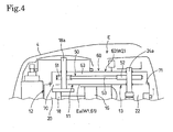
- Figs. 1 to 4 illustrate a vertical internal combustion engine E in an embodiment of the present invention.
- the vertical internal combustion engine E is incorporated into an outboard motor S.
- the outboard motor S includes the internal combustion engine E disposed with the center axis of its crankshaft 18 vertically extended, a mount case 1 supporting the internal combustion engine E, an extension case 2 joined to the lower end of the mount case 1, a gear case joined to the lower end of the extension case 2, an under cover 3 covering a part between a lower part of the internal combustion engine E and an upper part of the extension case 2, and an engine cover 4 joined to the upper end of the under cover 3.
- the outboard motor S has a transmission mechanism including a drive shaft 5 coaxially connected to a lower end part 18b of the crankshaft 18, a reversing mechanism held in the gear case, and a propeller.
- the power of the internal combustion engine E is transmitted from the crankshaft 18 through the drive shaft 5 and the reversing mechanism to the propeller.
- a mounting device for mounting the outboard motor S on the stern of a hull has a swivel shaft 6 fixed to the mount case 1 and the extension case 2, a swivel case 7 supporting the swivel shaft 6 for turning thereon, a tilting shaft 8 supporting the swivel case 7 so as to be turnable in a vertical plane, and a bracket 9 holding the tilting shaft 8 and attached to the stern of the hull.
- the mounting device holds the outboard motor S so as to be turnable on the tilting shaft 8 in a vertical plane relative to the hull and so as to be turnable on the swivel shaft 6 in a horizontal plane.
- the internal combustion engine E which is a multicylinder 4-stroke internal combustion engine, has an engine body including a cylinder block 11 provided with three cylinders 11n arranged in a row in a vertical direction, a crankcase 12 joined to the front end of the cylinder block 11, a cylinder head 13 joined to the rear end of the cylinder block 11, and a head cover 14 joined to the rear end of the cylinder head 13, and an oil pan 15 placed in the extension case 2 and joined to the lower end of the mount case 1.
- Pistons 16 are fitted in the cylinders 11n for reciprocation in the cylinders 11n, respectively.
- the pistons 16 are connected by connecting rods 17, respectively, to the crankshaft 18 placed in a crank chamber 20 defined by the cylinder block 11 and the crankcase 12.
- the vertical crankshaft 18 is supported for rotation in main bearings 19 on the cylinder block 11 and the crankcase 12 with its center axis extended substantially parallel to a vertical direction.
- the cylinder head 13 is provided with combustion chambers 21 respectively opposed to the pistons 16 with respect to a direction parallel to the axes of the cylinders 11n, intake ports respectively opening into the combustion chambers 21, exhaust ports respectively opening into the combustion chambers 21, and spark plugs respectively facing the combustion chambers 21.
- the cylinder head 13 is provided with intake valves for opening and closing the intake ports, and exhaust valves for opening and closing the exhaust ports.
- the intake valves and the exhaust valves are driven for opening and closing operations in synchronism with the rotation of the crankshaft 18 by an overhead camshaft type valve train 23 disposed in a valve train chamber 22 defined by the cylinder head 13 and the head cover 14.
- the valve train 23 includes a camshaft 24 provided with intake cams 25a and exhaust cams 25b, intake rocker arms 26a supported for rocking motions on a rocker arm shaft, and exhaust rocker arms 26b supported for rocking motions on a rocker arm shaft.
- the camshaft 24 is driven for rotation by the crankshaft 18 through a belt-drive transmission mechanism 50.
- the camshaft 24 has a center axis parallel to that of the vertical crankshaft 18.
- the intake valves and the exhaust valves are driven for opening and closing motions by the intake rocker arms 26a and the exhaust rocker arms 26b driven by the intake cams 25a and the exhaust cams 25b, respectively.
- the valve train 23 is a driven device provided with the camshaft 24, namely, a driven shaft, driven for rotation by the crankshaft 18.
- the internal combustion engine E has an intake system 27 including an inlet air silencer 27a, and an intake pipe 27b for carrying intake air taken in through the inlet air silencer 27a and metered by a throttle valve included in a carburetor 28 to the intake ports.
- the intake air that flows through an intake passage in the intake system 27 is mixed with fuel in a carburetor 28 for each cylinder 11n to produce an air-fuel mixture.
- the air-fuel mixture is sucked through the intake pipe 27b and the intake port into the combustion chamber 21. Then, the air-fuel mixture is ignited by the spark plug and burns to produce a combustion gas.
- the pistons 16 are reciprocated by the pressure of the combustion gas and drive the crankshaft 18 for rotation through the connecting rods 17.
- the combustion gas discharged as exhaust gas from the combustion chambers 21 flows through the exhaust ports into an exhaust manifold passage formed in the cylinder block 11. Then, the exhaust gas is discharged through passages formed in the mount case 1, the exhaust pipe and the extension case 2 into the water.
- the internal combustion engine E is provided with a lubrication system including the oil pan 15 placed below the cylinder block 11, the cylinder head 13 and the crankcase 12, an oil pump 29 (Fig. 1) driven by the camshaft 24 supported on the cylinder head 13, and oil passages.
- the oil pump 29 pumps up oil through a suction oil passage formed in the mount case 1, the cylinder block 11 and the cylinder head 13 from the oil pan 15.
- the oil discharged from the oil pump 29 flows through a discharge oil passage formed in the cylinder head 13 and the cylinder block 11 and an oil filter into a main oil gallery.
- the oil that has flowed into the main oil gallery is distributed through oil passages formed in the cylinder block 11, the cylinder head 13 and the crankshaft 18 to parts requiring lubrication including moving parts of the crankshaft 18 and the main bearings 19 in the crank chamber 20, and moving parts of the valve train 23 including the camshaft 24 and the rocker arms 26a and 26b in the valve train chamber 22.
- the used oil flows through return passages formed in the cylinder block 11, the cylinder head 13 and the mount case 1 and returns to the oil pan 15.
- the belt-drive transmission mechanism 50 is disposed in a belt chamber 63 defined by a transmission case 60 included in the internal combustion engine E.
- the transmission case 60 has a lower case 61, namely, a first case, joined to the upper end E a of the engine body, and an upper case 62, namely, a second case, joined to the lower case 61.
- the lower case 61 forms a bottom wall W1, namely, a first wall
- the upper case 62 forms a top wall W2, namely, a second wall.
- the bottom wall W1 and the top wall W2 defines the belt chamber 63.
- the lower case 61 is fastened to an upper end part 13a of the cylinder head 13 with bolts B1 and connected to the upper end part 13a by a camshaft holder 31.
- the upper end parts 11a, 12a and 13a form an upper end part E a of the engine body.
- the bottom wall W1 and the top wall W2 define the belt chamber 63.
- the belt-drive transmission mechanism 50 includes a drive pulley 51, a driven pulley 52, a belt 53 made of rubber, namely, an endless toothed belt, and a tension pulley 54 (Fig. 3).
- the drive pulley 51 is mounted in the belt chamber 63 on an upper end part 18a of the crankshaft 18 extended vertically upward through the lower case 61 and the upper case 62.
- the driven pulley 52 is mounted in the belt chamber 63 on an upper end part 24a of the camshaft 24 extended vertically upward through the lower case 61 and the upper case 62.
- the belt 53 is extended between the drive pulley 51 and the driven pulley 52 and is tensioned by the tension pulley 54.
- a part of the upper end part 18a projected upward from the upper case 62 is covered with a cover 32 attached to the upper case 61.
- An AC generator 34 is disposed in a space covered with the corer 32.
- the AC generator 34 includes a flywheel 33, permanent magnets 34a attached to the flywheel 33, an exciter coil 34b for ignition fixedly held on the upper end E a of the engine body, and a charging coil 34c.
- a ring gear 36 is attached to the circumference of the flywheel 33.
- a pinion 35a mounted on the drive shaft of a starting motor 35 is brought into mesh with the ring gear 36.
- a pulser rotor 37 is mounted on the upper end part 24a of the camshaft 24.
- a pulser coil 38 for generating a pulse signal indicating an angular position of the camshaft 24 is attached to the upper case 62.
- the upper case 62 is provided with openings through which the upper end parts 18a and 24a and the boss 52c of the driven pulley 52 are extended, and a hand hole 42 for adjusting the position of the tension pulley 54.
- the hand hole 42 is covered with a cover 39. Joints between the upper end parts 18a and 24a and the boss 52c and the openings are sealed in an oil-tight fashion.
- the lower case 61 disposed between the crank chamber 20 and the belt chamber 63 with respect to the vertical direction is provided with opening 41a and 41b through which the upper end parts 18a and 24a are passed, respectively, crank chamber vent holes 70 opening into the crank chamber 20, and valve train chamber vent holes 71 opening into the valve train chamber 22.
- the vent holes 70 open into a space 43 between the lower case 61 and the respective upper end parts 11a and 12a of the cylinder block 11 and the crankcase 12.
- the vent holes 70 communicate with the crank chamber 20 by way of a connecting passage 44 formed in the upper end 11a.
- a part of the lower case 61 around the opening 41a is joined to the cylinder block 11 and the crankcase 12 in an oil-tight fashion.
- a part of the lower case 61 around the opening 41b is joined to the cylinder head 13 and the camshaft holder 31 in an oil-tight fashion.
- the circular opening 41a is slightly greater than a circular flange 18c formed on the upper end part 18a of the crankshaft 18. Therefore, the flow of the gas between the crank chamber 20 and the belt chamber 63 through the opening 41a is very small and negligible as compared with the flow of the gas through the vent holes 70 and 71.
- the gas flows between the crank chamber 20 and the belt chamber 63 substantially only through the vent holes 70, and the gas flows between the valve train chamber 22 and the belt chamber 63 substantially only through the vent holes 71.
- the vent holes 70 and 71 lie below the belt 53.
- the belt chamber 53 is divided into an inside area surrounded by the belt 53 and an outside area extending outside the belt 53 in a horizontal plane.
- the vent holes 70 and 71 are formed in the outside area, namely, an area extending between the belt-drive transmission mechanism 50 and the flange 61a. Therefore, the vent holes 70 and 71 do not overlap the belt-drive transmission mechanism 50 in a horizontal plane.
- the lower case 61 serves as a shielding member or a partition wall entirely or substantially entirely isolating an overlying part of the belt-drive transmission mechanism 50 overlying the crank chamber 20 from the crank chamber 20 as viewed in a vertical direction or in a horizontal plane, and the vent holes 70 and 71 do not overlap the overlying part of the belt-drive transmission mechanism 50 corresponding to the crank chamber 20 as viewed in a horizontal plane.
- the overlying part of the belt-drive transmission mechanism 50 includes at least a part 53a (Fig. 1) of the belt 53 overlying the crank chamber 20 in a plane containing the belt 53 among the components of the belt-drive transmission mechanism 50.
- a breather structure for carrying blowby gases from the crank chamber 20 into the intake system 27 has a wall defining a breather chamber 45 in the valve train chamber 22, and a breather pipe 46 (Fig. 1) connecting the breather chamber 45 to the inlet air silencer 27a.
- the breather chamber 45 has an upstream part communicating with the valve train chamber 22, and a downstream part connected to the breather pipe 46. Blowby gases flow through the breather chamber 45 into the intake passage.
- the crank chamber 20 contains therein oil drips and oil mist produced from oil splashed by the rotating crankshaft 18 and oil discharged from the main bearings 19 , and blowby gases.
- An oil-containing gas namely, a mixture of blowby gases and oil mist, is drawn from the crank chamber 20 through internal breather passages, not shown, formed in the cylinder block 11 and the cylinder head 13 into the valve train chamber 22 by intake manifold vacuum created in the breather chamber 45 while the internal combustion engine E is running.
- part of the oil-containing gas flows from the crank chamber 20 through the connecting passage 44, the space 43 and the vent holes 70 into the belt chamber 63, and then flows from the belt chamber 63 through the vent holes 71 into the valve train chamber 22.
- Oil is separated from the oil-containing gas drawn into the valve train chamber 22 in the breather chamber 45 to produce a gas not containing oil.
- the gas not containing oil flows from the breather chamber 45 through the breather pipe 46 into the inlet air silencer 27a. Then, the gas is taken together with intake air into the combustion chambers 21.
- the oil mist contained in the oil-containing gas that flows from the crank chamber 20 into the belt chamber 63 wets the components of the transmission mechanism 50 including the belt 53 and the pulleys 51 and 52 within the belt chamber 63.
- the belt 53 and the pulleys 51 and 52 are lubricated.
- Oil drops scattered in the crank chamber 20 are blocked off by the lower case 61, so that the oil drops are restrained from adhering to the components of the transmission mechanism 50 including the belt 53.
- the belt chamber 63 is isolated from the crank chamber 20 in such a manner that the oil-containing gas from the crank chamber 20 is deviated from the transmission mechanism 50 including the belt 53, so that the transmission case 60 constitutes an isolating wall isolating the belt chamber 63 from the transmission case 60.
- the transmission case 60 forming the belt chamber 63 in the internal combustion engine E has the lower case 61 (or the bottom wall W1).
- the lower case 61 serves as a screening member for screening the belt chamber 63 from the crank chamber 20.
- the lower case 61 screens the part 53a (Fig. 1) of the belt 53 extending over the crank chamber 20 from the crank chamber 20.
- the lower case 61 screens the belt 53 from oil drops scattered out from the crank chamber 20 and oil-containing gas flowing out from the crank chamber 20.
- the belt 53 is prevented from being excessively wetted with oil drops and oil mist contained in the oil-containing gas and from being excessively exposed to blowby gases contained in the oil-containing gas.
- deterioration of the belt 53 due to contact with the oil and the blowby gases is suppressed, the life of the belt 53 lubricated by the oil in the oil-containing gas is extended and maintenance period can be shortened.
- the lower case 61 of the transmission case 60 serves as a screening member. Therefore, the internal combustion engine E does not need any special screening member, which reduces the number of component parts and the cost of the internal combustion engine E.
- the lower case 61 is provided with the vent holes 70 and 71 formed in the outside part W1b of the bottom wall W1 not overlapping the part 53a of the belt 53 extending over the crank chamber 20 in a horizontal plane. Therefore, the belt 53 is prevented from being excessively wetted with the oil contained in the oil-containing gas flowing through the vent holes 70 and 71 into the belt chamber 63, while lubrication of the belt 53 is ensured by the oil within the oil-containing gas flowing into the belt chamber through the vent holes 70 and 71.
- the lower case 61 (the bottom wall W1) is formed by the upper end part E a of the engine body, and the upper case 62 is joined to the upper end part E a to form the belt chamber 63. Since the upper end part E a serves also as the lower case 61, the number of component parts can be reduced, and the vertical dimension of the internal combustion engine can be reduced.
- the driven device may be an auxiliary device, such as a rotary oil pump 29 or other power transmission mechanism.
- a flywheel may be mounted on a lower end part 18b of the crankshaft 18 and the drive shaft 5 may be connected to the crankshaft 18 by the flywheel.
- the belt chamber 63 may be disposed inside the engine body or may be disposed under the engine body instead of being disposed above the engine body.
- the vertical internal combustion engine may be a single-cylinder internal combustion engine and may be incorporated into a machine other than the outboard motor.
Landscapes
- Engineering & Computer Science (AREA)
- Mechanical Engineering (AREA)
- General Engineering & Computer Science (AREA)
- Chemical & Material Sciences (AREA)
- Combustion & Propulsion (AREA)
- Ocean & Marine Engineering (AREA)
- Lubrication Of Internal Combustion Engines (AREA)
- Lubrication Details And Ventilation Of Internal Combustion Engines (AREA)
Applications Claiming Priority (1)
| Application Number | Priority Date | Filing Date | Title |
|---|---|---|---|
| JP2006156682A JP4583339B2 (ja) | 2006-06-05 | 2006-06-05 | ベルト式伝動機構を備えるバーチカル内燃機関 |
Publications (3)
| Publication Number | Publication Date |
|---|---|
| EP1865170A2 true EP1865170A2 (fr) | 2007-12-12 |
| EP1865170A3 EP1865170A3 (fr) | 2009-04-22 |
| EP1865170B1 EP1865170B1 (fr) | 2014-08-06 |
Family
ID=38481116
Family Applications (1)
| Application Number | Title | Priority Date | Filing Date |
|---|---|---|---|
| EP07252214.7A Not-in-force EP1865170B1 (fr) | 2006-06-05 | 2007-05-30 | Moteur à combustion interne verticale fourni avec un mécanisme de transmission d'entraînement par courroie |
Country Status (5)
| Country | Link |
|---|---|
| US (1) | US7704174B2 (fr) |
| EP (1) | EP1865170B1 (fr) |
| JP (1) | JP4583339B2 (fr) |
| CN (1) | CN101086229B (fr) |
| TW (1) | TWI319042B (fr) |
Families Citing this family (11)
| Publication number | Priority date | Publication date | Assignee | Title |
|---|---|---|---|---|
| JP4890322B2 (ja) * | 2007-03-30 | 2012-03-07 | 本田技研工業株式会社 | バーチカル型エンジンのブリーザ装置 |
| FR2990470B1 (fr) * | 2012-05-14 | 2014-05-16 | Peugeot Citroen Automobiles Sa | Carter de vilebrequin avec une poulie disposee a l'exterieur et a distance du carter en etant portee par un palier prevu sur le carter |
| KR101490924B1 (ko) * | 2013-06-27 | 2015-02-06 | 현대자동차 주식회사 | 자동차의 타이밍벨트 시스템 |
| US9303602B2 (en) * | 2013-09-27 | 2016-04-05 | Suzuki Motor Corporation | Intake apparatus of engine for outboard motor |
| WO2017135921A1 (fr) | 2016-02-01 | 2017-08-10 | Cummins Inc. | Consoles de support d'accessoire ayant des passages de flux d'air |
| JP6315157B1 (ja) * | 2016-10-03 | 2018-04-25 | 新日鐵住金株式会社 | トーションビーム用電縫鋼管 |
| JP6548308B2 (ja) * | 2017-01-26 | 2019-07-24 | 株式会社石川エナジーリサーチ | 対向ピストン型エンジン |
| US10054213B1 (en) * | 2018-04-09 | 2018-08-21 | Borgwarner Inc. | Vehicle drivetrain component having an internal vent relocation tube for venting a housing of the vehicle drivetrain component |
| JP7119904B2 (ja) * | 2018-10-29 | 2022-08-17 | トヨタ自動車株式会社 | オイル供給機構の制御装置 |
| US11953150B2 (en) * | 2022-07-29 | 2024-04-09 | Deere & Company | Belt trap apparatuses |
| US11906108B1 (en) * | 2022-07-29 | 2024-02-20 | Deere & Company | Belt trap with integrated tensioner |
Citations (1)
| Publication number | Priority date | Publication date | Assignee | Title |
|---|---|---|---|---|
| EP1482132A1 (fr) | 2003-05-26 | 2004-12-01 | HONDA MOTOR CO., Ltd. | Moteur à combustion interne vertical |
Family Cites Families (11)
| Publication number | Priority date | Publication date | Assignee | Title |
|---|---|---|---|---|
| JP2511068Y2 (ja) * | 1988-06-14 | 1996-09-18 | 本田技研工業株式会社 | 内燃機関のオイルポンプ駆動装置 |
| JPH02275020A (ja) * | 1989-04-13 | 1990-11-09 | Honda Motor Co Ltd | バーチカルクランク軸エンジン |
| JPH0475120U (fr) * | 1990-11-07 | 1992-06-30 | ||
| JP3331763B2 (ja) * | 1994-09-20 | 2002-10-07 | 日産自動車株式会社 | 内燃機関のブローバイガス換気装置 |
| US5722360A (en) * | 1994-09-28 | 1998-03-03 | Honda Giken Kogyo Kabushiki Kaisha | Engine assembly |
| JP3161956B2 (ja) * | 1995-12-04 | 2001-04-25 | 本田技研工業株式会社 | Ohcエンジンの潤滑システム |
| JP4052528B2 (ja) * | 1998-01-19 | 2008-02-27 | 本田技研工業株式会社 | 船外機 |
| JP2001123847A (ja) * | 1999-10-29 | 2001-05-08 | Sanshin Ind Co Ltd | 小型船舶用4サイクルエンジン |
| JP4371563B2 (ja) * | 2000-10-30 | 2009-11-25 | 本田技研工業株式会社 | エンジンの動弁機構 |
| JP4252844B2 (ja) * | 2003-05-26 | 2009-04-08 | 本田技研工業株式会社 | バーチカルエンジン |
| JP2004346896A (ja) * | 2003-05-26 | 2004-12-09 | Honda Motor Co Ltd | バーチカルエンジン |
-
2006
- 2006-06-05 JP JP2006156682A patent/JP4583339B2/ja not_active Expired - Fee Related
-
2007
- 2007-05-29 TW TW096119176A patent/TWI319042B/zh not_active IP Right Cessation
- 2007-05-30 EP EP07252214.7A patent/EP1865170B1/fr not_active Not-in-force
- 2007-06-01 US US11/809,875 patent/US7704174B2/en not_active Expired - Fee Related
- 2007-06-05 CN CN200710108544XA patent/CN101086229B/zh not_active Expired - Fee Related
Patent Citations (1)
| Publication number | Priority date | Publication date | Assignee | Title |
|---|---|---|---|---|
| EP1482132A1 (fr) | 2003-05-26 | 2004-12-01 | HONDA MOTOR CO., Ltd. | Moteur à combustion interne vertical |
Also Published As
| Publication number | Publication date |
|---|---|
| US20070251479A1 (en) | 2007-11-01 |
| JP2007321748A (ja) | 2007-12-13 |
| CN101086229A (zh) | 2007-12-12 |
| EP1865170B1 (fr) | 2014-08-06 |
| CN101086229B (zh) | 2010-08-04 |
| TWI319042B (en) | 2010-01-01 |
| JP4583339B2 (ja) | 2010-11-17 |
| TW200825272A (en) | 2008-06-16 |
| EP1865170A3 (fr) | 2009-04-22 |
| US7704174B2 (en) | 2010-04-27 |
Similar Documents
| Publication | Publication Date | Title |
|---|---|---|
| EP1865170B1 (fr) | Moteur à combustion interne verticale fourni avec un mécanisme de transmission d'entraînement par courroie | |
| US7647906B2 (en) | Vertical internal combustion engine provided with belt-drive transmission mechanism | |
| US6508238B2 (en) | Breather system for engine | |
| JP2001098950A (ja) | 船外機 | |
| CN102076933A (zh) | 内燃发动机油箱装置 | |
| JP3969549B2 (ja) | 船外機用エンジンの吸気通路構造 | |
| JP3942698B2 (ja) | 船外機用dohc型エンジンのブローバイガス還元装置 | |
| US7765969B2 (en) | Vertical internal combustion engine provided with belt-drive transmission mechanism | |
| JP2001107740A (ja) | 4サイクルエンジン | |
| JP4446616B2 (ja) | Ohcエンジンにおける潤滑構造 | |
| JP3971842B2 (ja) | 船外機 | |
| JP2001115851A (ja) | 船外機 | |
| JP2001082268A (ja) | V型4サイクルエンジンおよび船外機 | |
| JP2001082124A (ja) | 船外機 | |
| JP3222256B2 (ja) | エンジンのブローバイガス還元装置 | |
| JP3216087B2 (ja) | 船外機のブリーザ構造 | |
| JPH0547318U (ja) | 内燃機関におけるオイル注入口の構造 | |
| JP2001059409A (ja) | 内燃機関におけるカム軸シール部の潤滑装置 | |
| JPH04342811A (ja) | 船外機のエンジン潤滑構造 | |
| JPS61232331A (ja) | 2サイクル機関 | |
| JPH09249194A (ja) | 船外機用エンジンのタイミングプーリー取付構造 | |
| JPH1162538A (ja) | 船外機用dohc型エンジンの潤滑装置 | |
| JPH084518A (ja) | エンジンのブリーザ装置 | |
| JPH0151645B2 (fr) | ||
| JPS63138109A (ja) | V形エンジンの燃料噴射量制御装置 |
Legal Events
| Date | Code | Title | Description |
|---|---|---|---|
| PUAI | Public reference made under article 153(3) epc to a published international application that has entered the european phase |
Free format text: ORIGINAL CODE: 0009012 |
|
| 17P | Request for examination filed |
Effective date: 20070620 |
|
| AK | Designated contracting states |
Kind code of ref document: A2 Designated state(s): AT BE BG CH CY CZ DE DK EE ES FI FR GB GR HU IE IS IT LI LT LU LV MC MT NL PL PT RO SE SI SK TR |
|
| AX | Request for extension of the european patent |
Extension state: AL BA HR MK YU |
|
| PUAL | Search report despatched |
Free format text: ORIGINAL CODE: 0009013 |
|
| AK | Designated contracting states |
Kind code of ref document: A3 Designated state(s): AT BE BG CH CY CZ DE DK EE ES FI FR GB GR HU IE IS IT LI LT LU LV MC MT NL PL PT RO SE SI SK TR |
|
| AX | Request for extension of the european patent |
Extension state: AL BA HR MK RS |
|
| RIC1 | Information provided on ipc code assigned before grant |
Ipc: F02B 75/00 20060101ALI20090317BHEP Ipc: F02B 67/06 20060101ALI20090317BHEP Ipc: F02B 61/04 20060101AFI20070922BHEP Ipc: F01M 9/10 20060101ALI20090317BHEP |
|
| 17Q | First examination report despatched |
Effective date: 20090728 |
|
| AKX | Designation fees paid | ||
| RBV | Designated contracting states (corrected) |
Designated state(s): DE FR SE |
|
| REG | Reference to a national code |
Ref country code: DE Ref legal event code: 8566 |
|
| GRAP | Despatch of communication of intention to grant a patent |
Free format text: ORIGINAL CODE: EPIDOSNIGR1 |
|
| INTG | Intention to grant announced |
Effective date: 20140513 |
|
| RIN1 | Information on inventor provided before grant (corrected) |
Inventor name: KUBOTA, YUTAKA HONDA R&D CO. LTD Inventor name: TAKADA, HIDEAKI HONDA R&D CO. LTD Inventor name: KOYAMA, KAZUTAKE HONDA R&D CO. LTD Inventor name: KURODA, TATSUYA HONDA R&D CO. LTD |
|
| GRAS | Grant fee paid |
Free format text: ORIGINAL CODE: EPIDOSNIGR3 |
|
| GRAA | (expected) grant |
Free format text: ORIGINAL CODE: 0009210 |
|
| AK | Designated contracting states |
Kind code of ref document: B1 Designated state(s): DE FR SE |
|
| RIN1 | Information on inventor provided before grant (corrected) |
Inventor name: KOYAMA, KAZUTAKE HONDA R&D CO. LTD Inventor name: TAKADA, HIDEAKI HONDA R&D CO. LTD Inventor name: KURODA, TATSUYA HONDA R&D CO. LTD Inventor name: KUBOTA, YUTAKA HONDA R&D CO. LTD |
|
| REG | Reference to a national code |
Ref country code: DE Ref legal event code: R096 Ref document number: 602007037962 Country of ref document: DE Effective date: 20140911 |
|
| REG | Reference to a national code |
Ref country code: SE Ref legal event code: TRGR |
|
| REG | Reference to a national code |
Ref country code: DE Ref legal event code: R097 Ref document number: 602007037962 Country of ref document: DE |
|
| PLBE | No opposition filed within time limit |
Free format text: ORIGINAL CODE: 0009261 |
|
| STAA | Information on the status of an ep patent application or granted ep patent |
Free format text: STATUS: NO OPPOSITION FILED WITHIN TIME LIMIT |
|
| 26N | No opposition filed |
Effective date: 20150507 |
|
| REG | Reference to a national code |
Ref country code: FR Ref legal event code: PLFP Year of fee payment: 10 |
|
| REG | Reference to a national code |
Ref country code: FR Ref legal event code: PLFP Year of fee payment: 11 |
|
| REG | Reference to a national code |
Ref country code: FR Ref legal event code: PLFP Year of fee payment: 12 |
|
| REG | Reference to a national code |
Ref country code: DE Ref legal event code: R084 Ref document number: 602007037962 Country of ref document: DE |
|
| PGFP | Annual fee paid to national office [announced via postgrant information from national office to epo] |
Ref country code: DE Payment date: 20200519 Year of fee payment: 14 Ref country code: FR Payment date: 20200414 Year of fee payment: 14 |
|
| PGFP | Annual fee paid to national office [announced via postgrant information from national office to epo] |
Ref country code: SE Payment date: 20200512 Year of fee payment: 14 |
|
| REG | Reference to a national code |
Ref country code: DE Ref legal event code: R082 Ref document number: 602007037962 Country of ref document: DE Representative=s name: HL KEMPNER PATENTANWALT, RECHTSANWALT, SOLICIT, DE |
|
| REG | Reference to a national code |
Ref country code: DE Ref legal event code: R119 Ref document number: 602007037962 Country of ref document: DE |
|
| REG | Reference to a national code |
Ref country code: SE Ref legal event code: EUG |
|
| PG25 | Lapsed in a contracting state [announced via postgrant information from national office to epo] |
Ref country code: SE Free format text: LAPSE BECAUSE OF NON-PAYMENT OF DUE FEES Effective date: 20210531 |
|
| PG25 | Lapsed in a contracting state [announced via postgrant information from national office to epo] |
Ref country code: DE Free format text: LAPSE BECAUSE OF NON-PAYMENT OF DUE FEES Effective date: 20211201 |
|
| PG25 | Lapsed in a contracting state [announced via postgrant information from national office to epo] |
Ref country code: FR Free format text: LAPSE BECAUSE OF NON-PAYMENT OF DUE FEES Effective date: 20210531 |