EP1865196B1 - Mécanisme de transmission de puissance entre démarreur et moteur - Google Patents
Mécanisme de transmission de puissance entre démarreur et moteur Download PDFInfo
- Publication number
- EP1865196B1 EP1865196B1 EP06712930.4A EP06712930A EP1865196B1 EP 1865196 B1 EP1865196 B1 EP 1865196B1 EP 06712930 A EP06712930 A EP 06712930A EP 1865196 B1 EP1865196 B1 EP 1865196B1
- Authority
- EP
- European Patent Office
- Prior art keywords
- engaging
- ratchet
- disengaging
- lever
- engine
- Prior art date
- Legal status (The legal status is an assumption and is not a legal conclusion. Google has not performed a legal analysis and makes no representation as to the accuracy of the status listed.)
- Expired - Lifetime
Links
Images


Classifications
-
- F—MECHANICAL ENGINEERING; LIGHTING; HEATING; WEAPONS; BLASTING
- F16—ENGINEERING ELEMENTS AND UNITS; GENERAL MEASURES FOR PRODUCING AND MAINTAINING EFFECTIVE FUNCTIONING OF MACHINES OR INSTALLATIONS; THERMAL INSULATION IN GENERAL
- F16D—COUPLINGS FOR TRANSMITTING ROTATION; CLUTCHES; BRAKES
- F16D41/00—Freewheels or freewheel clutches
- F16D41/12—Freewheels or freewheel clutches with hinged pawl co-operating with teeth, cogs, or the like
-
- F—MECHANICAL ENGINEERING; LIGHTING; HEATING; WEAPONS; BLASTING
- F02—COMBUSTION ENGINES; HOT-GAS OR COMBUSTION-PRODUCT ENGINE PLANTS
- F02N—STARTING OF COMBUSTION ENGINES; STARTING AIDS FOR SUCH ENGINES, NOT OTHERWISE PROVIDED FOR
- F02N15/00—Other power-operated starting apparatus; Component parts, details, or accessories, not provided for in, or of interest apart from groups F02N5/00 - F02N13/00
- F02N15/02—Gearing between starting-engines and started engines; Engagement or disengagement thereof
- F02N15/022—Gearing between starting-engines and started engines; Engagement or disengagement thereof the starter comprising an intermediate clutch
- F02N15/027—Gearing between starting-engines and started engines; Engagement or disengagement thereof the starter comprising an intermediate clutch of the pawl type
-
- F—MECHANICAL ENGINEERING; LIGHTING; HEATING; WEAPONS; BLASTING
- F02—COMBUSTION ENGINES; HOT-GAS OR COMBUSTION-PRODUCT ENGINE PLANTS
- F02N—STARTING OF COMBUSTION ENGINES; STARTING AIDS FOR SUCH ENGINES, NOT OTHERWISE PROVIDED FOR
- F02N3/00—Other muscle-operated starting apparatus
- F02N3/02—Other muscle-operated starting apparatus having pull-cords
-
- F—MECHANICAL ENGINEERING; LIGHTING; HEATING; WEAPONS; BLASTING
- F02—COMBUSTION ENGINES; HOT-GAS OR COMBUSTION-PRODUCT ENGINE PLANTS
- F02N—STARTING OF COMBUSTION ENGINES; STARTING AIDS FOR SUCH ENGINES, NOT OTHERWISE PROVIDED FOR
- F02N5/00—Starting apparatus having mechanical power storage
- F02N5/02—Starting apparatus having mechanical power storage of spring type
-
- Y—GENERAL TAGGING OF NEW TECHNOLOGICAL DEVELOPMENTS; GENERAL TAGGING OF CROSS-SECTIONAL TECHNOLOGIES SPANNING OVER SEVERAL SECTIONS OF THE IPC; TECHNICAL SUBJECTS COVERED BY FORMER USPC CROSS-REFERENCE ART COLLECTIONS [XRACs] AND DIGESTS
- Y10—TECHNICAL SUBJECTS COVERED BY FORMER USPC
- Y10T—TECHNICAL SUBJECTS COVERED BY FORMER US CLASSIFICATION
- Y10T74/00—Machine element or mechanism
- Y10T74/13—Machine starters
- Y10T74/138—Radial meshing
Definitions
- the present invention relates to a power transmission mechanism between an engine starting device and an engine which can instantaneously start the engine by releasing a spring force accumulated in a damping and accumulating portion so as to rotate a rotation driven portion.
- a manual starting device of an internal combustion engine generally rotates a rope reel by pulling a recoil rope and executes an engine start by transmitting the rotation of the rope reel to a crank shaft of the engine.
- this kind of engine starting device not only it is necessary to pull the recoil rope in a state of making a pulling speed of the recoil rope higher to some degree, but also a pulling length is long. Accordingly, it is often the case that a great aged person and a weak person can not easily start the engine.
- the engine starting device by which even the person having a small pulling force of the recoil rope can easily start the internal combustion engine has proposed, for example, by Japanese Utility Model Application Laid-Open No. 1-91075 (patent document 1), Japanese Patent Application Laid-Open No. 2001-65435 (patent document 2) and the like.
- a recoil drum around which a recoil rope is wound
- a first power spring energizing in a direction of winding the recoil rope around the recoil drum
- a first ratchet formed in the recoil drum
- a second ratchet engaging with a second ratchet pawl provided in a crank shaft of the engine at a time of rotating in the engine starting direction
- a second power spring coupled to the second ratchet and accumulating a spring force rotating the ratchet in the engine starting direction
- a first ratchet pawl provided in the second ratchet, engaging with the first ratchet, transmitting the rotation of the recoil drum to the second power spring via the second ratchet, and accumulating the spring force in the power spring
- a stopper member detachably engaging with the second ratchet and inhibiting the rotation of the second ratchet generated by the spring force of the
- the stopper member In order to start the engine by means of the starting apparatus, the stopper member is previously engaged with the second ratchet, a sufficient force is accumulated in the second power spring by pulling the recoil rope at a proper frequency so as to rotate the recoil drum, and the engagement between the stopper member and the second ratchet is detached at a time of starting the engine, thereby rotating the crank shaft by the spring force of the second power spring so as to start the engine.
- the spring force is accumulated in the second power spring, the power spring is only rotated, and any load from the engine is not applied. Accordingly, the small pulling force of the recoil rope is sufficient, even the weak person can easily execute the pulling operation of the recoil rope and it is possible to securely start the engine at a necessary time.
- the engine starting device in the patent document 2 mentioned above is provided with a power spring force accumulating mechanism, a manual rope reel accumulating a rotating force in the power spring force accumulating mechanism , a reset lever having a stopper inhibiting a rotation in an output side of the power spring force accumulating mechanism and holding the accumulated rotating force to a predetermined torque, and a transmission mechanism transmitting the accumulated rotating force to a crank shaft of an internal combustion engine at a time when the stopper is cancelled.
- the reset lever can be manually switched from a stop position to a free position, and can automatically start the engine on the basis of the same operation as the patent document 1 mentioned above.
- the stopper exists at the stop position in a steady state until the reset lever is set to the free position, thereby inhibiting the rotation in the output side of the power spring force accumulating mechanism.
- a sufficient accumulated force for starting the engine is stored in the power spring force accumulating mechanism by pulling the recoil rope at several times, and if the sufficient accumulated force is stored, the reset lever is automatically moved to the free position so as to start the engine at the same time. Therefore, even the weak person can easily operate the engine.
- patent documents 1 and 2 disclose the structure in which the force is accumulated in the power spring force accumulating mechanism by rotating the coil drum (the rope reel) on the basis of the pulling operation of the recoil rope.
- the structure for example, disclosed in Japanese Patent No. 2573340 (patent document 3) accumulates force by rotating a power spring barrel drum of the power spring force accumulating mechanism via a ratchet mechanism in one direction on the basis of an electric power of an accumulator battery, cancels an engagement of a ratchet wheel of a rotation driven portion with a starter ratchet pawl at a time when the sufficient accumulated force for starting the engine is stored, and starts the engine by releasing the accumulated force.
- each of the patent documents 1 to 3 is configured such that the engine is started via a centrifugal clutch mechanism engaging with the rotation driven portion by winding up the power spring in which one end is supported to the power spring barrel drum and the other end is supported to the rotation driven portion, on the basis of the driving of the rotation drive portion so as to accumulate force, thereafter operating the stopper and the starter ratchet pawl, canceling the lock of eth rotation driven portion at an optional timing, and rapidly rotating the rotation drive portion in the accumulated force releasing direction.
- an engaging and disengaging pawl portion of the centrifugal clutch mechanism engaging with the ratchet wheel of the rotation driven portion by the centrifugal force on the basis of the high speed rotation is automatically disengaged from the engaged state with the ratchet wheel of the rotation driven portion, and the rotation of the engine is maintained.
- the stopper, the starter ratchet pawl and the ratchet wheel of the rotation driven portion are returned to the engaged state on the basis of an elastic force of a torsion spring or the like, and a ratchet tooth of the ratchet wheel in the rotation driven portion is stopped.
- a power source for igniting the engine is turned off at a time when a desired work is finished, and the engine is stopped. At this time, since the timing when the engine is stopped is not fixed, the stop position of the engaging and disengaging pawl of the centrifugal clutch mechanism rotating together with the rotation of the engine is not set to a fixed position as is different from the ratchet wheel of the rotation driven portion.
- the stop position of the engaging and disengaging pawl portion of the centrifugal clutch mechanism exists, for example, at a position between the adjacent ratchet teeth of the ratchet wheel of the rotation driven portion, in a state in which the engaging and disengaging pawl portion runs on the peripheral surface of the ratchet tooth, or at a position between the engaging and disengaging pawl portion and a pivot portion of the pawl portion where the engaging and disengaging pawl portion runs on the ratchet tooth.
- the collision at this time is not generated between the engaged surfaces of the ratchet tooth and the engaging and disengaging pawl portion, but is generated between a tooth end of the ratchet tooth and a pawl end of the engaging and disengaging pawl portion.
- the tooth tip and the pawl tip are broken due to an impact at that time, the accumulated force for starting the engine can not be well transmitted to the engine side and the engine start can not be executed. Further, in the case where, with respect to the accumulated force of the force accumulating power spring, the engagement between the engaging and disengaging lever and the first ratchet is not firmly executed, the accumulated force is released by an unexpected external force, and there is a possibility that the engine start can not be executed at an optional timing.
- the present invention is made for solving the problem mentioned above, and an object of the present invention is to provide an engine starting device and a power transmission mechanism between an engine and a lever which can avoid a breakage due to a collision between a pawl tip of an engaging and disengaging pawl portion of a centrifugal clutch mechanism coupling a rotation driven portion and the engine at a time of starting the engine, and a tooth tip of a ratchet tooth of the rotation driven portion engaging with the engaging and disengaging pawl portion.
- a power transmission mechanism between an engine starting device and an engine in which a damping and force accumulating means is interposed in a power transmission system between a rotation drive portion and a rotation driven portion, a power of the drive portion is accumulated between the damping and force accumulating means and the rotation driven portion, the accumulated force is released by canceling a lock of the rotation driven portion at a desired time, and the engine is started via an automatic connecting and disconnecting means arranged between the rotation driven portion and the engine, wherein the damping and force accumulating means has a power spring barrel drum and a power spring having one end supported to the barrel drum, and the rotation driven portion supports the other end of the power spring and is provided with an engaging and disengaging lever engaging and disengaging in accordance with an external operation so as to lock a rotation in one direction of the rotation driven portion, a first ratchet portion having a plurality of ratchet teeth engaging with and disengaging from the engaging and disengaging lever,
- the engaging and disengaging pawl portion formed in the leading end portion of the lever-shaped engaging and disengaging member and the ratchet tooth of the second ratchet portion are engaged by a surface contact.
- the ratchet tooth of the first ratchet portion and the ratchet tooth of the second ratchet portion are arranged at a predetermined phase difference.
- the engaging and disengaging lever and the first ratchet portion are made of a metal material, and an engaging and disengaging surface of the ratchet tooth of the first ratchet portion with the engaging and disengaging lever has an angle of slope smaller than 90 degree between the engaging and disengaging surface and the peripheral surface of the ratchet main body.
- a surface hardness of the engaging and disengaging lever may be set lower than a surface hardness of the ratchet tooth of the first ratchet portion.
- the engaging and disengaging lever is obtained in accordance with a press molding of a sheet metal, is entirely formed in an L shape, and is bent at 90 degree in one end so as to form the engaging and disengaging pawl. More preferably, the lever-shaped engaging and disengaging member having the centrifugal clutch function is arranged in a point symmetrical manner with respect to a center of rotation of the crank shaft.
- the shape of the lever-shaped engaging and disengaging portion of the centrifugal clutch mechanism is formed by concaving a side surface facing to the ratchet tooth of the second ratchet portion in a direction away from the ratchet tooth from the pivot portion to the engaging and disengaging pawl portion in the tip end.
- the engagement surface of the engaging and disengaging pawl portion is changed to the posture looking into the engagement surface of the ratchet tooth in accordance with the rotation of the ratchet tooth, and the concave portion of the lever-shaped engaging and disengaging member thereafter strides over the ratchet.
- the engagement surfaces of the ratchet tooth and the engaging and disengaging pawl portion are brought into contact with each other.
- the engagement surface of the engaging and disengaging pawl portion securely faces to the engagement surface of the ratchet tooth just before the engagement. For this reason, a surface engagement is achieved, and a local collision between the pawl tip and the tooth tip is avoided, so that the pawl tip and the tooth tip are not broken. Since the engagement at this time is achieved by the surface engagement, an impact force at a time of engaging is not concentrated to one point, and it is possible to do away with the deformation of the engaging and disengaging pawl portion and the ratchet tooth.
- the power spring barrel drum is supported to a main shaft via a bearing type one-way clutch so as to only allow the rotation of the power spring in the force accumulating direction, or a ratchet mechanism is used.
- the bearing type one-way clutch and the ratchet mechanism mentioned above are basically provided for accumulating the force in the power spring accommodated in the inner portion of the power spring barrel drum.
- an engine starting device of a type excluding the bearing type one-way clutch and the ratchet mechanism directly transmitting the drive of the rotation drive portion to the rotation driven portion via the barrel drum and the power spring and automatically starting the engine at a time when the power is accumulated in the power spring over the maximum load of the engine.
- the engine can be started at a stroke, for example, in the case of starting the engine on the basis of the pulling operation of the recoil rope. For this reason, this engine starting device is favorite of those skilled in the art or the like.
- the present invention is configured such that in addition to the matter that it is possible to release the accumulated force of the power spring so as to start the engine by operating the engaging and disengaging lever from the external portion as mentioned above so as to detach the engagement between the first ratchet portion of the rotation driven portion and the engaging and disengaging lever, it is possible to directly transmit the accumulated force stored in the power spring to the rotation driven portion so as to start the engine.
- the configuration is made such that a third ratchet portion is formed in the power spring barrel drum, and the engagement between the second engaging and disengaging lever and the power spring barrel drum is detached by actuating the engaging and disengaging lever in accordance with the external operation approximately the same time of detaching the engagement with the first rotation ratchet portion.
- the power spring barrel drum is rotated while accumulating the force in the power spring on the basis of the drive of the rotation drive portion, and a part of the accumulated force of the power spring is released so as to slowly rotate the first ratchet portion of the rotation driven portion concurrently, wherever the engaging and disengaging pawl portion of the centrifugal clutch mechanism stops at a time of the preceding engine stop. Consequently, the ratchet tooth is brought into contact with the engaging end disengaging pawl portion of the centrifugal clutch mechanism on the small impact force at a time of the rotation so as to be engaged. Accordingly, when switching to this type, the pawl tip and the tooth tip are not broken.
- the stop position of the first ratchet portion of the rotation drive portion is not necessarily constant in addition to the stop position of the engaging and disengaging pawl portion as mentioned above. Accordingly, in the case where the engine is started by engaging the engaging and disengaging lever with the ratchet tooth of the first ratchet portion, and detaching the engaging and disengaging lever after accumulating a desired accumulated force in the force accumulating power spring, the first ratchet portion is slightly rotated in the accumulated force releasing direction via the power spring if the power spring barrel drum is rotated in the force accumulating direction.
- the stop position of the engaging and disengaging pawl portion in the engine side is not constant at a time of the engine stop.
- the engaging and disengaging lever and the first ratchet portion are made of the metal, and a hardness of the engaging and disengaging lever is made lower than a hardness of the first ratchet portion, the engaging and disengaging lever is worn due to a repeated use. However, the motion in the crank axial direction is controlled even if the engaging and disengaging lever is worn, so that the engagement with the first ratchet portion becomes further firm.
- lever-like engaging and disengaging member having the centrifugal clutch function is arranged in a point symmetrical manner with respect to the center of rotation of the crank shaft, a pair of the lever-like engaging and disengaging members are simultaneously engaged with two ratchet teeth of the rotation driven portion at the phase difference of 180 degree. Accordingly, it is possible to securely transmit the drive force to the engine.
- FIG. 1 is a vertical cross sectional layout view showing an assembly structure between an engine starting device in accordance with the present embodiment and a crank shaft of an engine
- FIG. 2 is a back elevational view in the case of viewing the engine from the engine starting device side.
- a fan 106 is fixedly provided in a crank shaft 105 of an engine (not shown), and a pivot portion 106a rotatably pivoting a lever-shaped engaging and disengaging member 107 corresponding to one constituting member of a centrifugal clutch mechanism mentioned below is integrally formed in a back face in an engine starting device side of the fan 106 while pinching the crank shaft 105 therebetween.
- a pair of the pivot portions 106a are arranged at a phase difference of 180 degree while pinching the crank shaft 105 therebetween as shown in FIG. 2 , and a shape thereof is formed in a fan shape as seen from the engine starting device side.
- the lever-shaped engaging and disengaging member 107 is rotatably pivoted to the pivot portions 106a.
- the lever-shaped engaging and disengaging member 107 is formed in such a shape that an engaging and disengaging pawl portion 107b bent perpendicularly rises up on one end of a lever-shaped engaging and disengaging portion main body 107a as seen from the side view.
- a screw insertion hole inserting a locking screw 106b screwed into the pivot portion 106a therethrough is formed in a center portion as seen from a plan view.
- the lever-shaped engaging and disengaging member 107 has a tail portion 107c extending at a desired angle to an opposite side to the engaging and disengaging pawl portion 107b from the screw insertion hole and having a narrow shaped leading end, as shown in FIG. 1 .
- a torsion spring is interposed between the lever-shaped engaging and disengaging member 107 and the fan 106, and an elastic force of the torsion spring energizes the engaging and disengaging pawl portion 107b so as to always press to the crank shaft side.
- FIG. 3 shows an example of a typical entire shape of the lever-shaped engaging and disengaging member 107 in an enlarged manner.
- a pivot portion 107d between the lever-shaped engaging and disengaging portion main body 107a and the tail portion 107c is formed in a ring shape in which the screw insertion hole is formed as mentioned above.
- One side surface of the lever-shaped engaging and disengaging portion main body 107a is formed as a concave surface 107e curved in an arch shape so as to be concaved to an inner side.
- FIG. 4 is an exploded perspective view of a half case body 101 of the engine starting device 100 and an actuating member arranged in an inner portion of the case body 101.
- a description will be given of a specific example of the engine starting device in the present embodiment with reference to FIGS. 1 and 4 .
- the engine starting device 100 in the present embodiment is assembled such that a center of rotation of the rotation driven portion M rotatably attached to the main shaft 103 faces to an axial center of the crank shaft 105 in the engine side.
- the constituting members of the engine starting device 100 are all accommodated in the half case body 101 in the opposite engine side, as shown in FIG. 4 .
- the half case body 101 is provided with a cylindrical boss portion 101a so as to protrude toward the crank shaft side.
- a base portion of the main shaft 103 is firmly attached to the cylindrical boss portion 101a, and the constituting members of the engine starting device 100 mentioned below are sequentially assembled in the main shaft 103 and are fixed by the locking screw 102.
- the engine starting device 100 is provided with a rotation drive portion D and the rotation driven portion M.
- the rotation drive portion D is provided with a recoiling power spring 110 fixing an outer hook end 110a to an inner surface of the half case body 101 in a contact manner, a power spring case 113 having a circular hole 112 outside fitted to the cylindrical boss portion 101a and formed in a center portion, and brought into contact with the inner surface of the half case body 101 together with the outer hook end 110a so as to be positioned and fixed while accommodating the recoiling power spring 110, a recoil rope 115 having a grip 114 in one end, and a recoiling reel 116 fixing the other end of the recoil rope 115 to a part on a winding peripheral surface so as to wind the recoil rope 115 therearound.
- the one rotation driven portion M is provided with a ratchet wheel 120 in which first and second ratchet portions 121 and 122 having different diameters are integrally arranged on the same axis, as shown in FIGS. 1 and 4 .
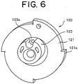
- a center portion of a back face in the rotation drive portion D side of the ratchet wheel 120 is provided, as shown in FIGS. 5 and 6 , with a circular protruding portion 123 in which a position deviated from the rotation center O of the ratchet wheel 120 is set to a center O', in a protruding manner, and a U-shaped notch groove 123a leaving for the center O' is formed in a part of a peripheral edge portion of the circular protruding portion 123.
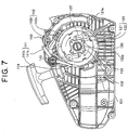
- a first engaging and disengaging lever 141 mentioned below of the present invention is engaged with and disengaged from a ratchet tooth 121a of the large-diameter first ratchet portion 121, as shown in FIGS. 7 and 10 , and the engaging and disengaging pawl portion 107b corresponding to the constituting member of the centrifugal clutch mechanism attached to the crank shaft 105 is engaged with and disengaged from a ratchet tooth 122a of the small-diameter second ratchet portion 122, as shown in FIG. 7 .
- the first ratchet portion 121 and the second ratchet portion 122 have four ratchet teeth 121a and 122a, and both the ratchet portions 121 and 122 have engagement surfaces in an opposite side to a direction allowing the rotation, for allowing only the rotation in the same direction. Since the small-diameter second ratchet portion 122 is engaged with the engaging and disengaging pawl portion 107b as shown in FIG.
- the small-diameter second ratchet portion 122 is set to a state in which it stops without rotating while following to a rotation in a force accumulating direction of a barrel drum 130 corresponding to a part of a damping and force accumulating means in the present invention, until the engine is started.
- the power spring barrel drum 130 corresponding to the damping and force accumulating means in the present embodiment and a force accumulating power spring 131 accommodated in the barrel drum 130 are interposed between the rotation drive portion D and the rotation driven portion M, as shown in FIGS. 1 , 4 and 12 .
- a plurality of protruding portions 130b protrude at a uniform interval from an inner peripheral surface of a power spring accommodating portion 130a of the barrel drum 130.
- the protruding portions 130b engage with an outer hook portion 131a of the force accumulating power spring 131 and are provided for winding the force accumulating power spring 131 in the force accumulating direction.
- a shape of the protruding portion 130b is structured, as shown in FIG. 12 , such that an engagement surfaces 130b-1 with which the outer hook portion 131a of the force accumulating power spring 131 is engaged is formed at a time of rotating in the force accumulating direction of the recoiling real 116, and a slope surface 130b-3 downward inclined smoothly toward an inner peripheral surface of the power spring accommodating portion 130a is formed from a top portion 130b-2 toward an opposite force accumulating direction.
- the inner hook portion 131b of the force accumulating power spring 131 is fitted and fixed to the U-shaped notch groove 123a formed in the circular protruding portion 123 of the ratchet wheel 120 of the rotation drivenportion M.
- An open surface in the driven portion side of the barrel drum 130 is closed by an annular cover 133, and controls a motion in an axial direction of the force accumulating power spring 131 accumulated in the inner portion.
- the protruding portion 130b constitutes a part of a torque limit mechanism. If the accumulated force of the force accumulating power spring 131 reaches a sufficient amount for starting the engine, it is impossible to maintain the engagement with the outer hook portion 131a any more. As a consequence, the engagement with the outer hook portion 131a is detached, the outer hook portion 131a gets over one after another, and it is impossible to accumulate the force any more in the force accumulating power spring 131. It is possible to inform the external portion of the matter that the accumulated force of the force accumulating power spring 131 reaches a limit on the basis of a sound generated at a time when the outer hook portion 131a gets over the protruding portion 130b.
- the torque limit mechanism is structured between the barrel drum 130 and the force accumulating power spring 131.
- the torque limit mechanism may be provided, for example, in the rotation driven portion M.
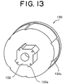
- a plurality of outer peripheral ratchet teeth 130c are integrally formed in an outer peripheral surface of the barrel drum 130 alternately at a pitch difference.
- the outer peripheral ratchet teeth 130c serves as a one-way rotating mechanism allowing the rotation in the force accumulating direction (a clockwise direction in FIG. 12 ) of the force accumulating power spring 131 accommodated in the inner portion as shown in FIGS. 12 and 13 , but inhibiting the inverse rotation.
- a ratchet mechanism is generally employed as the one-way rotating mechanism, it is possible to additionally employ various types of one-way rotating mechanisms, and an installed position is not necessarily limited to the outer peripheral surface of the barrel drum 130.
- the second engaging and disengaging lever 142 mentioned above is engaged with and disengaged from the outer peripheral ratchet tooth 130c.
- a small ratchet portion 132 is formed in a center portion of a back face facing to the recoiling reel 116 of the barrel drum 130 as shown in FIG. 13 .
- a facing portion to the small ratchet portion 132 of the recoiling reel 116 is provided, as shown in FIG. 4 , with an engaging and disengaging pawl lever 116a elastically engaging with and disengaging from a ratchet tooth 132a of the small ratchet portion 132, for rotating the barrel drum 130 only in the force accumulating direction.
- An engagement surface of the outer peripheral ratchet tooth 130c with the second engaging and disengaging lever 142 is directed toward the force accumulating direction of the force accumulating power spring 131.
- the engagement surface with the engaging and disengaging pawl lever 116a of the ratchet tooth 132a of the small ratchet portion 132 provided in the back face side of the barrel drum 130 is directed toward the opposite direction to the engagement surface with the ratchet tooth 121a of the first ratchet portion 121 in the ratchet wheel 120 of the rotation driven portion M.
- the ratchet tooth 132a of the small ratchet portion 132 is integrally formed in the barrel drum 130 at a phase difference of 90 degree.
- Two engaging and disengaging pawl levers 116a facing thereto are arranged in the peripheral edge portion in the barrel drum side of the recoiling reel 116 at a phase difference of 180 degree in a point symmetrical manner with respect to the center of rotation of the recoiling reel 116, in which one end is pivoted to a peripheral edge portion of the recoiling reel 116.
- the engaging and disengaging pawl lever 116a is always energized in a direction of engaging with the ratchet tooth 132a by a torsion spring (not shown).
- a pair of engaging and disengaging levers 116a are simultaneously engaged with two ratchet teeth 132a arranged at the phase difference of 180 degree among four ratchet teeth 132a, and the recoiling reel 116 and the barrel drum 130 are rotated in the force accumulating direction. However, only the recoiling reel 116 is rotatable in the opposite force accumulating direction.
- reference numeral 141 denotes the first engaging and disengaging lever engaging with and disengaging from the large-diameter first ratchet portion 121 of the ratchet wheel 120.
- Reference numeral 142 denotes the second engaging and disengaging lever engaging with and disengaging from the outer peripheral ratchet tooth 130c formed in the outer peripheral surface of the barrel drum 130.
- Reference numeral 143 denotes a slide switch corresponding to an operating means for executing the engagement and disengagement of the first engaging and disengaging lever 141.
- the first engaging and disengaging lever 141 and a linkpiece 143c mentioned below are made of a metal
- the second engaging and disengaging lever 142 is made of a plastic because the power spring barrel drum 130 is made of the plastic.
- Each of the first and second engaging and disengaging levers 141 and 142 is formed in the L shape, and the bent portions thereof are rotatably pivoted to the positions near the upper wall surface of the half case body 101 side by side, as shown in FIGS. 4 and 7 .
- the first engaging and disengaging lever portion 141 is constituted by an engaging pawl lever portion 141a engaging with and disengaging from the large-diameter first ratchet portion 121 of the ratchet wheel 120.
- An operation portion 141b rotationally operating the engaging pawl lever portion 141a around the bent portion.
- the engaging pawl lever portion 141a is energized in a direction of engaging with the large-diameter first ratchet portion 121 by a torsion spring 144.
- the second engaging and disengaging lever 142 is constituted by an engaging pawl lever portion 142a engaging with and disengaging from the outer peripheral ratchet tooth 130c formed in the outer peripheral surface of the power spring barrel drum 130 mentioned above, and an operation portion 142b rotatably operating the engaging pawl lever portion 142a around the bent portion.
- the engaging pawl lever portion 142a is energized in the direction of engaging with the outer peripheral ratchet tooth 130c of the barrel drum 130 by the torsion spring 145.
- the slide switch 143 is attached to the upper surface end portion of the half case body 101 so as tc be slidable in a horizontal direction in FIG. 7 .
- the structure of the slide switch 143 has an operation piece 143a in which a lot of concavo-convex surfaces are formed in an upper surface having an upper portion curved upward so as to bulge, and a slide piece 143b fitted and inserted to a slit (not shown) formed in the half case body 101 so as to protrude to a lower side form a lower surface of the operation piece 143a.
- the slide piece 143b and a leading end portion of the operation portion 141b of the first engaging and disengaging lever 141 are coupled by a link piece 143c.
- One end of the link piece 143c is attached to a leading end portion of the operation portion 141b of the first engaging and disengaging lever 141 so as to be relatively rotatable, and the other end of the link piece 130c is slidably attached to the slit formed in the slide piece 143b.
- first and second engaging and disengaging levers 141 and 142 are arranged such that in a state in which the first engaging and disengaging lever 141 is disengaged from the large-diameter first ratchet portion 121 of the ratchet wheel 120 via the link piece 143c, the leading end portion of the operation portion 141b of the first engaging and disengaging lever 141 pushes down the leading end portion of the operation portion 142b of the second engaging and disengaging lever 142 from the above, and the engaging pawl lever portion 142a of the second engaging and disengaging lever 142 is disengaged from the outer peripheral ratchet tooth 130c of the barrel drum 130.
- first and second engaging and disengaging levers 141 and 142 are removed constraint with the link piece 143c by sliding the slide switch 143 to a left side in FIG. 7 from an upward right side of the half case body 101, and are rotated in the directions respectively engaging with the first ratchet portion 121 of the ratchet wheel 120 and the outer peripheral ratchet tooth 130c of the barrel drum 130 on the basis of the elastic forces of the respective torsion springs 144 and 145.
- the first and second engaging and disengaging levers 141 and 142 are engaged with the outer peripheral ratchet tooth 130c of the power spring barrel drum 130 and the large-diameter first ratchet portion 121 of the ratchet wheel 120 on the basis of an application of the elastic force of the torsion springs 144 and 145.
- the power spring barrel drum 130 is rotated in the force accumulating direction.
- the second engaging and disengaging lever 142 and the outer peripheral ratchet tooth 130c are engaged, the rotation in the opposite direction is stopped.
- the ratchet wheel 120 of the rotation driven portion M is exposed to the force in the direction of releasing the spring force of the force accumulating power spring 131.
- the rotation is absolutely stopped. Accordingly, when rotating the recoiling reel 116 by pulling the recoil rope 115, the barrel drum 130 is rotated and only the force accumulation of the force accumulating power spring 131 is executed with respect to the ratchet wheel 120.
- the engine can be instantaneously started by canceling the engagement between the first and second engaging and disengaging levers 141 and 142 so as to switch to the first start mode, after pulling the recoil rope 115 at several times and storing the sufficient spring force to start the engine in the force accumulating power spring 131. It is possible to securely know on the basis of an informing signal generated by an operation of the torque limit mechanism mentioned above whether or not the accumulated force stored at this time reaches the sufficient force to start the engine.
- a manual operating machine mounting the engine having the above configuration thereon turns off an ignition switch without any delay and stops the engine drive after the end or the work.
- a stop position of the crank shaft 105 is not fixed, but is changed in a range of 360 degree, and stop positions of a pair of two lever-shaped engaging and disengaging members 107 of the centrifugal clutch mechanism attached to the fan 106 are, of course, changed.
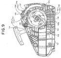
- a stop position of the ratchet tooth 122a of the second ratchet portion 122 which is rotationally stopped always exists at a fixed position. Accordingly, when the engine stops, the lever-shaped engaging and disengaging member 107 of the centrifugal clutchmechanismhaving the changed stop position is stopped at various positions, for example, as shown in FIGS. 7 to 10 .
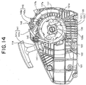
- FIGS. 14 to 16 show examples of three kinds of stop positions of the lever-shaped engaging and disengaging member 117 having a normal shape employed in the centrifugal clutch mechanism attached to the crank shaft 105 at a time of the engine stop.
- FIG. 14 in the case where the engaging and disengaging pawl portion 117b of the lever-shaped engaging and disengaging member 117 stops in a state of being brought into contact with the ratchet tooth 122a of the second ratchet portion 122, any particular problem is not generated.
- the shape of the lever-shaped engaging and disengaging portion main body 117a of the lever-shaped engaging and disengaging member 117 is formed only as a simple strip-shaped plate piece, as shown in these drawings.
- the engaging and disengaging pawl portion 117b of the lever-shaped engaging and disengaging member 117 stops in the state of running on the top position of the ratchet tooth 122a of the second ratchet portion 122. For this reason, an inner side surface of the lever-shaped engaging and disengaging portion main body 117 is pushed up on the basis of the rotation in the clockwise direction of the ratchet wheel 120, the lever-shaped engaging and disengaging member 117 is rotated in the clockwise direction around the center pivot portion, and the engaging and disengaging pawl portion 117b rises up toward the direction away from the ratchet tooth 122a.
- the engagement surface of the engaging and disengaging pawl portion 117b with the ratchet tooth 122a does not face to the engagement surface of the ratchet tooth 122a' in the next order, but is directed to the other direction.
- the second ratchet portion 122 is rapidly rotated, and when the ratchet tooth 122a' in the next order rapidly comes close, and the ratchet tooth 122a in the previous order passes through the inner side surface corresponding to the center pivot portion of the lever-shaped engaging and disengaging member 117, the engaging and disengaging pawl portion 117b of the lever-shaped engaging and disengaging member 117 moves so as to bow down toward the engagement surface of the ratchet tooth 122a' in the next order on the basis of the energization of the torsion spring (not shown).
- FIGS. 7 to 9 show a state in which the engagement surface of the engaging and disengaging pawl portion 107b of the lever-shaped engaging and disengaging member 107 faces to the engagement surface of the ratchet tooth 122a of the second ratchet portion 122, and the lever-shaped engaging and disengaging member 107 stops. As shown in this FIG.
- the side surface shape in the ratchet wheel 120 side of the lever-shaped engaging and disengaging portion main body 107a is formed in the concave surface curved and concaved in the direction away from the ratchet wheel 120 from the center engaging portion over the engaging and disengaging pawl portion 107b.
- the engagement surface of the engaging and disengaging pawl portion 107b faces to the engagement surface of the ratchet tooth 122a' in the next order in the same manner as the state shown in FIG. 9 , at a time when the engaging and disengaging pawl portion 107b gets over the ratchet tooth 122a in the previous order on the basis of the rotation of the second ratchet portion 122, whereby the engaging and disengaging pawl portion 107b and the ratchet tooth 122a' in the next order are securely surface engaged.
- the teeth of the first ratchet portion and the second ratchet portion are arranged so as to have alternate phase differences.
- a slight rotation of the rotation driven portion until the engagement between the first ratchet portion and the engaging and disengaging lever at a time of rotating the rotation drive portion during the force accumulation increases a possibility that the engagement between the engaging and disengaging pawl portion of the engine side automatic connecting and disconnecting means and the second ratchet portion forms the firm surface engagement.
- the accumulated force is maintained under the state in which the distance between the engaging and disengaging lever portion and the second ratchet portion is short. As a consequence, they are firmly surface engaged at a time of releasing the accumulated force, and it is possible to securely transmit the drive force on the basis of the accumulated force to the engine.
- the skilled worker avoids starting the engine after previously executing the force accumulating operation of the force accumulating power spring 131 as mentioned above.
- the first and second engaging and disengaging levers 141 and 142 are respectively disconnected from the ratchet wheel 120 and the power spring barrel drum 130.
- the barrel drum 130 is rotated by pulling the recoil rope 115 so as to rotate the recoiling reel 116.
- the rotation of the ratchet wheel 120 stops on the basis of the engagement of the centrifugal clutch mechanism attached to the crank shaft 105 of the engine via the fan 106 with the lever-shaped engaging and disengaging member 107. If the sufficient spring force to get over the maximum load of the engine is accumulated in the force accumulating power spring 131, the ratchet wheel 120 is automatically rotated in the direction of releasing the accumulated force, and the crank shaft 105 of the engine is rotated via the centrifugal clutch mechanism so as to start the engine.
- the ratchet wheel 120 and the barrel drum 130 starts backward rotating because the ratchet wheel 120 and the barrel drum 130 are not engaged with the first and second engaging and disengaging levers 141 and 142. Accordingly, the spring force of the force accumulating power sprig 131 accumulated till then is automatically released. As a result, even if the person stops the pulling operation of the recoil rope 115 in the middle and loses hold of the recoil rope 115, the accumulated force in the damping and force accumulating means is naturally released, and there is no risk that the engine is unexpectedly started.
- the ratchet tooth of this kind of ratchet wheel is formed as a flat right angled triangular shape having an engagement surface rising up to an outer side in a diametrical direction from the wheel main body.
- a surface hardness has been conventionally increased so as to avoid the abrasion by applying a surface treatment such as a nitriding process or the like to the ratchet tooth 121a and the ratchet pawl portion, particularly to the engaging and disengaging surfaces thereof.
- a surface treatment such as a nitriding process or the like
- the engaging and disengaging surface of the ratchet tooth 121a of the first ratchet portion 121 is risen up toward the outer side at a predetermined angle ⁇ of slope from the diametrical direction to the engaging and disengaging side.
- a notch portion 121b having a desired length is formed in a corner portion formed between the rising base end portion of the ratchet tooth 121a and the wheel main body toward the wheel center side.
- the engaging and disengaging surface of the ratchet tooth 121a is risen up while being inclined at the predetermined angle ⁇ of slope from the diametrical direction toward the engaging and disengaging side.
- the opposing pawl portion is securely gripped and locked at a time of engaging so as to be prevented from being easily disengaged, on the basis of the angle ⁇ of slope in the base portion side of the engaging and disengaging surface, even if the tooth top portion is worn.
- the notch portion 121b is formed in the corner portion formed between the rising base end portion of the ratchet tooth 121a and the wheel main body. For this reason, the impact force applied to the corner portion is dispersed via the notch portion 121b, the crank or the like is not generated, and the durability is increased.
- the engaging pawl 141a' is formed by bending the leading end portion of the engaging pawl lever portion 141a at right angle as shown in FIG. 20 , it is possible to make an engaging width in a crank axial direction of the engagement portion with the ratchet tooth 121a of the opposing first ratchet portion 121 larger on the basis of the bending length of the engaging pawl 141a'.
- first engaging and disengaging lever 141 and the first ratchet portion 121 are made of the metal, if the material of the first engaging and disengaging lever 141 is set such that the hardness is lower in comparison with the material of the first ratchet portion 121, the engaging and disengaging lever side is worn in accordance with a repeated use.
- the abrasion is formed to a shape by which the engagement with the first ratchet portion inhibits the movement in the crank axial direction. Therefore, the engagement becomes further firm.
- FIGS. 17 and 18 show a modified example of the U-shaped notch groove 123a of the circular protruding portion 123 formed in the back face side of the ratchet wheel 120.
- an approximately inverted-J-shaped notch groove 123b is formed by further notching one shoulder portion of the notch groove 123a.
- the inner hook portion 131b of the force accumulating power spring 131 wound in the clockwise direction as seen from the engine side shown in FIG. 7 is fitted and fixed to the notch groove 123b.
- the one should portion is not necessary. Accordingly, in the case of notching the one shoulder portion, the durability of the inner hook portion 131b of the force accumulating power force 131 is improved.
- the embodiment mentioned above is configured such that the first and second engaging and disengaging levers 141 and 142 are respectively engaged with and disengaged from the first ratchet portion 121 of the ratchet wheel 120 in the rotation driven portion M and the outer peripheral ratchet tooth 130c of the power spring barrel drum 130 in an interlocking manner.
- the power spring barrel drum 130 is attached to the main shaft 103 via the bearing type one-way clutch.
- FIG. 19 shows a second embodiment in accordance with the present invention.
- the ratchet tooth is not formed in the outer periphery of the power spring barrel drum 130, but a simple smooth peripheral surface is only provided thereon.
- the second engaging and disengaging lever 142 does not exist.
- the other structures are not substantially changed from the embodiment mentioned above. Accordingly, substantially the same aspect as the aspect shown in FIG.
- the shape of the lever-shaped engaging and disengaging member 107 has the shape peculiar to the present invention as shown in FIG. 3 .
- the rotation driven portion M is provided with the ratchet wheel 120 having the large-diameter and small-diameter first and second ratchet portions 121 and 122, in the same manner as the first embodiment as mentioned above.
- the inner hook portion 131b of the force accumulating power spring 131 is fitted and fixed to the U-shaped notch groove 123a formed in the small-diameter circular protruding portion 123, and the first engaging and disengaging lever 141 is engaged with the large-diameter first ratchet portion 121. For this reason, the ratchet wheel 120 is under the stop state until the engagement is canceled.
- the power spring barrel drum 130 is rotated in the force accumulating direction by pulling the recoil rope 115 so as to rotate the recoiling reel 116, the sufficient spring force is stored in the force accumulating power spring 131, and the accumulated force reaches the sufficient force to start the engine.
- the rotating force is transmitted to the crank shaft 105 of the engine via the centrifugal clutchmechanism (not shown) via the ratchet wheel 120 of the rotation driven portion M, and the engine is automatically started.
- the engine can be instantaneously started by sliding the slide switch 143 mentioned above to the right side as shown in FIG.
- the shape of the lever-shaped engaging and disengaging portion main body 107a keeps the special shape of the present invention whatever position the engaging and disengaging pawl portion 107b of the lever-shaped engaging and disengaging member 107 in the engine side engaging with the second ratchet portion 122 exists as mentioned above, at this starting time.
- the recoiling reel 116 is rotated in the engine rotating direction on the basis of the pulling operation of the recoil rope 115 of the rotation drive portion D by sliding the slide switch 143 on the surface of the half case body 101.
- the desired spring force is accumulated in the force accumulating power spring 131 while rotating the power spring barrel drum 130 of the damping and force accumulating means in the same direction, the accumulated force is directly transmitted to the ratchet wheel 120 corresponding to the rotation driven portion M, and the accumulated force reaches the necessary and sufficient force to start the engine, it is possible to automatically start the engine.
- the slide switch 143 is slid in the inverse direction, it is possible to previously store the spring force necessary for starting the engine in the force accumulating power spring 131 by pulling the recoil rope 115 of the rotation drive portion D and rotating the power spring barrel drum 130 in the same direction. Under the state in which the accumulated force is held, it is possible to release the accumulated force stored in the force accumulating power spring 131 in the optional place at the desired time and it is possible to instantaneously start the engine on the moment.
- the material of the lever-shaped engaging and disengaging member 107 is set to the metal material.
Landscapes
- Engineering & Computer Science (AREA)
- General Engineering & Computer Science (AREA)
- Mechanical Engineering (AREA)
- Chemical & Material Sciences (AREA)
- Combustion & Propulsion (AREA)
- Transmission Devices (AREA)
- One-Way And Automatic Clutches, And Combinations Of Different Clutches (AREA)
Claims (6)
- Mécanisme de transmission de puissance entre un dispositif de démarrage de moteur (100) et un moteur dans lequel un moyen d'amortissement et d'accumulation de force (130, 131) est intercalé dans un système de transmission de puissance entre une partie d'entraînement de rotation (D) et une partie entraînée de rotation (M), une puissance de la partie d'entraînement est accumulée entre le moyen d'amortissement et d'accumulation de force (130) et la partie entraînée de rotation (M), la force accumulée est libérée en annulant un verrouillage de la partie entraînée de rotation (M) à un moment souhaité, et le moteur est démarré via un moyen de connexion et de déconnexion automatique (107) agencé entre la partie entraînée de rotation (M) et le moteur, caractérisé en ce que :le moyen d'amortissement et d'accumulation de force (130, 131) a un tambour de barillet de ressort-moteur (130) et un ressort-moteur (131) ayant une extrémité (131a) supportée sur le tambour de barillet (130), etla partie entraînée de rotation (M) supporte l'autre extrémité (131b) du ressort-moteur (131) et est prévue avec :un premier levier de mise en prise et de dégagement (141) se mettant en prise et se dégageant selon une opération externe d'un élément de commande externe (143) afin de verrouiller et de déverrouiller une rotation dans une direction de la partie entraînée de rotation (M),une première partie de rochet (121) ayant une pluralité de dents de rochet (121a) se mettant en prise avec et se dégageant du premier levier de mise en prise et de dégagement (141), etune seconde partie de rochet (122) ayant une pluralité de dents de rochet (122a) se mettant en prise avec et se dégageant du moyen de connexion et de déconnexion automatique (107), dans lequel la première partie de rochet (121) et la seconde partie de rochet (122) sont agencées de manière solidaire sur le même axe,le moyen de connexion et de déconnexion automatique (107) est supporté de manière pivotante sur un élément fonctionnant avec une rotation de moteur, tel qu'un ventilateur (106), un vilebrequin (105) ou similaire du moteur dans une partie fixée de manière pivotante, a une partie de cliquet de mise en prise et de dégagement (107b) dans une extrémité d'attaque, a un élément de mise en prise et de dégagement en forme de levier (107) alimenté dans une direction telle que la partie de cliquet de mise en prise et de dégagement (107b) se met en prise avec la seconde partie de rochet (122), et est prévu avec une fonction d'embrayage centrifuge qui, lorsque le vilebrequin (105) du moteur atteint une vitesse de rotation souhaitée, l'élément de mise en prise et de dégagement en forme de levier (107) tourne contre l'alimentation sur la base d'une force centrifuge, et la mise en prise entre la partie de cliquet de mise en prise et de dégagement (107b) et la dent de rochet (122a) de la seconde partie de rochet (122) est automatiquement déconnectée, etune surface latérale dans un côté faisant face à la dent de rochet (122a) de la seconde partie de rochet (122) de l'élément de mise en prise et de dégagement en forme de levier (107) a une forme concave (107e) dans une direction à distance de la dent de rochet (122a) de la seconde partie de rochet (122), dans lequel la force concave s'étend à partir de la partie fixée de manière pivotante jusqu'à la partie de cliquet de mise en prise et de dégagement (107b),dans lequel la dent de rochet (121a) de la première partie de rochet (121) et la dent de rochet (122a) de la seconde partie de rochet (122) sont agencées à une différence de phase prédéterminée.
- Mécanisme de transmission de puissance selon la revendication 1, dans lequel la partie de cliquet de mise en prise et de dégagement (107b) formée dans la partie d'extrémité d'attaque de l'élément de mise en prise et de dégagement en forme de levier (107) et la dent de rochet (122a) de la seconde partie de rochet (122) sont mises en prise par un contact de surface.
- Mécanisme de transmission de puissance selon la revendication 1, dans lequel le premier levier de mise en prise et de dégagement (141) et la première partie de rochet (121) sont réalisés à partir d'un matériau métallique, et une surface de mise en prise et de dégagement de la dent de rochet (121a) de la première partie de rochet (121) avec le premier levier de mise en prise et de dégagement (141) a un angle d'inclinaison inférieur à 90 degrés entre la surface de mise en prise et de dégagement et la surface périphérique du corps principal de rochet (120).
- Mécanisme de transmission de puissance selon la revendication 3, dans lequel une dureté de surface du premier levier de mise en prise et de dégagement (141) est ajustée de manière à être inférieure à une dureté de surface de la dent de rochet (121a) de la première partie de rochet (121).
- Mécanisme de transmission de puissance selon la revendication 3 ou 4, dans lequel le premier levier de mise en prise et de dégagement (141) est obtenu selon un moulage à la presse d'un métal en feuille, est entièrement formé selon une forme de L et est plié à 90 degrés dans une extrémité afin de former le cliquet de mise en prise et de dégagement (141a).
- Mécanisme de transmission de puissance selon l'une quelconque des revendications 1 à 4, dans lequel l'élément de mise en prise et de dégagement en forme de levier (107) ayant une fonction d'embrayage centrifuge est agencé d'une manière symétrique ponctuelle par rapport à un centre de rotation du vilebrequin (105).
Applications Claiming Priority (2)
| Application Number | Priority Date | Filing Date | Title |
|---|---|---|---|
| JP2005031341A JP4376193B2 (ja) | 2005-02-08 | 2005-02-08 | エンジン始動装置とエンジンとの間の動力伝達機構 |
| PCT/JP2006/301787 WO2006085473A1 (fr) | 2005-02-08 | 2006-02-02 | Mécanisme de transmission de puissance entre démarreur et moteur |
Publications (3)
| Publication Number | Publication Date |
|---|---|
| EP1865196A1 EP1865196A1 (fr) | 2007-12-12 |
| EP1865196A4 EP1865196A4 (fr) | 2011-01-05 |
| EP1865196B1 true EP1865196B1 (fr) | 2018-04-18 |
Family
ID=36793048
Family Applications (1)
| Application Number | Title | Priority Date | Filing Date |
|---|---|---|---|
| EP06712930.4A Expired - Lifetime EP1865196B1 (fr) | 2005-02-08 | 2006-02-02 | Mécanisme de transmission de puissance entre démarreur et moteur |
Country Status (7)
| Country | Link |
|---|---|
| US (1) | US7819105B2 (fr) |
| EP (1) | EP1865196B1 (fr) |
| JP (1) | JP4376193B2 (fr) |
| CN (1) | CN101128668B (fr) |
| ES (1) | ES2673504T3 (fr) |
| SE (1) | SE529695C2 (fr) |
| WO (1) | WO2006085473A1 (fr) |
Families Citing this family (12)
| Publication number | Priority date | Publication date | Assignee | Title |
|---|---|---|---|---|
| USD595738S1 (en) | 2007-06-29 | 2009-07-07 | Husqvarna Zenoah Co., Ltd. | Rotor for an internal combustion engine |
| JP2009293485A (ja) * | 2008-06-04 | 2009-12-17 | Honda Motor Co Ltd | 蓄力式リコイルスタータ |
| US7886709B2 (en) * | 2009-05-29 | 2011-02-15 | GM Global Technology Operations LLC | Spring start for a vehicle engine |
| JP2013510974A (ja) * | 2009-11-13 | 2013-03-28 | ディーティーアイ グループ ビー.ブイ. | 車両のエンジン用の始動システム |
| JP5836713B2 (ja) * | 2010-12-01 | 2015-12-24 | スターテング工業株式会社 | リコイルスタータ |
| DE202011000610U1 (de) * | 2011-03-17 | 2012-06-18 | Makita Corporation | Startvorrichtung für mindestens eine Verbrennungskraftmaschine, insbesondere Seilzugstartvorrichtung |
| TWI413729B (zh) * | 2011-08-26 | 2013-11-01 | Sanyang Industry Co Ltd | Engine flameout restart signal generation mechanism |
| CN105736207A (zh) * | 2016-03-18 | 2016-07-06 | 山东华盛农业药械有限责任公司 | 易起动器 |
| CN106090068B (zh) * | 2016-08-17 | 2018-05-18 | 广东工业大学 | 一种超越离合器 |
| EP3744968B1 (fr) | 2019-05-28 | 2025-07-02 | Andreas Stihl AG & Co. KG | Boîtier de ressort et dispositif de lancement doté d'un tel boîtier de ressort |
| CN113515816B (zh) * | 2020-12-30 | 2023-07-21 | 中国航发沈阳发动机研究所 | 一种棘轮离合器脱开转速确定方法 |
| CN116713259A (zh) * | 2023-04-24 | 2023-09-08 | 浙江宝业建设集团有限公司 | 一种建筑垃圾环保清理设备及清理方法 |
Family Cites Families (43)
| Publication number | Priority date | Publication date | Assignee | Title |
|---|---|---|---|---|
| US3010443A (en) * | 1959-03-19 | 1961-11-28 | Garland E Lyvers | Engine starting device |
| JPS3825704Y1 (fr) * | 1961-09-07 | 1963-11-28 | ||
| US3861374A (en) * | 1971-05-05 | 1975-01-21 | Mccullock Corp | Lightweight chain saw with engine restarting system and method and apparatus for restarting a warm internal combustion engine |
| US4104927A (en) * | 1976-11-29 | 1978-08-08 | Jensen Jorn Benned | Engine starter |
| FR2475663A1 (fr) * | 1980-02-12 | 1981-08-14 | Renault | Dispositif de blocage en position d'arret pour vehicule automobile |
| JPS5851271A (ja) * | 1981-09-19 | 1983-03-25 | Mitsubishi Heavy Ind Ltd | 内燃機関の蓄力式自動始動装置 |
| US4480605A (en) * | 1983-05-09 | 1984-11-06 | Brunswick Corporation | Recoil starter |
| US4582030A (en) * | 1984-03-02 | 1986-04-15 | Tecumseh Products Company | Mounting recoil starter |
| JPS6491075A (en) | 1987-10-02 | 1989-04-10 | Hitachi Ltd | Magnetic field distribution measuring apparatus |
| JP2579650B2 (ja) | 1987-11-27 | 1997-02-05 | オリンパス光学工業株式会社 | 体内用レーザ光照射装置 |
| JPH0191075U (fr) | 1987-12-08 | 1989-06-15 | ||
| JPH01190965A (ja) * | 1988-01-22 | 1989-08-01 | Mitsubishi Heavy Ind Ltd | 内燃機関の渦巻バネ式始動装置 |
| JPH01191075A (ja) | 1988-01-27 | 1989-08-01 | Nec Corp | 半導体エージング装置 |
| JP2573340B2 (ja) | 1988-11-24 | 1997-01-22 | 三菱重工業株式会社 | 汎用ガソリンエンジンの渦巻バネ式始動装置 |
| US5083534A (en) * | 1989-04-05 | 1992-01-28 | Mitsubishi Jukogyo Kabushiki Kaisha | Spiral spring type starter apparatus for an internal combustion engine |
| US4970998A (en) * | 1989-05-26 | 1990-11-20 | Eaton Indiana, Inc. | Offset starter pawl |
| JPH05223025A (ja) | 1992-02-10 | 1993-08-31 | Toyota Motor Corp | 燃料タンク内圧力制御装置 |
| JPH07174061A (ja) * | 1993-05-07 | 1995-07-11 | Nitsukari:Kk | 畜力式リコイルスタータ |
| JP3496394B2 (ja) * | 1996-05-08 | 2004-02-09 | トヨタ自動車株式会社 | 流体式トルクコンバータ |
| US6230678B1 (en) * | 1998-10-30 | 2001-05-15 | Briggs & Stratton Corporation | Starting and stopping device for internal combustion engine |
| US6615787B2 (en) * | 1998-10-30 | 2003-09-09 | Briggs & Stratton Corporation | Engine starting and stopping device |
| US6325036B1 (en) * | 1998-10-30 | 2001-12-04 | Briggs & Stratton Corporation | Starting and stopping device for an internal combustion engine |
| JP3274671B2 (ja) | 1999-08-25 | 2002-04-15 | 株式会社共立 | スタータ装置 |
| US6508220B1 (en) * | 1999-08-25 | 2003-01-21 | Kioritz Corporation | Starter |
| JP4017792B2 (ja) | 1999-08-25 | 2007-12-05 | 株式会社共立 | 蓄力式スタータ装置 |
| JP4581231B2 (ja) | 2000-11-27 | 2010-11-17 | 富士電機システムズ株式会社 | 電圧駆動型半導体素子のゲート駆動回路 |
| JP2002327666A (ja) * | 2001-03-01 | 2002-11-15 | Starting Ind Co Ltd | スタータ装置 |
| EP1253315B1 (fr) * | 2001-04-27 | 2007-03-21 | Maruyama MFG. Co., Inc. | Démarreurs pour moteurs à combustion interne |
| JP3820140B2 (ja) * | 2001-04-27 | 2006-09-13 | 株式会社丸山製作所 | 内燃機関始動装置 |
| JP4109838B2 (ja) * | 2001-05-25 | 2008-07-02 | スターテング工業株式会社 | リコイルスタータ装置 |
| JP4069971B2 (ja) | 2002-03-12 | 2008-04-02 | ハスクバーナ・ゼノア株式会社 | エンジンのリコイルスタータ |
| US6959680B2 (en) * | 2002-07-24 | 2005-11-01 | Starting Industrial Co., Ltd. | Recoil starter |
| JP2004068639A (ja) | 2002-08-02 | 2004-03-04 | Showa Kiki Kogyo Kk | ロック式蓄力スタータ装置 |
| JP3680052B2 (ja) | 2002-09-26 | 2005-08-10 | 株式会社クボタ | エンジンのリコイルスタータ |
| CN100523481C (zh) * | 2002-10-21 | 2009-08-05 | 开始工业株式会社 | 一种反冲起动器 |
| JP4346922B2 (ja) | 2002-10-21 | 2009-10-21 | スターテング工業株式会社 | リコイルスタータ |
| JP3878564B2 (ja) * | 2003-02-28 | 2007-02-07 | スターテング工業株式会社 | 蓄力式リコイルスタータ |
| US6901889B1 (en) * | 2004-03-10 | 2005-06-07 | Tgi, Inc. | Fumigation system for a diesel engine |
| JP2005337224A (ja) * | 2004-04-28 | 2005-12-08 | Komatsu Zenoah Co | エンジン始動装置 |
| US7191752B2 (en) * | 2004-05-14 | 2007-03-20 | Husqvarna Outdoor Products Inc. | Energy storing starter assembly |
| JP4271621B2 (ja) | 2004-06-11 | 2009-06-03 | ハスクバーナ・ゼノア株式会社 | エンジン始動装置 |
| CN101189427B (zh) * | 2005-12-20 | 2011-08-17 | 富世华智诺株式会社 | 发动机起动装置 |
| US7252065B1 (en) * | 2006-05-11 | 2007-08-07 | Husqvarna Outdoor Products Inc. | Energy storing starting device |
-
2005
- 2005-02-08 JP JP2005031341A patent/JP4376193B2/ja not_active Expired - Lifetime
-
2006
- 2006-02-02 CN CN2006800041024A patent/CN101128668B/zh not_active Expired - Fee Related
- 2006-02-02 WO PCT/JP2006/301787 patent/WO2006085473A1/fr not_active Ceased
- 2006-02-02 US US11/883,664 patent/US7819105B2/en active Active
- 2006-02-02 ES ES06712930.4T patent/ES2673504T3/es not_active Expired - Lifetime
- 2006-02-02 EP EP06712930.4A patent/EP1865196B1/fr not_active Expired - Lifetime
- 2006-09-27 SE SE0602011A patent/SE529695C2/sv not_active IP Right Cessation
Also Published As
| Publication number | Publication date |
|---|---|
| JP4376193B2 (ja) | 2009-12-02 |
| CN101128668A (zh) | 2008-02-20 |
| US20080115756A1 (en) | 2008-05-22 |
| SE529695C2 (sv) | 2007-10-30 |
| ES2673504T3 (es) | 2018-06-22 |
| EP1865196A1 (fr) | 2007-12-12 |
| CN101128668B (zh) | 2013-01-02 |
| EP1865196A4 (fr) | 2011-01-05 |
| WO2006085473A1 (fr) | 2006-08-17 |
| US7819105B2 (en) | 2010-10-26 |
| JP2006219993A (ja) | 2006-08-24 |
| SE0602011L (sv) | 2006-11-28 |
Similar Documents
| Publication | Publication Date | Title |
|---|---|---|
| EP1865196B1 (fr) | Mécanisme de transmission de puissance entre démarreur et moteur | |
| US4019490A (en) | Pull-rope recoil starter | |
| US6679217B2 (en) | Starter | |
| JP4064961B2 (ja) | リコイルスタータ | |
| US20090255502A1 (en) | Starter System for Engine | |
| EP1394404A2 (fr) | Démarreur à tirette à câble | |
| US6901899B2 (en) | Recoil starter | |
| JP2004360494A (ja) | リコイルスタータ | |
| US6679216B2 (en) | Starters for internal combustion engine | |
| EP2218907B1 (fr) | Lanceur à rappel | |
| JP5428093B2 (ja) | 小型エンジンの始動装置 | |
| JP4444871B2 (ja) | エンジン始動装置 | |
| JP4009137B2 (ja) | リコイルスタータ | |
| JP4098537B2 (ja) | リコイルスタータ | |
| JP4578304B2 (ja) | エンジン始動装置 | |
| JP3914846B2 (ja) | リコイルスタータ | |
| EP3317561B1 (fr) | Tendeur bimode | |
| JP2003336567A (ja) | リコイルスタータ | |
| JP2003172233A (ja) | 内燃機関始動用のリコイルスタータ | |
| JP2002138930A (ja) | リコイルスタータ装置 | |
| JP2004308444A (ja) | スタータ装置 |
Legal Events
| Date | Code | Title | Description |
|---|---|---|---|
| PUAI | Public reference made under article 153(3) epc to a published international application that has entered the european phase |
Free format text: ORIGINAL CODE: 0009012 |
|
| 17P | Request for examination filed |
Effective date: 20070810 |
|
| AK | Designated contracting states |
Kind code of ref document: A1 Designated state(s): DE ES FR GB IT |
|
| RAP1 | Party data changed (applicant data changed or rights of an application transferred) |
Owner name: ZENOAH CO., LTD. Owner name: STARTING INDUSTRIAL CO., LTD. |
|
| RBV | Designated contracting states (corrected) |
Designated state(s): DE ES FR GB IT |
|
| RAP1 | Party data changed (applicant data changed or rights of an application transferred) |
Owner name: STARTING INDUSTRIAL CO., LTD. Owner name: HUSQVARNA ZENOAH CO., LTD. |
|
| A4 | Supplementary search report drawn up and despatched |
Effective date: 20101202 |
|
| 17Q | First examination report despatched |
Effective date: 20120502 |
|
| REG | Reference to a national code |
Ref country code: DE Ref legal event code: R079 Ref document number: 602006055160 Country of ref document: DE Free format text: PREVIOUS MAIN CLASS: F02N0003020000 Ipc: F02N0015020000 |
|
| GRAP | Despatch of communication of intention to grant a patent |
Free format text: ORIGINAL CODE: EPIDOSNIGR1 |
|
| STAA | Information on the status of an ep patent application or granted ep patent |
Free format text: STATUS: GRANT OF PATENT IS INTENDED |
|
| RIC1 | Information provided on ipc code assigned before grant |
Ipc: F16D 41/12 20060101ALI20171106BHEP Ipc: F02N 15/02 20060101AFI20171106BHEP Ipc: F02N 5/02 20060101ALI20171106BHEP Ipc: F02N 3/02 20060101ALI20171106BHEP |
|
| INTG | Intention to grant announced |
Effective date: 20171129 |
|
| GRAS | Grant fee paid |
Free format text: ORIGINAL CODE: EPIDOSNIGR3 |
|
| GRAA | (expected) grant |
Free format text: ORIGINAL CODE: 0009210 |
|
| STAA | Information on the status of an ep patent application or granted ep patent |
Free format text: STATUS: THE PATENT HAS BEEN GRANTED |
|
| AK | Designated contracting states |
Kind code of ref document: B1 Designated state(s): DE ES FR GB IT |
|
| REG | Reference to a national code |
Ref country code: GB Ref legal event code: FG4D |
|
| REG | Reference to a national code |
Ref country code: DE Ref legal event code: R096 Ref document number: 602006055160 Country of ref document: DE |
|
| REG | Reference to a national code |
Ref country code: ES Ref legal event code: FG2A Ref document number: 2673504 Country of ref document: ES Kind code of ref document: T3 Effective date: 20180622 |
|
| REG | Reference to a national code |
Ref country code: DE Ref legal event code: R097 Ref document number: 602006055160 Country of ref document: DE |
|
| PLBE | No opposition filed within time limit |
Free format text: ORIGINAL CODE: 0009261 |
|
| STAA | Information on the status of an ep patent application or granted ep patent |
Free format text: STATUS: NO OPPOSITION FILED WITHIN TIME LIMIT |
|
| 26N | No opposition filed |
Effective date: 20190121 |
|
| GBPC | Gb: european patent ceased through non-payment of renewal fee |
Effective date: 20190202 |
|
| PG25 | Lapsed in a contracting state [announced via postgrant information from national office to epo] |
Ref country code: GB Free format text: LAPSE BECAUSE OF NON-PAYMENT OF DUE FEES Effective date: 20190202 |
|
| PG25 | Lapsed in a contracting state [announced via postgrant information from national office to epo] |
Ref country code: FR Free format text: LAPSE BECAUSE OF NON-PAYMENT OF DUE FEES Effective date: 20190228 Ref country code: IT Free format text: LAPSE BECAUSE OF NON-PAYMENT OF DUE FEES Effective date: 20190202 |
|
| REG | Reference to a national code |
Ref country code: ES Ref legal event code: FD2A Effective date: 20200327 |
|
| PG25 | Lapsed in a contracting state [announced via postgrant information from national office to epo] |
Ref country code: ES Free format text: LAPSE BECAUSE OF NON-PAYMENT OF DUE FEES Effective date: 20190203 |
|
| PGFP | Annual fee paid to national office [announced via postgrant information from national office to epo] |
Ref country code: DE Payment date: 20240109 Year of fee payment: 19 |
|
| REG | Reference to a national code |
Ref country code: DE Ref legal event code: R119 Ref document number: 602006055160 Country of ref document: DE |
|
| PG25 | Lapsed in a contracting state [announced via postgrant information from national office to epo] |
Ref country code: DE Free format text: LAPSE BECAUSE OF NON-PAYMENT OF DUE FEES Effective date: 20250902 |