EP1865385B1 - Appareil de formation d'images avec un mécanisme d'alignement d'une feuille - Google Patents
Appareil de formation d'images avec un mécanisme d'alignement d'une feuille Download PDFInfo
- Publication number
- EP1865385B1 EP1865385B1 EP07250873A EP07250873A EP1865385B1 EP 1865385 B1 EP1865385 B1 EP 1865385B1 EP 07250873 A EP07250873 A EP 07250873A EP 07250873 A EP07250873 A EP 07250873A EP 1865385 B1 EP1865385 B1 EP 1865385B1
- Authority
- EP
- European Patent Office
- Prior art keywords
- loop
- sheet
- roller
- amount
- image
- Prior art date
- Legal status (The legal status is an assumption and is not a legal conclusion. Google has not performed a legal analysis and makes no representation as to the accuracy of the status listed.)
- Ceased
Links
- 230000015572 biosynthetic process Effects 0.000 claims description 14
- 238000011144 upstream manufacturing Methods 0.000 claims description 7
- 238000001514 detection method Methods 0.000 claims description 5
- 239000000463 material Substances 0.000 description 36
- 238000004140 cleaning Methods 0.000 description 14
- 238000000034 method Methods 0.000 description 10
- 238000010586 diagram Methods 0.000 description 6
- XAGFODPZIPBFFR-UHFFFAOYSA-N aluminium Chemical compound [Al] XAGFODPZIPBFFR-UHFFFAOYSA-N 0.000 description 5
- 229910052782 aluminium Inorganic materials 0.000 description 5
- 238000010438 heat treatment Methods 0.000 description 4
- 238000007599 discharging Methods 0.000 description 3
- 229920001971 elastomer Polymers 0.000 description 3
- 239000004642 Polyimide Substances 0.000 description 2
- 239000003086 colorant Substances 0.000 description 2
- 239000004020 conductor Substances 0.000 description 2
- 239000013013 elastic material Substances 0.000 description 2
- 229920001721 polyimide Polymers 0.000 description 2
- YCKRFDGAMUMZLT-UHFFFAOYSA-N Fluorine atom Chemical compound [F] YCKRFDGAMUMZLT-UHFFFAOYSA-N 0.000 description 1
- 239000004677 Nylon Substances 0.000 description 1
- 239000002033 PVDF binder Substances 0.000 description 1
- 229920006311 Urethane elastomer Polymers 0.000 description 1
- 229910045601 alloy Inorganic materials 0.000 description 1
- 239000000956 alloy Substances 0.000 description 1
- 229910021417 amorphous silicon Inorganic materials 0.000 description 1
- 230000005540 biological transmission Effects 0.000 description 1
- 239000011248 coating agent Substances 0.000 description 1
- 238000000576 coating method Methods 0.000 description 1
- 230000003111 delayed effect Effects 0.000 description 1
- 229920006351 engineering plastic Polymers 0.000 description 1
- 229920000840 ethylene tetrafluoroethylene copolymer Polymers 0.000 description 1
- 229910052731 fluorine Inorganic materials 0.000 description 1
- 239000011737 fluorine Substances 0.000 description 1
- 229910052736 halogen Inorganic materials 0.000 description 1
- 150000002367 halogens Chemical class 0.000 description 1
- 238000013007 heat curing Methods 0.000 description 1
- 229920001778 nylon Polymers 0.000 description 1
- 230000003287 optical effect Effects 0.000 description 1
- 229920002981 polyvinylidene fluoride Polymers 0.000 description 1
- 238000002360 preparation method Methods 0.000 description 1
- 238000003825 pressing Methods 0.000 description 1
- 230000002265 prevention Effects 0.000 description 1
- 238000004886 process control Methods 0.000 description 1
- 229920002379 silicone rubber Polymers 0.000 description 1
- 239000004945 silicone rubber Substances 0.000 description 1
- 239000007787 solid Substances 0.000 description 1
- 239000010935 stainless steel Substances 0.000 description 1
- 229910001220 stainless steel Inorganic materials 0.000 description 1
- 238000003860 storage Methods 0.000 description 1
Images


Classifications
-
- B—PERFORMING OPERATIONS; TRANSPORTING
- B65—CONVEYING; PACKING; STORING; HANDLING THIN OR FILAMENTARY MATERIAL
- B65H—HANDLING THIN OR FILAMENTARY MATERIAL, e.g. SHEETS, WEBS, CABLES
- B65H9/00—Registering, e.g. orientating, articles; Devices therefor
- B65H9/004—Deskewing sheet by abutting against a stop, i.e. producing a buckling of the sheet
- B65H9/006—Deskewing sheet by abutting against a stop, i.e. producing a buckling of the sheet the stop being formed by forwarding means in stand-by
-
- B—PERFORMING OPERATIONS; TRANSPORTING
- B65—CONVEYING; PACKING; STORING; HANDLING THIN OR FILAMENTARY MATERIAL
- B65H—HANDLING THIN OR FILAMENTARY MATERIAL, e.g. SHEETS, WEBS, CABLES
- B65H9/00—Registering, e.g. orientating, articles; Devices therefor
- B65H9/002—Registering, e.g. orientating, articles; Devices therefor changing orientation of sheet by only controlling movement of the forwarding means, i.e. without the use of stop or register wall
-
- G—PHYSICS
- G03—PHOTOGRAPHY; CINEMATOGRAPHY; ANALOGOUS TECHNIQUES USING WAVES OTHER THAN OPTICAL WAVES; ELECTROGRAPHY; HOLOGRAPHY
- G03G—ELECTROGRAPHY; ELECTROPHOTOGRAPHY; MAGNETOGRAPHY
- G03G15/00—Apparatus for electrographic processes using a charge pattern
- G03G15/65—Apparatus which relate to the handling of copy material
- G03G15/6555—Handling of sheet copy material taking place in a specific part of the copy material feeding path
- G03G15/6558—Feeding path after the copy sheet preparation and up to the transfer point, e.g. registering; Deskewing; Correct timing of sheet feeding to the transfer point
- G03G15/6561—Feeding path after the copy sheet preparation and up to the transfer point, e.g. registering; Deskewing; Correct timing of sheet feeding to the transfer point for sheet registration
- G03G15/6564—Feeding path after the copy sheet preparation and up to the transfer point, e.g. registering; Deskewing; Correct timing of sheet feeding to the transfer point for sheet registration with correct timing of sheet feeding
-
- G—PHYSICS
- G03—PHOTOGRAPHY; CINEMATOGRAPHY; ANALOGOUS TECHNIQUES USING WAVES OTHER THAN OPTICAL WAVES; ELECTROGRAPHY; HOLOGRAPHY
- G03G—ELECTROGRAPHY; ELECTROPHOTOGRAPHY; MAGNETOGRAPHY
- G03G15/00—Apparatus for electrographic processes using a charge pattern
- G03G15/65—Apparatus which relate to the handling of copy material
- G03G15/6555—Handling of sheet copy material taking place in a specific part of the copy material feeding path
- G03G15/6558—Feeding path after the copy sheet preparation and up to the transfer point, e.g. registering; Deskewing; Correct timing of sheet feeding to the transfer point
- G03G15/6567—Feeding path after the copy sheet preparation and up to the transfer point, e.g. registering; Deskewing; Correct timing of sheet feeding to the transfer point for deskewing or aligning
-
- B—PERFORMING OPERATIONS; TRANSPORTING
- B65—CONVEYING; PACKING; STORING; HANDLING THIN OR FILAMENTARY MATERIAL
- B65H—HANDLING THIN OR FILAMENTARY MATERIAL, e.g. SHEETS, WEBS, CABLES
- B65H2301/00—Handling processes for sheets or webs
- B65H2301/30—Orientation, displacement, position of the handled material
- B65H2301/33—Modifying, selecting, changing orientation
- B65H2301/331—Skewing, correcting skew, i.e. changing slightly orientation of material
-
- B—PERFORMING OPERATIONS; TRANSPORTING
- B65—CONVEYING; PACKING; STORING; HANDLING THIN OR FILAMENTARY MATERIAL
- B65H—HANDLING THIN OR FILAMENTARY MATERIAL, e.g. SHEETS, WEBS, CABLES
- B65H2801/00—Application field
- B65H2801/03—Image reproduction devices
- B65H2801/09—Single-function copy machines
-
- G—PHYSICS
- G03—PHOTOGRAPHY; CINEMATOGRAPHY; ANALOGOUS TECHNIQUES USING WAVES OTHER THAN OPTICAL WAVES; ELECTROGRAPHY; HOLOGRAPHY
- G03G—ELECTROGRAPHY; ELECTROPHOTOGRAPHY; MAGNETOGRAPHY
- G03G2215/00—Apparatus for electrophotographic processes
- G03G2215/00362—Apparatus for electrophotographic processes relating to the copy medium handling
- G03G2215/00367—The feeding path segment where particular handling of the copy medium occurs, segments being adjacent and non-overlapping. Each segment is identified by the most downstream point in the segment, so that for instance the segment labelled "Fixing device" is referring to the path between the "Transfer device" and the "Fixing device"
- G03G2215/00405—Registration device
-
- G—PHYSICS
- G03—PHOTOGRAPHY; CINEMATOGRAPHY; ANALOGOUS TECHNIQUES USING WAVES OTHER THAN OPTICAL WAVES; ELECTROGRAPHY; HOLOGRAPHY
- G03G—ELECTROGRAPHY; ELECTROPHOTOGRAPHY; MAGNETOGRAPHY
- G03G2215/00—Apparatus for electrophotographic processes
- G03G2215/00362—Apparatus for electrophotographic processes relating to the copy medium handling
- G03G2215/00535—Stable handling of copy medium
- G03G2215/00556—Control of copy medium feeding
- G03G2215/00561—Aligning or deskewing
- G03G2215/00565—Mechanical details
-
- G—PHYSICS
- G03—PHOTOGRAPHY; CINEMATOGRAPHY; ANALOGOUS TECHNIQUES USING WAVES OTHER THAN OPTICAL WAVES; ELECTROGRAPHY; HOLOGRAPHY
- G03G—ELECTROGRAPHY; ELECTROPHOTOGRAPHY; MAGNETOGRAPHY
- G03G2215/00—Apparatus for electrophotographic processes
- G03G2215/00362—Apparatus for electrophotographic processes relating to the copy medium handling
- G03G2215/00535—Stable handling of copy medium
- G03G2215/00687—Handling details
- G03G2215/00704—Curl adding, bending
Definitions
- the present invention relates to image forming apparatuses such as copying machines, printer, fax machines and the like of the electro-photographic method, and in particular, to image forming apparatuses having a control device that can control the sheet conveying speed in the loop forming space on the upstream side of the registration device.
- the registration roller of an image forming apparatus conventionally has a function of matching the timing of the sheet with the image and, at the same time, has a function of skew correction that absorbs the sheet skew generated during sheet feeding or in the conveying path.
- a sheet (hereinafter, also called a transfer material) that has been fed in a skewed manner gets its orientation changed in the loop forming space, the amount of loop in a direction perpendicular to the conveying direction, that is in the main scanning direction, cannot maintain uniformity. Because of this, even if the amount of loop is detected to be appropriate at a certain location in the main scanning direction, there is the possibility that the loop may not be present at one of the ends. If the amount of feed is increased uniformly so that a larger loop amount is formed considering the above, there will be problems such as buckling of the sheet or sheet folding due to excessive sheet feeding at an end where there is a larger amount of loop.
- Patent Document 1 Unexamined Japanese Patent Application Publication No. Hei 6-72585 .
- US-A-5 156 391 discloses an apparatus and method to deskew sheets in a short paper path in an electrophotographic printing machine by differentially driving two sets of rollers so as to create a paper buckle buffer zone in the sheet and then differentially driving a roll set to correct the skew while the sheet is still within the nips of multiple drive roll sets. Contrary to stalled roll techniques, leading edge damage to the sheets is eliminated as the deskewing rolls are initially traveling at the same velocity as the sheet.
- US-A-2004/251613 discloses a sheet registration system in an arcuate sheet path of a compact printer with a sheet feeding system in which the lead edge of the sheet is partially arcuately buckled against a transversely extending registration gate in the sheet path (such as stalled or slower speed sheet feed roller nips, or retractable fingers) in which there is a transversely variable arcuate control baffle system in said sheet path upstream of the registration gate for accommodating skewed sheets in the sheet path and thereby providing improved alignment of a lead edge of skewed sheets with the transversely extending registration gate.
- a transversely extending registration gate such as stalled or slower speed sheet feed roller nips, or retractable fingers
- the transversely variable arcuate control baffle system is provided by a variably positionable split baffle system providing for a larger arcuate buckle for one side of a skewed sheet and the other side of the skewed sheet. This may be in proportion to a sensed initial skew of the sheet.
- Fig. 1 is a schematic diagram showing an example of the entire structure of an image forming apparatus.
- the image forming apparatus includes photosensitive drums 10, scorotron chargers 11 as a charging device, writing units 12 as digital type exposure writing devices, developing units 13 as developing devices, cleaning devices 14 for cleaning the surface of the photosensitive drums 10, cleaning blades 15 for cleaning photosensitive drum 10, and a toner scraped down with the cleaning blade 15 is conveyed by a conveyance screw 100 from cleaning device 14 to an unillustrated disposal box to be disposed.
- the image forming apparatus further includes developing sleeves 16 and an intermediate transfer belt 20 as an intermediate transfer body.
- Each of four groups of an image forming device 1 includes the photosensitive drum 10, scorotron charger 11, developing unit 13, cleaning device 14, and others.
- the image forming device 1 has the same mechanical structures for respective colors. In Fig. 1 , therefore, reference symbols are given only to elements of the structure for Y (yellow), while reference symbols for elements of structures for M (magenta), C (cyan) and K (black) are omitted.
- a developing unit 13 has a cylindrical developing sleeve 16 formed of nonmagnetic stainless steel or aluminum material, which rotates in the opposite direction as the photosensitive drum 10 while keeping a predetermined distance from the circumferential surface of a photosensitive drum 10.
- the image forming unit 1 for the respective colors are disposed in the order of Y, M, C and K along the running direction of the intermediate transfer belt 20.
- Each photosensitive drum 10 is in contact with and pressed on the surface of the intermediate transfer belt 20 by a primary transfer roller 25, and rotates in the same direction and at the same linear speed as the intermediate transfer belt 20 at the press contact point.
- the intermediate transfer belt 20 is supported with tension by a driving roller 21, a grounding roller 22, a tension roller 23, a discharging roller 27, and a driven roller 24, and an intermediate transfer belt unit 2 is constituted of these rollers and the intermediate transfer belt 20, the primary transfer rollers 25, a cleaning device 28, and others.
- said grounding roller (backup roller) 22 is a conductive aluminum roller, having its aluminum surface exposed as it is, and is grounded.
- Each photosensitive drum 10 is produced in such a manner that the outer surface of a cylindrical metallic body made of, for example, aluminum is formed with a conductive layer, an a-Si layer or a photosensitive layer such as organic photoconductor (OPC), and rotates counterclockwise, as shown in Fig. 1 with an arrow, wherein the conductive layer is grounded.
- a conductive layer such as aluminum
- OPC organic photoconductor
- Electrical signals corresponding to image data from the reading device 80 are converted into optical signals by an image forming laser to be projected onto a photosensitive drum 10 by the writing unit 12.
- the travel of the intermediate transfer belt 20 is made by rotation of the driving roller 21 that is driven by a driving motor, not shown.
- the material of intermediate transfer belt 20 is an endless belt with a volume resistivity of 10 6 to 10 12 ⁇ .cm.
- the material of this intermediate transfer belt 20 is a seamless belt with a two-layer structure with a fluorine coating of a thickness of 5 to 50 ⁇ m made on the outside of the film base, preferably as a toner filming prevention layer.
- the film base is semiconductive, of a thickness of 0.04 to 0.10 mm and produced by dispersing conductive material on an engineering plastic material, such as denatured polyimide, heat curing polyimide, an ethylene tetrafluoroethylene copolymer, polyvinylidene fluoride, and a nylon alloy.
- an engineering plastic material such as denatured polyimide, heat curing polyimide, an ethylene tetrafluoroethylene copolymer, polyvinylidene fluoride, and a nylon alloy.
- As the base of the belt apart from this, it is also possible to use a semiconductive rubber belt of thickness of 0.5 to 2.0 mm with a conductive material dispersed in silicone rubber or urethane rubber.
- a DC voltage with a polarity opposite to that of the toner is applied to the primary transfer roller 25, and the intermediate transfer belt 20 is pressed against the photosensitive drum 10 from the inside of the belt by a pressure contacting and pressure contact releasing mechanism not shown in the figure, and at the nipping portion S formed by the intermediate transfer belt 20 and the grounding roller 22, the toner image formed on the intermediate transfer belt 20 is again transferred (secondary transfer) onto the transfer material P.
- the numeric symbol 26 refers to a secondary transfer roller which is a secondary transfer device, and presses against the grounding roller 22 via the transfer material P by a pressure contacting and pressure contact releasing mechanism not shown in the figure, and has a function of carrying out secondary transfer of the toner image formed on the intermediate transfer belt onto the transfer material P.
- the secondary transfer roller 26, is made of a conductive solid rubber whose surface is covered with a coated layer, and a bias voltage with a polarity opposite to that of the toner is applied to it during transfer (or else, a voltage with the same polarity as that of the toner can be applied to the grounding roller 22 and the secondary transfer roller 26 can be grounded,)
- the numeric symbol 4 refers to a fixing unit which has a heating roller 41 and a pressure contacting roller 42.
- Said heating roller 41 has a cylindrical shape, is formed out of thin aluminum plate, and has a halogen heater 47 that heats it up to a prescribed temperature from the inside. The temperature is detected and controlled by a contacting type temperature sensor that is placed in said heating roller 41 and that is not shown in the figure.
- the numeral 70 indicates a sheet feeding roller
- 71 is a registration roller as a registration device
- 72 is a sheet cassette
- 73 is a conveyance roller
- 74a and 74b are loop forming rollers as a loop forming device related to the present invention. The details of loop formation in the loop forming space U are described later.
- the numeral 81 indicates a sheet discharge roller that discharges the transfer material, on which a toner has been fixed, to the sheet discharge tray 82.
- the control section B1 as the control device carries out image forming process control, fixing temperature control, transfer material conveyance control, and toner density control.
- the photosensitive drum 10 for the color signal Y is started to rotate in the counterclockwise direction shown by the arrow due to the starting of rotation by a photosensitive drum drive motor not shown in the figure, and at the same time, due to the charging action of the scorotron charger 11 the application of voltage to the photosensitive drum 10 is started.
- the writing of the image corresponding to the image data of Y is started by the writing unit 12, and an electrostatic latent image corresponding to the color Y image of the original document image is formed on the surface of the photosensitive drum 10.
- Said electrostatic latent image is conducted reversal development in a non-contacting manner by the developing unit 13 of color Y, and a toner image is formed on the photosensitive drum 10 in accordance with the rotation of the photosensitive drum 10.
- the color Y toner image formed on said photosensitive drum 10 is primary transferred onto the intermediate transfer belt 20 due to the action of the primary transfer roller 25 for Y.
- the image corresponding to the image data of the color signal of M (magenta), that is image data of M, is written by the writing unit 12, and an electrostatic latent image of M corresponding to the color M image of the original document image is formed on the surface of the photosensitive drum 10.
- Said electrostatic latent image is converted into a toner image of color M on the surface of the photosensitive drum 10 by the developing unit 13 of color M, and synchronization is achieved with said Y toner image on the intermediate transfer belt 20 and the color M toner image is superimposed over said Y toner image by the primary transfer roller 25 of the color M.
- any residual M toner on the photosensitive drum 10 is removed by the blade 15 of the cleaning device-14.
- the intermediate transfer belt 20 carrying the superimposed toner images is conveyed in the clockwise direction as shown by the arrow, the transfer material P is fed from the sheet cassette 72 by the sheet feeding roller 70, passed through the conveyance roller 73 and the loop forming roller 74a (74b), sent to the registration roller 71 and stopped temporarily.
- a loop is formed in the loop forming space U, a skew in the sheet is corrected, and also synchronization is achieved with the superimposed image on the intermediate transfer belt 20.
- the transfer material P is fed to the nipping portion S of the transfer area, and the superimposed toner images on the intermediate transfer belt 20 are secondary transferred all together onto the transfer material P by the secondary transfer roller 26 (which is in a state of pressure contact with the intermediate transfer belt 20) to which a DC voltage with a polarity opposite to that of the toner has been applied.
- the intermediate transfer belt 20 travels further, the electric charge on the residual toner is weakened by the discharging roller 27, the residual toner on the belt is cleaned in the cleaning device 28 by the blade 29 of the cleaning device 28, and the next image formation cycle is started.
- the scraped off toner is accumulated in the cleaning device 28, conveyed in the axial direction (in the direction from the front surface towards the back surface of the sheet in Fig. 1 ) by the rotation of a conveying screw not shown in the figure, and is accumulated in a storage box via a disposal tube.
- the transfer material P onto which said superimposed toner image has been transferred is sent to the fixing unit - 4, gripped by the nipping portion T of the heating roller 41 and the pressure roller 42, and is fixed by applying pressure.
- the transfer material P on which the toner image has been fixed is conveyed to the sheet discharge tray 82 by the sheet discharge roller 81.
- Fig. 2 is a plan view diagram of the loop forming space of Fig. 1 as viewed from the direction of the arrow W and its cross-sectional view diagram.
- the sheet that is fed in a skewed state to the registration roller is stopped temporarily when its leading edge strikes against the registration roller. Therefore, the leading edge side of the sheet from the loop forming roller up to the registration roller gets its orientation changed thereby correcting the skew of the sheet.
- the part of the sheet that is being gripped and conveyed by the loop forming rollers 74a and 74b is still skewed, the amount of sheet which has been conveyed from the loop forming rollers towards the registration roller is not uniform along the width direction of the sheet. Therefore, uniformity in the amount of loop is not maintained over the entire width along the main scanning direction of the sheet (a direction perpendicular to the conveying direction).
- the loop may disappear at one of the edges of the sheet during re-conveying after the temporary stop. If the amount of feed is made uniformly larger than the above state along the entire width considering the above problem so that the amount of loop is made larger, there may be a problem that buckling or folding of the sheet occurs at the edge where there is a larger loop amount than the other edge because of excessive feeding of the sheet. If the loop disappears in a part of the sheet during re-conveying after the temporary stop, only the side of the sheet where the loop has disappeared may slip under the registration roller, and the sheet may become skewed again. In addition, there may be fluctuations in the load on the sheet, thereby causing disorder in the transferred image.
- the loop forming rollers 74a and 74b are directly coupled to the loop motors M1 and M2 that are separate drive sources. These loop forming rollers 74a and 74b have their speeds controlled individually by the control section B1.
- the registration roller 71 keeps stopped temporarily in order to achieve synchronization between the toner image on the intermediate transfer belt and the transfer material.
- the transfer material P conveyed in the skewed state reaches the registration roller 71, and then said loop forming rollers 74a and 74b continue to rotate for prescribed period of time. Owing to this, not only the leading edge of the transfer sheet P is corrected to become parallel to the nipping portion S but also the formation of a loop is started in the loop forming space U, and further the amount of loop is measured by the loop amount detecting sensors S1 and S2 as a loop amount detecting device. Further, these loop amount detecting sensors S1 and S2 are of the light transmission type and become ON or OFF according to a prescribed loop amount by an actuator 75 that rotates with the supporting shaft 76 as a pivot, and their signals are transmitted to the control section B1 which is a control device.
- the loop amount detecting sensors S1 and S2 become OFF when the actuator 75 is in the position indicated by the continuous lines and become ON when the actuator is in the position indicated by the broken lines.
- a sheet detecting sensor S3 is provided immediately before the registration roller 71 on the upstream side (at the central part of the main scanning direction of the transfer material). In order to prepare the initial loop, this controls the stopping timing so as to stop the loop motors when a prescribed amount has been conveyed after the leading edge of the transfer sheet P has struck against the stopped registration roller.
- the sheet detecting sensor S3 In order to control the initial loop amount, it is also possible not to use the sheet detecting sensor S3, but to use the loop amount detecting sensors S1 and S2. In other words, if the respective loop rollers are stopped when S1 or S2 detects the prescribed loop amount, it is possible to obtain an appropriate loop amount from the initial condition over the entire width of the transfer material P. However, if the transfer material is curled, or if a stiff sheet such as a thick sheet is used, the sensors S1 or S2 may be activated before the leading edge of the transfer sheet P reaches the nipping portion of the registration roller and stops the loop motors. In other words, there is a possibility of wrong operation due to wrong detection. Because of this, the sheet detecting sensor S3 is provided apart from the sensors S1 and S2.
- the registration roller After the loop amount detection is completed, the registration roller starts rotating again in synchronization with the toner image, and the control section B1 controls the loop motors M1 and M2 so that the loop forming rollers 74a and 74b are rotated at conveyance speeds according to the result of detection of the loop amount detecting sensors S1 and S2.
- control is carried out by providing a speed difference between the loop forming rollers 74a and 74b so that the loop amount is made uniform.
- Each of the loop forming rollers is controlled individually so that, at least, the loop is formed over the entire width of the transfer sheet along a direction perpendicular to the conveyance direction, that is, so that there is no part where there is no loop formation. The control is made so as to prevent the case where the transfer material whose loop has disappeared is pulled by the registration roller 71.
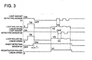
- Fig. 3 is a time chart for explaining the conveyance process of the transfer material in the loop forming space.
- the loop forming rollers 74a and 74b rotate for a prescribed duration t (seconds) of time and then stop. This time t determines the amount of loop, from the time the central part of the transfer sheet arrives at the sheet detecting sensor S3 until the loop forming rollers 74a and 74b stop rotating.
- the drive of the registration roller 71 is started at a linear speed of V1 (the image formation speed) so as to match with the timing of the toner image on the intermediate transfer belt 20.
- V1 the image formation speed
- the drives of the loop formation rollers 74a and 74b are started.
- the loop formation roller 74a at which a larger amount of loop has been formed after the transfer material has struck against the nipping portion N is driven at a somewhat lower speed V2 than the linear speed V1, and the loop amount starts to decrease gradually.
- the drive of the loop formation roller 74b is made at a somewhat higher speed V3 than the linear speed V1, and the amount of loop starts to increase gradually.
- the loop forming rollers 74a and 74b by controlling the loop forming rollers 74a and 74b at a linear speed V2 lower than the linear speed V1 of the registration roller or at a linear speed V3 higher than the linear speed V1 of the registration roller, a very high accuracy is being obtained.
- a method of simplifying the control while reducing the accuracy slightly for example, there is also a method of controlling the speed of the loop forming roller to a speed faster than the linear speed of the registration roller 71, on the side at which the loop is not detected, that is, on the side in which the sheet feed has been delayed, and of controlling the speed of the loop forming roller on the-other side to be the same as the linear speed of the registration roller 71.
- control device carrying out, based on each of the results of detection by a plurality of loop amount detecting devices, control of the respective sheet conveyance speeds of the corresponding plurality of loop forming devices, it is possible to form loops in the sheet with an appropriate loop amount over the entire width of the sheet along a direction perpendicular to the sheet conveyance direction, and since the loop does not become smaller than the amount necessary for correcting the sheet skew, it is possible to carry out stable correction of sheet skew even if the sheet has a long length in the direction of conveying the sheet.
Landscapes
- Physics & Mathematics (AREA)
- General Physics & Mathematics (AREA)
- Registering Or Overturning Sheets (AREA)
- Paper Feeding For Electrophotography (AREA)
Claims (3)
- Appareil de formation d'images comprenant :une section formatrice d'image (1) servant à former une image sur une feuille (P) ;un dispositif de repérage (71) servant à envoyer une feuille (P) à la section formatrice d'image (1) après correction d'une mise en travers de la feuille (P) ;une pluralité de dispositifs formateurs de boucle (74a, 74h) ;un dispositif de réglage (B1) pour régler une vitesse de transport de feuille de chacune de la pluralité de dispositifs formateurs de boucle (74a, 74b) individuellement, etune pluralité de dispositifs détecteurs de quantité de boucles (S1, S2) qui sont positionnés à une pluralité d'emplacements le long de la largeur de la feuille (P) dans une direction perpendiculaire à la direction de transport de la feuille, la pluralité de dispositifs détecteurs de quantité de boucles (S1, S2) étant configurée pour détecter la quantité de boucles créées par chacun de la pluralité de dispositifs formateurs de boucle (74a, 74b), caractérisé en ce que :les dispositifs de ladite pluralité de dispositifs formateurs de boucle (74a, 74b) sont positionnés en amont du dispositif de repérage (71) et sont configurés pour former une boucle de la feuille (P) entre le dispositif de repérage (71) et la pluralité de dispositifs formateurs de boucle (74a, 74b) ;les dispositifs de ladite pluralité de dispositifs détecteurs de quantité de boucles (S1, S2) sont positionnés entre le dispositif de repérage (71) et la pluralité de dispositifs formateurs de boucle (74a, 74b) ; etle dispositif de réglage (B1) est configuré pour commander la vitesse de transport de feuille de chacun de la pluralité de dispositifs formateurs de boucle (74a, 74b) individuellement afin de maintenir la formation d'une boucle sur toute la largeur de la feuille (P) le long d'une direction perpendiculaire à la direction de transport de la feuille, en fonction d'un résultat de détection de chacun de la pluralité de dispositifs détecteurs de quantité de boucles (S1, S2) après que chacun de la pluralité de dispositifs formateurs de boucle (74a, 74b) a formé une boucle en amont du dispositif de repérage (71) de manière à corriger une mise en travers de la feuille (P) et après que le transport de la feuille (P) du dispositif de repérage (71) à la section formatrice d'image (1) a commencé.
- Appareil de formation d'images selon la revendication 1,
dans lequel la section de commande (B1) est configurée pour effectuer un réglage de sorte que, lorsque la quantité de boucles détectée par chacun des dispositifs détecteurs de quantité de boucles (S1, S2) est supérieure à une quantité de boucles prédéterminée, la vitesse de transport de chacun des dispositifs formateurs de boucle (74a, 74b) soit inférieure à la vitesse de transport du dispositif de repérage (71) et que, lorsque la quantité de boucles détectée par chacun des dispositifs détecteurs de quantité de boucles (S1, S2) est inférieure à une quantité de boucles prédéterminée, la vitesse de transport de chacun des dispositifs formateurs de boucle (74a, 74b) soit supérieure à la vitesse de transport du dispositif de repérage (71). - Appareil de formation d'images selon la revendication 2,
dans lequel le dispositif de réglage (B1) est configuré pour ajuster la quantité de boucles à prendre comme quantité de boucles prédéterminée en répétant le réglage.
Applications Claiming Priority (1)
| Application Number | Priority Date | Filing Date | Title |
|---|---|---|---|
| JP2006149481A JP2007322472A (ja) | 2006-05-30 | 2006-05-30 | 画像形成装置 |
Publications (2)
| Publication Number | Publication Date |
|---|---|
| EP1865385A1 EP1865385A1 (fr) | 2007-12-12 |
| EP1865385B1 true EP1865385B1 (fr) | 2010-11-17 |
Family
ID=38461771
Family Applications (1)
| Application Number | Title | Priority Date | Filing Date |
|---|---|---|---|
| EP07250873A Ceased EP1865385B1 (fr) | 2006-05-30 | 2007-03-02 | Appareil de formation d'images avec un mécanisme d'alignement d'une feuille |
Country Status (4)
| Country | Link |
|---|---|
| US (1) | US8050616B2 (fr) |
| EP (1) | EP1865385B1 (fr) |
| JP (1) | JP2007322472A (fr) |
| DE (1) | DE602007010539D1 (fr) |
Families Citing this family (9)
| Publication number | Priority date | Publication date | Assignee | Title |
|---|---|---|---|---|
| JP5079038B2 (ja) * | 2010-02-26 | 2012-11-21 | キヤノン株式会社 | プリント装置、シート処理装置およびシート巻取装置 |
| JP5825881B2 (ja) * | 2010-09-08 | 2015-12-02 | キヤノン株式会社 | 画像形成装置 |
| JP5849511B2 (ja) * | 2011-08-11 | 2016-01-27 | セイコーエプソン株式会社 | 搬送装置および印刷装置 |
| JP6206140B2 (ja) * | 2013-12-03 | 2017-10-04 | コニカミノルタ株式会社 | 画像形成装置 |
| US9557701B2 (en) * | 2015-02-20 | 2017-01-31 | Kabushiki Kaisha Toshiba | Sheet conveyance apparatus |
| JP6386628B2 (ja) * | 2016-10-19 | 2018-09-05 | キヤノンファインテックニスカ株式会社 | 原稿搬送装置、および画像読取装置 |
| JP6769266B2 (ja) * | 2016-11-30 | 2020-10-14 | コニカミノルタ株式会社 | 画像形成装置 |
| US10987915B2 (en) * | 2019-04-10 | 2021-04-27 | Xerox Corporation | Registration system with a spline and yoke |
| US12115750B2 (en) * | 2023-03-10 | 2024-10-15 | Delkor Systems, Inc. | Package blank normalizing system |
Family Cites Families (17)
| Publication number | Priority date | Publication date | Assignee | Title |
|---|---|---|---|---|
| US4941021A (en) * | 1986-01-10 | 1990-07-10 | Canon Kabushiki Kaisha | Image forming apparatus with recording material loop forming and control means |
| US5156391A (en) * | 1991-11-04 | 1992-10-20 | Xerox Corporation | Short paper path electronic deskew system |
| JPH0672585A (ja) | 1992-08-28 | 1994-03-15 | Canon Inc | 画像形成装置 |
| JPH07319241A (ja) * | 1994-05-23 | 1995-12-08 | Canon Inc | シ−ト材給送装置および画像形成装置 |
| US5681036A (en) * | 1994-10-07 | 1997-10-28 | Canon Kabushiki Kaisha | Sheet feeding device with control of skew-correction |
| JPH08217291A (ja) * | 1995-02-08 | 1996-08-27 | Canon Inc | シ−ト材搬送装置および画像形成装置 |
| US5543909A (en) * | 1995-04-03 | 1996-08-06 | Xerox Corporation | Two step, large latitude, stalled roll registration system |
| JP2000118783A (ja) * | 1998-10-16 | 2000-04-25 | Canon Inc | 画像形成装置 |
| JP3879305B2 (ja) * | 1999-02-17 | 2007-02-14 | 富士ゼロックス株式会社 | 画像形成装置および用紙束生成装置並びに画像形成装置を用いた用紙束の生成方法 |
| JP3863412B2 (ja) * | 2001-11-16 | 2006-12-27 | 東北リコー株式会社 | 給紙装置・印刷装置 |
| US6974128B2 (en) * | 2003-06-10 | 2005-12-13 | Xerox Corporation | Sheet registration deskew with plural arcuate independently repositionable baffles |
| US7128318B2 (en) | 2004-04-20 | 2006-10-31 | Xerox Corporation | Sheet registration deskew improvement system with a centrally pivotal baffle |
| US7243917B2 (en) * | 2004-05-27 | 2007-07-17 | Xerox Corporation | Print media registration using active tracking of idler rotation |
| JP4336634B2 (ja) * | 2004-09-06 | 2009-09-30 | キヤノン株式会社 | シート供給装置及び画像形成装置 |
| US7310108B2 (en) * | 2004-11-30 | 2007-12-18 | Xerox Corporation | Printing system |
| JP4994768B2 (ja) * | 2005-12-09 | 2012-08-08 | キヤノン株式会社 | 画像形成装置 |
| US7690651B2 (en) * | 2006-02-03 | 2010-04-06 | Canon Kabushiki Kaisha | Image forming apparatus and remaining sheet detection method thereof |
-
2006
- 2006-05-30 JP JP2006149481A patent/JP2007322472A/ja active Pending
-
2007
- 2007-03-02 DE DE602007010539T patent/DE602007010539D1/de active Active
- 2007-03-02 US US11/713,500 patent/US8050616B2/en not_active Expired - Fee Related
- 2007-03-02 EP EP07250873A patent/EP1865385B1/fr not_active Ceased
Also Published As
| Publication number | Publication date |
|---|---|
| EP1865385A1 (fr) | 2007-12-12 |
| US20070280763A1 (en) | 2007-12-06 |
| US8050616B2 (en) | 2011-11-01 |
| JP2007322472A (ja) | 2007-12-13 |
| DE602007010539D1 (de) | 2010-12-30 |
Similar Documents
| Publication | Publication Date | Title |
|---|---|---|
| EP1865385B1 (fr) | Appareil de formation d'images avec un mécanisme d'alignement d'une feuille | |
| JP4038328B2 (ja) | 画像形成装置、転写材搬送方法及び転写装置 | |
| JP3978837B2 (ja) | 画像形成装置 | |
| US4941021A (en) | Image forming apparatus with recording material loop forming and control means | |
| US8983361B2 (en) | Image forming apparatus with sheet transport control timing changed according to length of transported sheet | |
| JP2759649B2 (ja) | 画像形成装置 | |
| US8042806B2 (en) | Image forming apparatus | |
| JP4213854B2 (ja) | シート搬送装置および画像形成装置 | |
| JPH0999601A (ja) | 画像形成装置 | |
| US12116234B2 (en) | Medium transport device and medium processing apparatus including the same | |
| JPH10161441A (ja) | 画像形成装置 | |
| JP7625477B2 (ja) | 画像形成装置 | |
| JP3776398B2 (ja) | 画像形成装置 | |
| JP3762147B2 (ja) | シート給紙搬送装置および画像形成装置 | |
| JP3670701B2 (ja) | 画像形成装置 | |
| US20250164917A1 (en) | Sheet conveyance apparatus and image forming apparatus | |
| JP5514757B2 (ja) | 画像形成装置 | |
| JP7341776B2 (ja) | 画像形成装置 | |
| JP2002156802A (ja) | 画像形成装置 | |
| JP3256000B2 (ja) | 画像形成装置 | |
| JP3522576B2 (ja) | 画像形成装置 | |
| JP2023112977A (ja) | 画像形成装置 | |
| JP2025039236A (ja) | 画像形成装置 | |
| JPH08286444A (ja) | 用紙搬送装置 | |
| JPH09114306A (ja) | 画像形成装置 |
Legal Events
| Date | Code | Title | Description |
|---|---|---|---|
| PUAI | Public reference made under article 153(3) epc to a published international application that has entered the european phase |
Free format text: ORIGINAL CODE: 0009012 |
|
| AK | Designated contracting states |
Kind code of ref document: A1 Designated state(s): AT BE BG CH CY CZ DE DK EE ES FI FR GB GR HU IE IS IT LI LT LU LV MC MT NL PL PT RO SE SI SK TR |
|
| AX | Request for extension of the european patent |
Extension state: AL BA HR MK YU |
|
| 17P | Request for examination filed |
Effective date: 20080604 |
|
| AKX | Designation fees paid |
Designated state(s): DE FR GB |
|
| GRAP | Despatch of communication of intention to grant a patent |
Free format text: ORIGINAL CODE: EPIDOSNIGR1 |
|
| GRAS | Grant fee paid |
Free format text: ORIGINAL CODE: EPIDOSNIGR3 |
|
| GRAA | (expected) grant |
Free format text: ORIGINAL CODE: 0009210 |
|
| AK | Designated contracting states |
Kind code of ref document: B1 Designated state(s): DE FR GB |
|
| REG | Reference to a national code |
Ref country code: GB Ref legal event code: FG4D |
|
| REF | Corresponds to: |
Ref document number: 602007010539 Country of ref document: DE Date of ref document: 20101230 Kind code of ref document: P |
|
| PLBE | No opposition filed within time limit |
Free format text: ORIGINAL CODE: 0009261 |
|
| STAA | Information on the status of an ep patent application or granted ep patent |
Free format text: STATUS: NO OPPOSITION FILED WITHIN TIME LIMIT |
|
| 26N | No opposition filed |
Effective date: 20110818 |
|
| REG | Reference to a national code |
Ref country code: DE Ref legal event code: R097 Ref document number: 602007010539 Country of ref document: DE Effective date: 20110818 |
|
| REG | Reference to a national code |
Ref country code: FR Ref legal event code: PLFP Year of fee payment: 10 |
|
| REG | Reference to a national code |
Ref country code: FR Ref legal event code: PLFP Year of fee payment: 11 |
|
| PGFP | Annual fee paid to national office [announced via postgrant information from national office to epo] |
Ref country code: FR Payment date: 20170213 Year of fee payment: 11 Ref country code: DE Payment date: 20170221 Year of fee payment: 11 |
|
| PGFP | Annual fee paid to national office [announced via postgrant information from national office to epo] |
Ref country code: GB Payment date: 20170301 Year of fee payment: 11 |
|
| REG | Reference to a national code |
Ref country code: DE Ref legal event code: R119 Ref document number: 602007010539 Country of ref document: DE |
|
| GBPC | Gb: european patent ceased through non-payment of renewal fee |
Effective date: 20180302 |
|
| PG25 | Lapsed in a contracting state [announced via postgrant information from national office to epo] |
Ref country code: DE Free format text: LAPSE BECAUSE OF NON-PAYMENT OF DUE FEES Effective date: 20181002 |
|
| PG25 | Lapsed in a contracting state [announced via postgrant information from national office to epo] |
Ref country code: GB Free format text: LAPSE BECAUSE OF NON-PAYMENT OF DUE FEES Effective date: 20180302 |
|
| PG25 | Lapsed in a contracting state [announced via postgrant information from national office to epo] |
Ref country code: FR Free format text: LAPSE BECAUSE OF NON-PAYMENT OF DUE FEES Effective date: 20180331 |