EP1865595A2 - Elektronisches Brems- und Energierückgewinnungssystem in Verbindung mit einem bürstenlosen Gleichstrommotor - Google Patents
Elektronisches Brems- und Energierückgewinnungssystem in Verbindung mit einem bürstenlosen Gleichstrommotor Download PDFInfo
- Publication number
- EP1865595A2 EP1865595A2 EP07109632A EP07109632A EP1865595A2 EP 1865595 A2 EP1865595 A2 EP 1865595A2 EP 07109632 A EP07109632 A EP 07109632A EP 07109632 A EP07109632 A EP 07109632A EP 1865595 A2 EP1865595 A2 EP 1865595A2
- Authority
- EP
- European Patent Office
- Prior art keywords
- motor
- current
- electronic braking
- energy recycling
- braking
- Prior art date
- Legal status (The legal status is an assumption and is not a legal conclusion. Google has not performed a legal analysis and makes no representation as to the accuracy of the status listed.)
- Withdrawn
Links
Images


Classifications
-
- H—ELECTRICITY
- H02—GENERATION; CONVERSION OR DISTRIBUTION OF ELECTRIC POWER
- H02P—CONTROL OR REGULATION OF ELECTRIC MOTORS, ELECTRIC GENERATORS OR DYNAMO-ELECTRIC CONVERTERS; CONTROLLING TRANSFORMERS, REACTORS OR CHOKE COILS
- H02P6/00—Arrangements for controlling synchronous motors or other dynamo-electric motors using electronic commutation dependent on the rotor position; Electronic commutators therefor
- H02P6/24—Arrangements for stopping
Definitions
- the present invention relates to an electronic braking and energy recycling system associated with a direct current (DC) brushless motor, which can achieve a controllable inverse torsion or damping force, for motor braking by using a set of specially defined simple gate signals.
- DC direct current
- this present invention can obtain a theoretically maximum recycling proportion of a dynamic power, without the need of altering any hardware structure of the conventional system of this kind.
- a DC brush motor has the advantages of easy control, owing to the only one set of equivalent internal windings, and lower cost of a controller thereof although it has the problem of powder dust resulted from a carbon brush and a carbon brush resistance.
- the high power metal oxide semiconductor field effect transistor MOSFET
- the electronic braking is not solely aimed at providing the friction needed during speed decreasing of the vehicle. At this time, the electronic braking system is expected to become a subject in the field of the reliable and high efficient DC brushless motor.
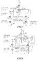
- FIG. 1, FIG. 2 and FIG. 3 Since only a single equivalent coil exists within the DC brush motor, the direction of a torsion of the motor is determined by the direction of the electrical current flown through this single coil. The direction of the electrical current flown through the coil, i.e. the direction of the torsion of the motor, can be readily determined by the switch-on/off states of the four MOSFETs shown in FIG. 1.
- an induced voltage on the equivalent coil of the motor is approximately proportional to a rotation speed of the motor, the induced voltage of the motor is relatively larger as the vehicle braked from a high speed, and even equals to the battery voltage as under the maximum motor speed.
- turning on any lower-side MOSFET will makes the induced voltage magnetizing the inductor of this equivalent coil.
- an induced electromotive force produced by the magnetized inductor will force the inertial current to flow through the body diodes of the MOSFETs, forwarding the electrical energy back to the electrical power side.
- the increased range of the inverse torsion has to be carefully controlled and the mechanic braking system has to be suitably provided, so that the electro-activated vehicle would not move backwards during braking.
- the conventional electronic brake system does not consider the issue of energy recycling but only aims to the efficient control of the electrical machine.
- the conventional brush control system can only provide the braking function without appropriately saving the supplied electrical energy.
- the motor has three-phase windings, which are inherently difficult to be used for electronic braking or energy recycling.
- the motor can be traditionally considered as an inductor on which an induced voltage presents, which reflects the rotation speed of the motor.
- MOSFET and BJT solid switch-relay or other electronic switch, such as MOSFET and BJT, so that the dynamic power can be redirected back to the battery corresponding to the induced voltage or a super capacitor. In this way, it is operated by restoring the dynamic power back to the electrical energy and controlled only based on the detected induced voltage.
- the control mechanism of the DC brush motor onto the DC brushless motor is likely to be those shown in FIG 5 and FIG 6.
- the different control mechanisms correspond to the induced voltages associated with high and low speeds have to be provided concurrently.
- the torsion increases dramatically, resulting in a low proportion of energy recycling.
- the braking function can only be achieved by resorting to a mechanical design.
- a bi-directional current sensor has to be built to detect the magnitude of the inverse current flown through the coil. More importantly, this braking mechanism can only be effective under the situation where the other two phases of the motor does not produce any other induced current owing to the induced voltage of the subject phase and thus interfere the control mechanism as previously designed.
- the present invention discloses an electronic braking and energy recycling system associated with a direct current (DC) brushless motor, which can particularly achieves a controllable inverse torsion or damping force for motor braking by using a set of simple gate signals with positive and negative cycles for controlling operations of respective MOSFETs on upper and lower-side branches (six combinations in total), which is not interfered by multi-phase coils, and thus obtains a maximum proportion of dynamic power recycling, without the need of altering any of a hardware structure of the conventional system.
- DC direct current
- the electronic braking and energy recycling system associated with direct current (DC) brushless motor is characterized in that when an electronic braking task is launched, a phase voltage occurred in an inverse mode is applied onto a motor coil corresponding thereto and a gate voltage signal with positive and negative cycles is used to control an upper-side and lower-side branches to switch, so as to redirect a current flown through the motor back to a power source end.
- a controllable inverse torsion is achieved, enabling an electrical machine to be braked smoothly and reliably when necessary.
- the dynamic power of the motor can be recycled at a maximum rate and thus the purpose of energy recycling is achieved.
- no complex circuitry configuration owing to the multi-phase coils is required.
- the present invention discloses an electronic braking and energy recycling system associated with DC brushless motor, which can provide an inverse torsion-based braking function by using a conversion of gate voltages under the condition without altering the conventional motor controller and any hardware configuration of the motor. Further, the inventive system can achieve the maximum recycling ratio for the dynamic power of the motor without being interfered with the multi-phase coil.
- the DC brushless motor is shown therein, in which a current is shown as flowing through a coil of the motor with the flow direction thereof also indicated.
- a controller applies a voltage associated with an inverse mode onto the indicated motor coil.
- the only difference is that a MOSFET on a lower-side branch at the left part is not always maintained in "ON" status. Instead, the mentioned MOSFET on the lower-side branch is operated in a synchronous switching state with a MOSFET on an upper-side branch at the right part. In this manner, the current flown through the motor coil can be redirected back to a power end as the MOSFETs of the upper and lower-side branches are turned off.
- FIG. 9 in which the electronic braking and energy recycling system according to an embodiment of the present invention is depicted.
- the system embodiment is a simple example of use thereof.
- the basic structure of this embodiment is obtained from the patents TW251395 and US6,960,896 , except that the braking function is implemented by the signals for emergent stop used in these two patents.
- Logic gate 1 gate array logic, GAL
- GAL gate array logic
- Logic gate 1 is also used to provide accurate phase signals associated with the three-phase upper and lower-side branches when a braking signal is inputted.
- a micro-control unit 2 is configured to converse a torsion command into a current command and monitor a safety issue of the system by using a power control technology.
- a simple shunt is use to converse the current signal into a voltage signal. This voltage signal is then amplified and transmitted to a comparator 3. Finally, an output from the comparator 3 is forwarded to a current mode pulse width modulation (PWM) controller, ST3842, 4, in which the output from the comparator 3 is served as a reference for a PWM process.
- PWM pulse width modulation
- FIG. 10 is a schematic diagram of a current waveform as recycled obtained from the embodiment shown in FIG. 9.
- the positive current means the current is flowed from the power source to the electrical system and thus an energy output
- the negative current means the current is flowed from the electrical system to the power source and this an energy recycling. It can be appreciated that the proportion of the energy recycling is almost a constant value when the motor rotates at a constant speed.
Landscapes
- Engineering & Computer Science (AREA)
- Power Engineering (AREA)
- Control Of Motors That Do Not Use Commutators (AREA)
Applications Claiming Priority (1)
| Application Number | Priority Date | Filing Date | Title |
|---|---|---|---|
| CNA2006100915881A CN101085602A (zh) | 2006-06-07 | 2006-06-07 | 使用于无刷直流马达的电子刹车暨能源回收系统 |
Publications (2)
| Publication Number | Publication Date |
|---|---|
| EP1865595A2 true EP1865595A2 (de) | 2007-12-12 |
| EP1865595A3 EP1865595A3 (de) | 2010-07-14 |
Family
ID=38515545
Family Applications (1)
| Application Number | Title | Priority Date | Filing Date |
|---|---|---|---|
| EP07109632A Withdrawn EP1865595A3 (de) | 2006-06-07 | 2007-06-05 | Elektronisches Brems- und Energierückgewinnungssystem in Verbindung mit einem bürstenlosen Gleichstrommotor |
Country Status (2)
| Country | Link |
|---|---|
| EP (1) | EP1865595A3 (de) |
| CN (1) | CN101085602A (de) |
Families Citing this family (3)
| Publication number | Priority date | Publication date | Assignee | Title |
|---|---|---|---|---|
| TWI424679B (zh) * | 2011-04-08 | 2014-01-21 | Ind Tech Res Inst | 具能量回收之無感測元件馬達控制方法 |
| CN110435438A (zh) * | 2018-05-04 | 2019-11-12 | 台州市迷你摩托斯车业有限公司 | 一种电动车使用的abs系统 |
| TWI703797B (zh) * | 2018-09-28 | 2020-09-01 | 黃柏原 | 一種可蓄電無刷直流馬達電路裝置 |
Family Cites Families (5)
| Publication number | Priority date | Publication date | Assignee | Title |
|---|---|---|---|---|
| US4544868A (en) * | 1984-07-20 | 1985-10-01 | General Motors Corporation | Brushless DC motor controller |
| CN1213532C (zh) * | 1998-12-30 | 2005-08-03 | 皇家菲利浦电子有限公司 | 用于驱动多相直流电机的装置 |
| KR100406875B1 (ko) * | 1999-03-22 | 2003-11-21 | 페어차일드코리아반도체 주식회사 | 모터의 제어 회로 및 제어 방법 |
| EP1207618B1 (de) * | 2000-11-20 | 2005-10-05 | STMicroelectronics S.r.l. | Schaltkreis zur Rückgewinnung von Geschwindigkeit eines Gleichstrommotors und Verfahren zum Benutzen dieses Schaltkreises |
| TWM251395U (en) * | 2004-02-16 | 2004-11-21 | Welltek Energy Technology Comp | Programmable fast motor torque controller |
-
2006
- 2006-06-07 CN CNA2006100915881A patent/CN101085602A/zh active Pending
-
2007
- 2007-06-05 EP EP07109632A patent/EP1865595A3/de not_active Withdrawn
Also Published As
| Publication number | Publication date |
|---|---|
| EP1865595A3 (de) | 2010-07-14 |
| CN101085602A (zh) | 2007-12-12 |
Similar Documents
| Publication | Publication Date | Title |
|---|---|---|
| US7560884B2 (en) | Electronic braking and energy recycling system associated with DC brushless motor | |
| US6528968B2 (en) | Brushless-motor driver in PWM mode | |
| US5166591A (en) | Current chopping strategy for generating action in switched reluctance machines | |
| US5864477A (en) | Converter circuit for a polyphase switched inductive load | |
| JP5858309B2 (ja) | 電力変換システム及びその制御方法 | |
| CN1292602A (zh) | 用于制动洗衣机的方法 | |
| WO2010026699A1 (ja) | 電力変換装置 | |
| KR20040041200A (ko) | 모터전원공급장치 및 모터전원공급방법 | |
| JP5288178B2 (ja) | モータ駆動システム | |
| JPH0956187A (ja) | 遠心機用モータの制御装置 | |
| EP3579399A1 (de) | Steuerungsverfahren und steuerungsvorrichtung für bürstenlosen gleichstrommotor | |
| CN108306487B (zh) | 车辆中的可变电压转换器控制 | |
| US6870344B2 (en) | Motor control system | |
| US5436825A (en) | Electronic control circuit for the supply of ohmic-inductive loads by means of direct-current pulses | |
| EP1865595A2 (de) | Elektronisches Brems- und Energierückgewinnungssystem in Verbindung mit einem bürstenlosen Gleichstrommotor | |
| US8405366B2 (en) | Method for controlling generation of electrical power | |
| JP2013059192A (ja) | 電気自動車のコンデンサ電荷放電装置 | |
| JP5571987B2 (ja) | ブラシレスdcモータの制動方法 | |
| Naresh et al. | Comparative Analysis of High Gain Boost Converter (HGBC) fed BLDC Motor | |
| CN111865178A (zh) | 功率转换器 | |
| WO2008068541A1 (en) | Method and control unit for equipment using electrical energy | |
| JP2021065074A (ja) | モータ制御装置 | |
| US11491879B2 (en) | Sequential electrical braking with pulsed DC injection rotor lock mechanism | |
| TWI425762B (zh) | Power generation control method | |
| Vamsi et al. | Multi quadrant operation of BLDC motor-driven electric hybrid vehicle |
Legal Events
| Date | Code | Title | Description |
|---|---|---|---|
| PUAI | Public reference made under article 153(3) epc to a published international application that has entered the european phase |
Free format text: ORIGINAL CODE: 0009012 |
|
| AK | Designated contracting states |
Kind code of ref document: A2 Designated state(s): AT BE BG CH CY CZ DE DK EE ES FI FR GB GR HU IE IS IT LI LT LU LV MC MT NL PL PT RO SE SI SK TR |
|
| AX | Request for extension of the european patent |
Extension state: AL BA HR MK YU |
|
| PUAL | Search report despatched |
Free format text: ORIGINAL CODE: 0009013 |
|
| AK | Designated contracting states |
Kind code of ref document: A3 Designated state(s): AT BE BG CH CY CZ DE DK EE ES FI FR GB GR HU IE IS IT LI LT LU LV MC MT NL PL PT RO SE SI SK TR |
|
| AX | Request for extension of the european patent |
Extension state: AL BA HR MK RS |
|
| AKY | No designation fees paid | ||
| REG | Reference to a national code |
Ref country code: DE Ref legal event code: R108 Effective date: 20110222 Ref country code: DE Ref legal event code: 8566 |
|
| STAA | Information on the status of an ep patent application or granted ep patent |
Free format text: STATUS: THE APPLICATION IS DEEMED TO BE WITHDRAWN |
|
| 18D | Application deemed to be withdrawn |
Effective date: 20110115 |