EP1865889B1 - Verbindungsband und druckabsorbierender rahmen für eine hochflexible herzklappe - Google Patents
Verbindungsband und druckabsorbierender rahmen für eine hochflexible herzklappe Download PDFInfo
- Publication number
- EP1865889B1 EP1865889B1 EP06749397A EP06749397A EP1865889B1 EP 1865889 B1 EP1865889 B1 EP 1865889B1 EP 06749397 A EP06749397 A EP 06749397A EP 06749397 A EP06749397 A EP 06749397A EP 1865889 B1 EP1865889 B1 EP 1865889B1
- Authority
- EP
- European Patent Office
- Prior art keywords
- heart valve
- connecting band
- commissure
- commissures
- cusp
- Prior art date
- Legal status (The legal status is an assumption and is not a legal conclusion. Google has not performed a legal analysis and makes no representation as to the accuracy of the status listed.)
- Expired - Lifetime
Links
Images


Classifications
-
- A—HUMAN NECESSITIES
- A61—MEDICAL OR VETERINARY SCIENCE; HYGIENE
- A61F—FILTERS IMPLANTABLE INTO BLOOD VESSELS; PROSTHESES; DEVICES PROVIDING PATENCY TO, OR PREVENTING COLLAPSING OF, TUBULAR STRUCTURES OF THE BODY, e.g. STENTS; ORTHOPAEDIC, NURSING OR CONTRACEPTIVE DEVICES; FOMENTATION; TREATMENT OR PROTECTION OF EYES OR EARS; BANDAGES, DRESSINGS OR ABSORBENT PADS; FIRST-AID KITS
- A61F2/00—Filters implantable into blood vessels; Prostheses, i.e. artificial substitutes or replacements for parts of the body; Appliances for connecting them with the body; Devices providing patency to, or preventing collapsing of, tubular structures of the body, e.g. stents
- A61F2/02—Prostheses implantable into the body
- A61F2/24—Heart valves ; Vascular valves, e.g. venous valves; Heart implants, e.g. passive devices for improving the function of the native valve or the heart muscle; Transmyocardial revascularisation [TMR] devices; Valves implantable in the body
- A61F2/2412—Heart valves ; Vascular valves, e.g. venous valves; Heart implants, e.g. passive devices for improving the function of the native valve or the heart muscle; Transmyocardial revascularisation [TMR] devices; Valves implantable in the body with soft flexible valve members, e.g. tissue valves shaped like natural valves
- A61F2/2418—Scaffolds therefor, e.g. support stents
-
- A—HUMAN NECESSITIES
- A61—MEDICAL OR VETERINARY SCIENCE; HYGIENE
- A61F—FILTERS IMPLANTABLE INTO BLOOD VESSELS; PROSTHESES; DEVICES PROVIDING PATENCY TO, OR PREVENTING COLLAPSING OF, TUBULAR STRUCTURES OF THE BODY, e.g. STENTS; ORTHOPAEDIC, NURSING OR CONTRACEPTIVE DEVICES; FOMENTATION; TREATMENT OR PROTECTION OF EYES OR EARS; BANDAGES, DRESSINGS OR ABSORBENT PADS; FIRST-AID KITS
- A61F2/00—Filters implantable into blood vessels; Prostheses, i.e. artificial substitutes or replacements for parts of the body; Appliances for connecting them with the body; Devices providing patency to, or preventing collapsing of, tubular structures of the body, e.g. stents
- A61F2/02—Prostheses implantable into the body
- A61F2/24—Heart valves ; Vascular valves, e.g. venous valves; Heart implants, e.g. passive devices for improving the function of the native valve or the heart muscle; Transmyocardial revascularisation [TMR] devices; Valves implantable in the body
- A61F2/2409—Support rings therefor, e.g. for connecting valves to tissue
-
- A—HUMAN NECESSITIES
- A61—MEDICAL OR VETERINARY SCIENCE; HYGIENE
- A61F—FILTERS IMPLANTABLE INTO BLOOD VESSELS; PROSTHESES; DEVICES PROVIDING PATENCY TO, OR PREVENTING COLLAPSING OF, TUBULAR STRUCTURES OF THE BODY, e.g. STENTS; ORTHOPAEDIC, NURSING OR CONTRACEPTIVE DEVICES; FOMENTATION; TREATMENT OR PROTECTION OF EYES OR EARS; BANDAGES, DRESSINGS OR ABSORBENT PADS; FIRST-AID KITS
- A61F2220/00—Fixations or connections for prostheses classified in groups A61F2/00 - A61F2/26 or A61F2/82 or A61F9/00 or A61F11/00 or subgroups thereof
- A61F2220/0025—Connections or couplings between prosthetic parts, e.g. between modular parts; Connecting elements
- A61F2220/005—Connections or couplings between prosthetic parts, e.g. between modular parts; Connecting elements using adhesives
-
- A—HUMAN NECESSITIES
- A61—MEDICAL OR VETERINARY SCIENCE; HYGIENE
- A61F—FILTERS IMPLANTABLE INTO BLOOD VESSELS; PROSTHESES; DEVICES PROVIDING PATENCY TO, OR PREVENTING COLLAPSING OF, TUBULAR STRUCTURES OF THE BODY, e.g. STENTS; ORTHOPAEDIC, NURSING OR CONTRACEPTIVE DEVICES; FOMENTATION; TREATMENT OR PROTECTION OF EYES OR EARS; BANDAGES, DRESSINGS OR ABSORBENT PADS; FIRST-AID KITS
- A61F2220/00—Fixations or connections for prostheses classified in groups A61F2/00 - A61F2/26 or A61F2/82 or A61F9/00 or A61F11/00 or subgroups thereof
- A61F2220/0025—Connections or couplings between prosthetic parts, e.g. between modular parts; Connecting elements
- A61F2220/0066—Connections or couplings between prosthetic parts, e.g. between modular parts; Connecting elements stapled
-
- A—HUMAN NECESSITIES
- A61—MEDICAL OR VETERINARY SCIENCE; HYGIENE
- A61F—FILTERS IMPLANTABLE INTO BLOOD VESSELS; PROSTHESES; DEVICES PROVIDING PATENCY TO, OR PREVENTING COLLAPSING OF, TUBULAR STRUCTURES OF THE BODY, e.g. STENTS; ORTHOPAEDIC, NURSING OR CONTRACEPTIVE DEVICES; FOMENTATION; TREATMENT OR PROTECTION OF EYES OR EARS; BANDAGES, DRESSINGS OR ABSORBENT PADS; FIRST-AID KITS
- A61F2220/00—Fixations or connections for prostheses classified in groups A61F2/00 - A61F2/26 or A61F2/82 or A61F9/00 or A61F11/00 or subgroups thereof
- A61F2220/0025—Connections or couplings between prosthetic parts, e.g. between modular parts; Connecting elements
- A61F2220/0075—Connections or couplings between prosthetic parts, e.g. between modular parts; Connecting elements sutured, ligatured or stitched, retained or tied with a rope, string, thread, wire or cable
Definitions
- the present invention relates to prosthetic heart valves, and, more particularly, to a highly flexible prosthetic tissue valve, connecting band or sewing ring, and associated support frame.
- Prosthetic heart valves are used to replace damaged or diseased heart valves.
- the heart is a hollow muscular organ having four pumping chambers: the left and right atria and the left and right ventricles, each provided with its own one-way outflow valve.
- the natural heart valves are identified as the aortic, mitral (or bicuspid), tricuspid and pulmonary valves.
- the valves of the heart separate chambers therein, and are each mounted in an annulus therebetween.
- the annuluses comprise dense fibrous rings attached either directly or indirectly to the atrial and ventricular muscle fibers.
- Prosthetic heart valves can be used to replace any of these naturally occurring valves, although repair or replacement of the aortic or mitral valves are most common because they reside in the left side of the heart where pressures are the greatest.
- a valve replacement operation the damaged leaflets are excised and the annulus sculpted to receive a replacement valve.
- the four valves separate each ventricle from its associated atrium, or from the ascending aorta (left ventricle) or pulmonary artery (right ventricle).
- the annulus After the valve excision, the annulus generally comprises a ledge extending into and defining the orifice between the respective chambers.
- Prosthetic valves may attach on the upstream or downstream sides of the annulus ledge, but outside of the ventricles to avoid interfering with the large contractions therein.
- a prosthetic valve is positioned on the inflow side of the mitral valve annulus (in the left atrium), or on the outflow side of the aortic valve annulus (in the ascending aorta).
- Two primary types of heart valve replacements or prostheses are known.
- One is a mechanical-type heart valve that uses a ball and cage arrangement or a pivoting mechanical closure to provide unidirectional blood flow.
- the other is a tissue-type or "bioprosthetic" valve which is constructed with natural-tissue valve leaflets which function much like a natural human heart valve, imitating the natural action of the flexible heart valve leaflets which seal against each other to ensure the one-way blood flow.
- Prosthetic tissue valves typically comprise a stent having a rigid, annular ring portion and a plurality of upstanding commissures to which an intact xenograft valve or separate leaflets of, for example, bovine pericardium are attached. Fabric covers a majority of the structure and a suture-permeable sewing ring is provided around the periphery for attaching to the natural annulus. Because of the rigidity of the material used in the stent and/or wireform, conventional valves have a diameter that is minimally affected by the natural motion of the heart orifice. In the aortic position, the prosthetic valve commissures extend axially in the downstream direction a spaced distance from the walls of the downstream aortic wall.
- Movement of the aortic wall or sinuses does not directly affect movement of the cantilevered commissures, though fluid flow and pressures generated by movement of the walls ultimately does cause the commissures to dynamically flex to some extent (i.e., they are cantilevered downstream in the aorta). Because of the inherent rigidity in conventional heart valves, the natural dilatation of the annulus is restricted, imposing an artificial narrowing of the orifice, and increasing the pressure drop therethrough.
- U.S. Patent No. 6,558,418 to Carpentier, et al. discloses a flexible heart valve especially suitable for implant in the aortic position.
- a single or multielement stent includes commissures constructed so that the cusps are pivotably or flexibly coupled together to permit relative movement therebetween.
- An undulating suture-permeable connecting band attached to the valve follows the cusps and commissures and extends outwardly such that the valve may be connected to the natural tissue using conventional techniques.
- the connecting band may be cloth-covered silicon and provides support to the stent and to the outer side of the valve at the commissures while still permitting the cusps to flex with respect to one another.
- US 2004/0059413 to Argento discloses a suture template for facilitating implantation of a prosthetic heart valve in a patient.
- the suture template comprises commissure portions and cusp portions, together with additional structural features which aid the surgeon in accurately placing the sutures necessary for a prosthetic heart valve, and removing the suture template.
- the present invention provides a flexible support frame for a prosthetic heart valve having commissure tips that are shaped to even out stresses imposed during use.
- the support frame is an elongated wire-like element formed by a plurality, typically three, of arcuate cusp regions on an inflow end alternating with the same number of commissures terminating in tips on an outflow end.
- the commissure tips are elongated relative to more simple shapes.
- the commissure tips may be shaped with a complex curve having two enlarged convex flexure portions separated by a concave bridge portion at the midpoint of the commissure tip.
- the support frame may be fabricated by separating a two-dimensional blank from a sheet and then converting the blank into a three-dimensional support frame shape.
- the cross-sectional thickness of the support frame is variable, such as by adjusting the thickness of the pattern of the two-dimensional blank in the sheet. Desirably, the radial thickness remains constant while the circumferential dimension varies with a maximum located at the commissure
- a stress-absorbing flexible support frame for a prosthetic heart valve is provided.
- the support frame is formed by an elongated wire-like element generally describing a tube around an axis and having a plurality, typically three, of arcuate cusp regions on an inflow end alternating with the same number of commissures terminating in tips on an outflow end.
- the arcuate cusp regions are convex toward the inflow end and the commissure tips are generally convex toward the outflow end.
- Each cusp terminates on opposite ends at commissure regions extending from the cusp regions in the outflow direction wherein two adjacent commissure regions extending from adjacent cusp regions converge toward each of the commissure tips.
- Each commissure tip includes a pair of arcuate outer flexure portions projecting in the outflow direction connected by an oppositely-curved inner bridge portion.
- each commissure tip may resemble mouse ears.
- the flexure portions desirably possess a relatively large radius of curvature relative to a simple inverted U-shape between adjacent commissure regions.
- the adjacent commissure regions converge toward a smallest gap of dimension X, and the length around each commissure tip is no less than 6X.
- the cross-section of the flexure portions is designed to absorb bending stresses at the commissure tips.
- the flexure portions may have a larger cross-section than the bridge portion, and also may have a larger cross-section that the commissure regions.
- the bridge portions are designed to break after certain number of movement cycles of the stent.
- a stress-absorbing flexible support frame for a prosthetic heart valve comprises an elongated wire-like element generally describing a tube around an axis.
- the support frame has a plurality, typically three, of arcuate cusp regions on an inflow end alternating with the same number of commissures terminating in tips on an outflow end, the arcuate cusp regions being convex toward the inflow end and the commissure tips being generally convex toward the outflow end.
- Each cusp terminates on opposite ends at commissure regions extending from the cusp regions in the outflow direction wherein two adjacent commissure regions extending from adjacent cusp regions converge toward each of the commissure tips.
- the adjacent commissure regions converge toward a smallest gap of dimension X, and wherein the length around each commissure tip is no less than 6X.
- each commissure tip defines a complex curve with at least two convex portions separated by a concave bridge portion at the midpoint of the commissure tip.
- the shape of each commissure tip resembles mouse ears.
- the flexure portions have a larger cross-section than the bridge portion, and also a larger cross-section than the commissure regions.
- a stress-absorbing flexible support frame for a prosthetic heart valve comprises an elongated wire-like element generally describing a tube around an axis.
- the support frame has a plurality, typically three, of arcuate cusp regions on an inflow end alternating with the same number of commissures terminating in tips on an outflow end, the arcuate cusp regions being convex toward the inflow end and the commissure tips being generally convex toward the outflow end.
- Each cusp terminates on opposite ends at commissure regions extending from the cusp regions in the outflow direction wherein two adjacent commissure regions extending from adjacent cusp regions converge toward each of the commissure tips.
- each commissure tip defines a complex curve with at least two convex portions separated by a concave bridge portion at the midpoint of the commissure tip.
- the flexure portions may have a larger cross-section than either the bridge portion or the commissure regions.
- the support frame has a constant radial dimension and a varying circumferential dimension.
- the cross-section of the support frame may be substantially rectangular throughout.
- the support frame is fabricated by separating a blank from a two-dimensional sheet and then converting the two-dimensional blank into a three-dimensional support frame shape.
- the present application further discloses a connecting band for a flexible heart valve that improves on earlier designs.
- the connecting band follows the cusps and commissures and extends outwardly.
- the valve is connected to the natural tissue along the undulating connecting band using conventional techniques, such as sutures.
- the connecting band may be a cloth-covered inner suture-permeable member and attaches to the underside of the valve at the cusps to provide support to the stent and to the outer side of the valve at the commissures.
- the connecting band includes commissure portions defining generally axial gaps that help permit flexing of the valve.
- the connecting band features relief slits on the inner curvature of the cusps to facilitate flexing thereof.
- the connecting band includes a more robust construction on the inflow side thereof that facilitates a supra-annular implant technique.
- the inner member may further include a continuous outwardly projecting sewing ridge around its periphery which includes a series of ribs separated by grooves around the inflow edge of the cusps.
- the present invention provides a suture-permeable connecting band for securing a prosthetic heart valve to an anatomical cavity.
- the connecting band is flexible and has a continuous undulating shape generally defining a tube with alternating inflow cusps and outflow commissures, the cusps having large radii of curvatures relative to the commissures.
- An inflow edge of the connecting band substantially conforms to an outflow edge thereof and follows the undulating shape such that axial gaps are created between adjacent cusps at the commissures.
- the axial gaps having a height of at least about 50% of the overall axial height of the connecting band.
- Each cusp has a varying cross-section between adjacent commissures that includes at least one relief point at which the cross-section abruptly reduces such that bending of each connecting band cusp occurs first at the relief point.
- the connecting band may be molded of silicone rubber.
- the relief point in each connecting band cusp comprises a generally radial slit. Desirably, there are a plurality of generally radial slits in each connecting band cusp, more preferably between about 5-7 slits. In an alternative version, the relief point in each connecting band cusp comprises a generally radial groove. Desirably, an inflow edge of each connecting band cusp comprises at least two generally radially-directed ribs separated by the generally radial groove.
- a plurality of generally radially-directed ribs and grooves may be provided that are angled toward the inflow direction, wherein the size of the ribs and grooves diminishes from a maximum at an apex of the cusps until they disappear prior to the commissures.
- a suture-permeable connecting band for securing a prosthetic heart valve to an anatomical cavity, comprises a flexible, continuous connecting band having an inflow end and an outflow end.
- the connecting band exhibits an undulating shape generally circumscribing a tube with alternating inflow cusps and outflow commissures, the cusps having large radii of curvatures relative to the commissures.
- An inflow edge of the connecting band substantially conforms to an outflow edge thereof and follows the undulating shape such that axial gaps are created between adjacent cusps at the commissures, the gaps having a height of at least about 50% of the overall axial height of the connecting band.
- a continuous sewing ridge is provided around the periphery of the connecting band that is radially-outwardly directed at the commissures and larger and angled radially outward and toward the inflow end at the cusps.
- the sewing ridge facilitates supra-annular attachment of the prosthetic valve.
- the connecting band may define a free margin comprising a relatively narrow flap that angles radially outward and toward the outflow end at the cusps, and is substantially axially-aligned at the commissures. Desirably, the free margin gradually diminishes in size from each commissure to an apex of each cusp. At the commissures, the free margin extends outward from the sewing ridge.
- the sewing ridge at the cusps defines an inflow end of the connecting band and includes a plurality of alternating generally radial ribs and grooves.
- the size of the generally radial ribs varies and is greatest at an apex of each cusp, and a plurality of the alternating generally radial ribs and grooves may be provided, wherein the size of the ribs and grooves diminishes from a maximum at an apex of the cusps until they disappear prior to the commissures.
- a method of supra-annular implantation of a flexible aortic prosthetic heart valve includes providing a flexible aortic prosthetic heart valve having a supporting structure to which prosthetic leaflets attach and project radially inward and to which a connecting band attaches and projects generally radially outward.
- the supporting structure and connecting band each generally circumscribe a tube and has an undulating shape with alternating inflow cusps and outflow commissures.
- the cusps have large radii of curvatures relative to the commissures.
- An inflow edge of the valve substantially conforms to an outflow edge thereof and follows the undulating shape such that axial gaps are created between adjacent cusps at the commissures.
- the gaps have a height of at least about 50% of the overall axial height of the supporting structure, and a continuous outwardly directed sewing ridge facilitates supra-annular attachment of the prosthetic valve.
- the method includes first removing the native leaflets at their line of attachment, then delivering the prosthetic heart valve to an aortic annulus, and finally implanting the prosthetic heart valve to the aortic annulus by securing the connecting band exclusively to fibrous tissue along the line of native leaflet attachment.
- Each cusp of the connecting band may have a varying cross-section between adjacent commissures that includes at least one relief point at which the cross-section abruptly reduces such that bending of each connecting band cusp occurs first at the relief point.
- the relief point in each connecting band cusp may comprise a generally radial slit.
- the relief point in each connecting band cusp comprises a generally radial groove, and wherein an inflow edge of each connecting band cusp comprises at least two generally radially-directed ribs separated by the generally radial groove.
- the method includes securing the commissures of the prosthetic valve to the fibrous native leaflet commissures such that the valve cusps are subjected to bending forces in use and the radial slit or radial groove enhances flexibility of the cusps.
- Fig. 1 is a sectional view through the left half of a human heart showing a systolic phase of left ventricular contraction;
- Fig. 2 is a sectional view through the left half of a human heart showing a diastolic phase of left ventricular expansion;
- Fig. 3 is an exploded perspective view illustrating sub-assemblies of a prosthetic heart valve having an exemplary connecting band of the present invention
- Fig. 4 is an elevational view of an internal stent of the heart valve Fig. 3 ;
- Fig. 5 is a partially cut-away elevational view of a fabric-covered connecting band of the prosthetic heart valve of the present invention
- Fig. 5A is a sectional view of a fabric-covered connecting band of the prosthetic heart valve of the present invention.
- Fig. 6 is an exploded perspective view of the heart valve of Fig. 3 partially assembled
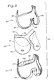
- Fig. 7 is a perspective view of an assembled prosthetic heart valve of the present invention.
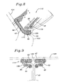
- Fig. 8 is a cross-sectional view through a cusp of the prosthetic heart valve of the present invention, taken along line 8-8 of Fig. 7 , and showing a portion of the host annulus in phantom;
- Fig. 9 is a cross-sectional view through a commissure of the prosthetic heart valve of the present invention, taken along line 9-9 of Fig. 7 , and showing a portion of the host aortic wall in phantom;
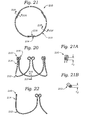
- Fig. 10 is a sectional view of the exemplary prosthetic heart valve of figure 7 shown implanted in an aortic annulus;
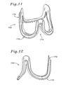
- Fig. 11 is a perspective view of an alternative connecting band for use with a flexible heart valve of the present invention.
- Fig. 12 is a left side elevational view of the connecting band of Fig. 11 ;
- Fig. 13 is a top plan view of the connecting band of Fig. 11 ;
- Fig. 14 is a rear elevational view of the connecting band of Fig. 11 ;
- Fig. 15 is a front elevational view of the connecting band of Fig. 11 ;
- Fig. 16 is a bottom plan view of the connecting band of Fig. 11 ;
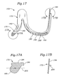
- Fig. 17 is a sectional view of the connecting band of Fig. 11 taken along line 17-17 of Fig. 13 and illustrating preferred cross-sectional shapes at both the cusps and commissures;
- Figs. 17A and 17B are enlarged cross-section sectional views of the connecting band of Fig. 17 ;
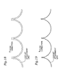
- Fig. 18 schematically illustrates an intra-sinular suture placement relative to a solid leaflet attachment line
- Fig. 19 schematically illustrates a preferred supra-annular suture placement relative to a solid leaflet attachment line
- Fig. 20 is a side elevational view of an exemplary stress-absorbing heart valve support frame of the present invention.
- Fig. 21 is a top plan view of the heart valve support frame of Fig. 20 ;
- Fig. 22 is a diametric sectional view of the exemplary heart valve support frame of Fig. 20 taken along line 22-22;
- Fig. 23 is an enlarged elevational view of a tip of a commissure of the exemplary heart valve support frame of the present invention.
- Fig. 24 is an enlarged elevational view of a tip of a commissure of a heart valve support frame of the prior art
- Fig. 25 is a graph of the circumferential thickness of the commissure region of the exemplary heart valve support frame with graph points corresponding to those indicated in Fig. 24 ;
- Fig. 26 is a graph of strain versus position for the two support frame commissures shown in Figs. 23 and 24 with graph points corresponding to those indicated on the figures.
- the present invention provides a sewing ring or connecting band for a highly flexible aortic heart valve that is attached generally along a scalloped or undulating perimeter downstream from where the natural leaflets were originally attached.
- the natural leaflets include arcuate cusp portions separated by common commissure portions. If the natural valve has three leaflets, and has a vertically oriented flow axis, the leaflets are evenly distributed circumferentially 120° apart with lower (upstream) cusp portions and upper (downstream) generally axially aligned commissure portions.
- the annular root of the native aortic valve is composed of fibrous tissue and generally conforms to the undulating perimeter of the valve to support the leaflets.
- implanting a prosthetic aortic heart valve of the present invention involves typically excising the natural leaflets and then attaching the prosthetic heart valve proximate the fibrous annulus.
- Certain embodiments may be attached a short distance up the aortic wall, although attachment entirely to the fibrous annulus may be preferred.
- Various attachment means may be used, including sutures, staples, adhesives, or other similar expedients.
- Figs. 1 and 2 illustrate the two phases of left ventricular function, systole and diastole.
- Systole refers to the contraction or pumping phase of the left ventricle when the aortic valve opens
- diastole refers to the expansion or filling phase during which the aortic valve is closed.
- Figs. 1 and 2 illustrate in cross-section the left chamber of the heart with the left ventricle 20 at the bottom, and the ascending aorta 22 and left atrium 24 diverging upward from the ventricle to the left and right, respectively.
- Fig. 1 illustrates systole with the left ventricle 20 contracting
- Fig. 2 illustrates diastole with the left ventricle dilating.
- the aortic valve 28 is schematically illustrated here as having leaflets 30.
- the native aortic valve has a tri-leaflet structure.
- Contraction of the ventricle 20 causes the mitral valve 26 to close and the aortic valve 28 to open, and ejects blood through the ascending aorta 22 to the body's circulatory system, as indicated in Fig. 1 by the arrows 32.
- Dilation of the ventricle 20 causes the aortic valve 28 to close and mitral valve 26 to open, and draws blood into the ventricle from the left atrium 24, as indicated in Fig. 2 by the arrows 33.
- the walls of the left chamber of the heart around the aortic valve can be generally termed the annulus region 34 and the sinus region 36.
- the annulus region 34 defines an orifice that is the narrowest portion between the ventricle 20 and ascending aorta 22, which as noted above is composed of fibrous tissue.
- the sinus region 36 is that area just downstream (up in the drawing) from the annulus region 34 and includes somewhat more elastic, less fibrous tissue.
- the sinus region 36 typically includes three identifiable, generally concave sinuses (formally known as Sinuses of Valsalva) in the aortic wall intermediate the upstanding commissures of the valve 28. The placement of the sinuses corresponds to the location around the annulus periphery of the three leaflets.
- the sinuses are relatively elastic and are constrained by the intermediate, more fibrous commissures of the aortic annulus. That is, the annulus region 34 and sinus region 36 are not discretely separated into either fibrous or elastic tissue, as the fibrous annulus extends a short distance axially into the sinus region 36 at the three commissures.
- the sinuses tend to move in and out to facilitate fluid dynamics of the blood in conjunction with systole and diastole.
- the sinus region 36 expands somewhat to a diameter A. This facilitates blood flow through the ascending aorta 22 to the rest of the body.
- the sinus region 36 contracts somewhat to a smaller diameter B and help close the three leaflets.
- the diameters A and B are intended to be a measurement of the radial movement of the commissure regions of the valve 28.
- the sinus region 36 has a neutral, or relaxed diameter (not shown) somewhere in between diameters A and B.
- the annular region 34 also moves in and out during the systolic and diastolic phases. As seen in Fig. 1 , the annular region 34 contracts somewhat to a diameter C during systole. In contrast, during the diastolic phase as seen in Fig. 2 , the annular region 34 expands somewhat to a larger diameter D. Much like the sinus region 36, the annular region 34 has a neutral, or relaxed diameter (not shown) somewhere in between diameters C and D.
- a highly flexible prosthetic valve of the present invention accommodates the in-and-out movements of both the annular region 34 and the sinus region 36. That is, alternating peripheral portions of the prosthetic valve are attached to the annular region 34 and the sinus region 36, or adjacent thereto, and move accordingly. It is important to point out that the preceding discussion of dynamic movement of the annulus and sinus regions is based on preliminary understanding of such movement. That is, direct measurements of these movements are problematic, and thus certain assumptions and predictions must be made. The actual dynamic movement in any particular human heart may be different, but the principles of the present invention would still apply. Certainly, relative movement in the annulus and sinus regions during systole and diastole does exist, and the highly flexible prosthetic heart valve of the present invention accommodates such movement.
- Fig. 3 the primary sub-assemblies of a preferred embodiment of a flexible prosthetic heart valve 40 having a connecting band 42 of the present invention are shown in exploded view.
- the directions up and down, upper and lower, or top and bottom, are used with reference to Fig. 3 , but of course the valve can be oriented in any direction both prior to and after implantation.
- the heart valve 40 comprises a stent assembly 44, a group 46 of three leaflets 48a, 48b, 48c, and the connecting band 42.
- Each of the sub-assemblies seen in Fig. 3 is procured and assembled separately (except for the group of leaflets, as explained in U.S. Patent No. 6,558,418 ), and then joined with the other sub-assemblies to form the fully assembled valve 40 as seen in Fig. 7 .
- the prosthetic valve 40 is a trifoliate valve with three leaflets 48a, 48b, 48c. Although three leaflets are preferred, and mimic the natural aortic valve, the principles of the present invention can be applied to the construction of a prosthetic valve with two or more leaflets, depending on the need.
- Each of the sub-assemblies seen in Fig. 3 includes three cusps separated by three commissures.
- the leaflets 48 each include an arcuate lower cusp edge 50 terminating in upstanding commissure edges 52.
- Each leaflet 48 includes a coapting or free edge 54 opposite the cusp edge 50.
- the stent assembly 44 also includes three cusps 60 separated by three upstanding commissures 62.
- the connecting band 42 includes three cusp portions 64 separated by three upstanding commissure portions 66.
- an inner stent 70 of a preferred stent assembly 44 is seen in Fig. 4 .
- the stent assembly 44 also comprises an outer cloth cover as shown in Fig. 3 .
- the inner stent 70 may comprise three identical and separate stent members, each of which has a separate cloth covering.
- the inner stent 70 desirably comprises a single element generally circumscribing a tube with an undulating shape defined by alternating inflow cusp regions 72 and outflow commissure regions 74.
- the arcuate cusp regions 72 have large radii of curvatures relative to the upstanding commissure regions 74, each of which terminate at a tip 76.
- the inner stent 70 preferably comprises an elongated rod- or wire-like member made out of an elastic biocompatible metal and/or plastic alloy, such as Elgiloy®, Nitinol, polypropylene, etc.
- the stent 70 may be bent into the illustrated shape, using conventional wire-forming techniques.
- the material selected for the inner stent 70 should be elastic to permit flexing along their lengths, but should possess a minimum of stiffness to avoid asymmetric deformation of the constructed valve 40.
- the stent 70 supplies an inner frame for the valve 40 that is relatively more rigid than the other components. Therefore, the stent 70 acts to limit total flexibility of the valve 40.
- the stent 70 comprises a single element of Nitinol that is originally severed in a predetermined pattern from a flat sheet and then be formed into the three-dimensional shape shown.
- the formation method may include heat setting, one example of which is provided in U.S. Patent Application Document No. 2004/0078950 .
- the resulting structure has a rectilinear cross-section, which is desirably electropolished to remove sharp edges.
- each commissure tip 76 includes a pair of nearly circular outer flexure portions 78 connected by an oppositely-curved inner bridge portion 80.
- the flexure portions 78 project in the outflow direction, while the bridge portion 80 projects in the inflow direction.
- the resulting shape resembles mouse ears in that there are two relatively large convex portions joined by a concave bridge.
- the flexure portions 78 each possess a relatively large radius of curvature relative to the spacing and nearly 360° change of direction between adjacent commissure regions 74.
- the flexure portions 78 enhance the ability of the cusp regions 72 of the stent 70 to move with respect to one another.
- the cross-sectional shape and size of the flexure portions 78 may be designed to further enhance the flexibility of the stent 70.
- a portion of the tips 76 may be designed to break after certain number of movement cycles of the stent 70, so that the structural support within the valve 40 separates into individual cusps.
- a portion of the tips 76 such as the bridge portions 80, may be designed to break after certain number of movement cycles of the stent 70, so that the structural support within the valve 40 separates into individual cusps.
- the material for the stent 70 may be highly flexible so as to add relatively little reinforcement to the valve 40.
- the inner stent 70 may be formed of a length of medical grade silicone that provides some physical structure that helps in stitching fabric around the valve, and also helps provide some bulk for grasping and sewing the valve in place, but otherwise does not reduce the flexibility of the other components.
- the commissures 76 are inherently flexible, enabling the cusp regions 72 to flex or pivot with respect to one another. This very high flexibility of the valve 40 minimizes any unwanted impediment to the natural annulus and aortic wall movement, and desirably maximizes the flow orifice formed though the valve, thus reducing any pressure loss therethrough.
- the highly flexible stent material may be provided in one or multiple filaments, with or without a surrounding enclosing sleeve, and may be silicone as mentioned, polypropylene, Delrin®, polyurethane, polytetrafluoroethylene (PTFE), or the like.
- An exemplary thickness of the highly flexible stent material is about 0,28-0,33 mm (0.011-0.013 inches) for a monofilament version, or up to 0,64 (0.025 inches) with multiple filaments.
- Each of the commissure tips 76 is positioned slightly radially inward with respect to the arcuate cusp regions 72.
- a gradual radially outward bend 82 is provided in the stent 70 at a transition between each of the commissure regions 74 and the intermediate cusp region 72. This bend 82 permits the inner stent 70 to remain in a tubular configuration. That is, if the cusp regions 72 extended in a plane between each of the commissure regions 74, the plan view would be somewhat polygonal. Instead, each of the cusp regions 72 includes a lower apex, and the apices of all of the cusps define a circle concentric with and having the same diameter as a circle defined by all of the tips 76.
- the stent 70 thus defines a substantially cylindrical volume therewithin.
- other volumes may be defined by the stent 70 wherein the tips 76 define a circle that is smaller or larger than a circle defined by the apices.
- the apices may be provided outward from the tips 76 so the stent 70 defines a frusto-conical volume therewithin.
- the inner stent 70 is preferably covered with a generally tubular cloth.
- the cloth cover is a biocompatible fabric, such as polyethylene terephthalate, and includes a tubular portion closely conforming around the inner stent 70 and a flap 86 extending radially outward therefrom.
- the cloth cover is formed by wrapping an elongated sheet of fabric around the inner stent 70 and joining the free edges with sutures to form the flaps 86.
- the flap 86 extends from the stent 70 in a direction that is generally outward with respect to the cusp region 72, and continues in the same general orientation up the commissure regions 74 to the tips 76.
- the stent assembly 44 provides an inner support frame that is generally rigid along the cusp regions 72 of the inner stent 70, but which permits the cusp regions to move with respect to one another.
- “generally rigid” refers to the structural strength of the inner stent 70 that is sufficient to maintain the general shape, especially during delivery and implant, but that permits some flexing at the commissure regions 74.
- the inner stent 70 provides nodes or pivot points of the valve 40 at the commissures 62 of the stent assembly 44. Because of these nodes, the cusp regions 72 are permitted to move radially inward and outward with the motion of the surrounding anatomy. Inward pivoting is permitted by spaces 88, seen in Fig. 4 , defined between adjacent commissure regions 74 of the inner stent 70. These regions 88 are generally triangular and gradually increase in size from the attached commissure tips 76 to the diverging cusp regions 72.
- Figs. 3 , 5 and 6 illustrate in more detail the connecting band 42 that comprises an inner member 90 surrounded by a cloth cover 92 (shown partially cutaway in the figures).
- the connecting band 42 includes cusp portions 64 alternating with commissure portions 66.
- the continuous undulating connecting band 42 mirrors the shape of the stent assembly 44, generally circumscribing a tube and having an undulating shape with three cusp portions 64 alternating with three commissure portions 66, the cusps having large radii of curvatures relative to the commissures. This shape is provided by the inner member 90, with the cloth cover 92 closely wrapped therearound and sewn closed.
- the inner member 90 is a suture-permeable material such as molded silicone rubber, and the cloth cover 92 is polyethylene terephthalate. While the stent assembly 44 provides structural support for the leaflets 48, the connecting band 42 supplies an interface between the prosthetic valve 40 and the surrounding anatomy such that sutures or staples may be used for implantation.
- suture-permeable refers to materials that may be punctured not just with sutures but also with staples and the like.
- the inner member 90 has a varying cross-sectional shape from cusp portion to commissure portion.
- Fig. 5A is cross-section through one of the cusp portions 64 of the connecting band 42, and shows a region of the inner member 90 having an inner ledge 94 and upwardly angled outer flap or free margin 96.
- the cloth-covered ledges 94 extend generally radially inward and define three stent supports 98 of the connecting band 42, as seen in Fig. 6 .
- the ledge 94 has its greatest radial dimension at the midpoint or apex of each of the cusp portions 64 and gradually tapers down in size toward the commissure portions 66.
- the free margins 96 form their greatest outward angle with respect to a central axis of the connecting band 42 at each cusp portion 64, and gradually re-align to be parallel to the central axis in the commissure portions 66.
- the cross-section of the inner member 90 at the commissure portions 66 is seen in Fig. 9 .
- the commissure portions 66 of the connecting band 42 define generally axial gaps 100 that help permit flexing of the valve 40.
- the connecting band 42 may be discontinuous at the commissure portions 66 if the valve has bioresorbable commissures and is designed to separate into individual "leaflets.”
- Fig. 3 illustrates an exemplary arrangement of generally radial cuts or slits 102 formed in the free margins 96 of each of the cusps of the inner member 90.
- the slits 102 extend from the outflow edge of the free margin 96 to a maximum length terminating at a corner between the free margin 96 and the radial ledge 94 (see Fig. 5A ).
- the slits 102 open to the inside radius of the curvature of each cusp region 64, they provide the relief points within the material of the inner member 90 along that edge and facilitate spreading apart of the commissure regions 66 of the connecting band 42 during flexing of the prosthetic valve 40.
- the weave or construction of the cloth covering 92 on the connecting band may have greater elasticity in the circumferential direction than in the radial direction around the cusp regions 64.
- Fig. 6 also illustrates a sub-assembly 110 in which the leaflets 48 are secured to the stent assembly 44
- Fig. 7 illustrates the assembled valve 40 in perspective
- Figs. 8 and 9 show cross-sections through a valve cusp 112 and valve commissure 114, respectively.
- the peripheral shape of the valve 40 defined by the combined stent assembly 44 and connecting band 42, generally circumscribes a tube and has an undulating shape with alternating inflow cusps 112 and outflow commissures 114, and the leaflets extend inward therefrom to provide flexible flow occluding surfaces.
- the leaflets 48 are pre-attached to align the free edges 54 ( Fig. 3 ).
- the free edges 54 of each two adjacent leaflets 48 extend outward in juxtaposition and are received within the triangular space 88 ( Fig. 3 ) defined between the commissure regions 74 of the stent assembly 44.
- the group of assembled leaflets 46 is thus "inserted” underneath the stent assembly 44 until the juxtaposed free edges 54 of the leaflets 48 are in close proximity below the cloth-covered tips 76 of the stent.
- An outer margin 116 of each leaflet 48 is folded underneath the corresponding cusp 60 of the stent assembly 44.
- the sandwiched configuration of the stent assembly 44, leaflet 48, and connecting band 42 can be seen.
- the connecting band 42 is sewn or otherwise attached to the exterior of the stent/leaflet subassembly 110 ( Fig. 6 ).
- the connecting band 42 is attached underneath the stent/leaflet subassembly 110 at the cusps, but the free margins 96 of the connecting band are positioned to the outside of the subassembly.
- the cloth flap 86 of the stent assembly 44 aligns with the leaflet margins 116, which in turn rest on the stent supports 98.
- a series of suture stitches 120 are used to secure these elements together.
- the flap 86 terminates at the same location as the margin 116 of each leaflet 48, and at the corner defined in the connecting band 42 between each ledge 94 and free margin 96.
- the radially innermost wall of the ledge 94 is preferably inward from or at least axially below the stent 70. This supporting construction helps prevent the stent 70 from migrating downward with respect to the connecting band 42.
- the host annulus 122 is seen in phantom with the aortic wall 124 continuing upward therefrom. It can be readily seen that the angled shape of the cusp portions 64 of the connecting band 42 conform nicely to the host annulus and adjacent sinular region.
- FIG. 9 shows the assembly of the valve components in the commissure region.
- the commissure edges 52 of each of the leaflets 48 are sandwiched in between the stent assembly 44 and connecting band 42. More particularly, the commissure edges 52 are sandwiched between the flaps 86 and the generally planar commissure portions 66 of the connecting band 42 ( Fig. 6 ). Sutures 126 are provided to join these elements together.
- the commissure edges 52 preferably terminate at the same location as the flaps 86.
- Fig. 9 shows in phantom a portion of the aortic wall 128 to which the commissures 114 of the valve 40 are attached. Again, the particular attachment means is not shown, but the connecting band 42 is traditionally sutured to the wall 128.
- Fig. 9 also illustrates the gap 100 provided in the commissure regions of the connecting band 42, and the lack of structural connection between the two sides of each valve commissure 114.
- the prosthetic valve 40 exhibits three gaps 130 at the commissures 114 that provide the desired flexibility.
- the gaps 130 are created by the gaps 88 in the stent assembly 44 and the gaps 100 in the connecting band 42.
- the gaps 130 preferably extend a majority of the height of the valve from an inflow and at the lowest apex of the cusps 112 into close proximity with the commissure tips.
- the gaps 130 extend at least about 50% of the entire height of the valve to enable the cusps 112 to move with respect to one another, preferably between about 55-75%, and more preferably about 65%.
- the prosthetic heart valve 40 of Figs. 3-9 is particularly suitable for intra-sinular placement in the aortic position. That is, the cusps 112 are typically positioned just to the outflow side of the aortic annulus, while the commissures 114 extend up above the native commissures to the aortic wall, in the region of the sinuses.
- Fig. 18 is a schematic illustration of this implant scheme, with the solid line depicting a flattened undulating native leaflet attachment line, and the row of Xs indicating the intra-sinular placement of sutures or staples to attach a prosthetic valve.
- the suture line is positioned slightly to the outflow side of the annulus, potentially within the weaker tissue of the wall of the ascending aorta.
- Some surgeons express concern about possible aortic damage from attaching the connecting band 42 of the valve 40 of Figs. 3-9 to the aortic wall, as opposed to the fibrous annular tissue.
- the valve 40 would end up in an intra-annular position because of the enlarged free margin 96 of the connecting band 42.
- intra-annular position refers to the location within the inwardly projecting annulus.
- This position has been the conventional implant location for more rigid heart valves, which, as mentioned above, tends to reduce the orifice size and thus the blood flow therethrough.
- opinions vary, there is a need for a highly flexible prosthetic heart valve that can be attached entirely to the annulus in a "supra-annular" position.
- the term "supra-annular position” refers to a location just downstream from the inwardly projecting annulus, along the line that the native leaflets attach.
- the present invention provides an alternative prosthetic valve 150 seen implanted in a supra-annular position in Fig. 10 that incorporates a connecting band 152 seen in Figs. 11-17 .
- the prosthetic valve 150 is constructed in the same manner as the prosthetic valve 40 of Figs. 3-9 , with the substitution of the alternative connecting band 152 for the earlier-described band 42.
- the region of the heart depicted shows the left ventricle LV at the bottom separated from the ascending aorta AA at the top by the aortic annulus 160.
- the aortic annulus 160 is primarily defined by fibrous tissue that forms an inwardly projecting ledge 162 at the cusps and upwardly projecting commissures 164.
- the shape of the annulus 160 is undulating with three cusps 162 curved in the inflow direction alternating with three commissures 164 projecting in the outflow direction.
- the fibrous tissue is cross-hatched differently than the adjacent tissue, although anatomists will understand that there is not always such a clear dividing line between the fibrous and non-fibrous tissues.
- the prosthetic heart valve 150 includes alternating cusps 154 and commissures 156 that conform to the native aortic annulus 160. A number of suture stitches 156 are shown attaching the valve 150 to the annulus 160. In a preferred embodiment, standard suture techniques may be used to implant the valve 150 in the supra-annular position as shown. That is, the entire valve 150 attaches to the fibrous tissue defined by the aortic annulus 160, as opposed to continuing up the wall of the ascending aorta AA. Because of the supra-annular positioning, the valve 150 can be sized larger than conventional valves that fit within the annulus, or in an intra-annular position.
- the size of the orifice defined by the annulus 160 is not unduly constricted. Furthermore, the flexibility of the valve 150 and attachment up the commissures 164 enables it to match the reciprocating motions of the different parts of the annulus 160, as was described with respect to Figs. 1 and 2 .
- Fig. 19 schematically illustrates a preferred supra-annular suture placement relative to a solid leaflet attachment line.
- the Xs indicate placement of sutures or staples to attach the prosthetic valve 150. Because the line of sutures corresponds to the line of native leaflet attachment, none of the sutures extends into the tissue of the ascending aorta.
- the alternative connecting band 152 provides features that permit supra-annular suture placement and which will maintain the position of the prosthetic valve 150 without allowing it to slide into an intra-annular position. Finally, the connecting band 152 remains highly flexible such that the resulting valve 150 accommodates relative movement of the adjacent annulus and sinuses.
- the alternative connecting band 152 includes the familiar alternating cusp 170 and commissure 172 shape. Indeed, the overall undulating shape of the connecting band 152 is much like the connecting band 42 seen in Fig. 3 .
- generally axially-oriented gaps 174 are again defined between the cusps 172 enabling flexing of the valve 150 once implanted.
- the height h of each of the gaps 174 is preferably at least about 50%, preferably between about 55%-75%, of the entire axial height H of the connecting band 152, and a ratio of about 65%, is most desirable.
- gap ratios (h/H) may differ depending on the size of valve. Specific examples are: 59% for 19mm valves, 64% for 23mm valves, and 69% for 29mm valves.
- a preferred configuration of the connecting band 152 which includes radially thick cusps 170 separated by radially thin commissures 172.
- the cross-section 17A is taken through the apex of one of the cusps 170 and also through one of a plurality of radial ribs 180 separated by grooves 182 provided on the inflow side thereof.
- the bottom plan view of the connecting band 152 of Fig. 16 illustrates the circumferential spacing of these radial ribs 180, while various views show their relative size and contours.
- the apex of the cusp 170 includes a flat upper or outflow surface 184 that extends inward to a lip 186.
- the shape of the radial ribs 180 includes a radially outwardly angled projection or lobe 188 that defines the inflow end of the connecting band 152. As seen best in Fig. 16 , the size of the radial ribs 180 gradually diminishes from the apex toward each adjacent commissures 172. Fig. 17 illustrates the distance to which the ribs 180 extend toward the commissures 172. Essentially, the ribs 180 are provided in the portion of the cusps 170 that extends along a gradual curve at the inflow end, and they terminate at a point at which the connecting band 152 exhibits a marked curvature toward the axial direction, continuing to the commissures 172.
- Fig. 17 also illustrates the transition between the apex of the cusps 170 and the commissures 172.
- the connecting band 152 is primarily oriented in a radial direction at the cusp apex, but it has a substantially axial component in the commissures 172.
- the outflow surface 184 and the cusp apex is defined by a radially inward shoulder or ledge 190 that gradually disappears toward each commissure 172.
- an outwardly directed flap or free margin 192 which is not present at the cusp apex, commences on both sides of the cusp apex and increases in size toward each commissure 172.
- the free margin 192 projects radially outward and in the outflow direction, much like the free margin 96 seen in Fig. 5A .
- the free margin 192 then transitions from the outwardly angled orientation to a substantially axially-oriented free margin 194 at the commissures 172.
- Fig. 17B depicts the shape and slightly outwardly angled orientation of the free margin 194 at the commissures.
- the illustrated free margin 192, 194 gradually diminishes in size from each commissure 172 to an apex of each cusp 170, the free margin may also remain a constant radial width around the periphery of the connecting band 152.
- the ledge 190 functions to receive a stent/leaflet sub-assembly, such as that shown at 110 in Fig. 6 .
- the ledge 190 prevents the stent/leaflet sub-assembly from migrating downward with respect to the connecting band 152. That is, the greatest axial forces experienced by the implanted valve, at least in the aortic position, are generated during diastole when the left ventricle fills and the aortic leaflets close. High pressure within the ascending aorta and reduced pressure in the left ventricle imparts an axial force in the inflow direction to the prosthetic valve.
- the entire valve assembly maintains its integrity over time.
- the connecting band 152 also features an outwardly-directed reinforcing flange 200 in the middle of and tracing the shape of the commissures 172. That is, the reinforcing flange 200 has an inverted U-shape.
- the free margin 194 at the commissures 172 projects axially and circumferentially beyond the reinforcing flange 200 as shown.
- the outwardly-directed lobe 188 at the cusps 170 and the reinforcing flange 200 form a continuous undulating reinforcing ridge or bulge around the periphery of the connecting band 152.
- this continuous ridge provides sufficient mass within the connecting band 152 to permit the supra-annular placement with annular suture techniques. That is, in contrast with earlier connecting bands, such as the band 42 of Figs. 3-9 , the connecting band 152 provides a sewing ridge on its inflow side that the surgeon can feel and grasp and pass sutures through using the annular suture technique.
- the ridge is most prominent at the midpoint of the cusps 170 corresponding to the native annulus cusps, but also extends up the commissures 172 as the reinforcing flange 200 which can be sewn to the upstanding fibrous commissures, as seen in Fig. 10 .
- the connecting band 152 remains highly flexible and avoids unduly limiting the correspondent motion of a flexible heart valve made therewith.
- radial slots were provided around the cusps to enhance their flexibility.
- the sewing ridge is discontinuous at the cusps and continuous at the commissures.
- the connecting band 152 provides the grooves 182 in between each of the radial ribs 180 on the inflow side of the cusps 170. These grooves provide relief points that improve the compliance of the connecting band 152 without sacrificing the beneficial sewing ridge provided by the intermittent ribs 180.
- each cusp 170 has a varying cross-section between adjacent commissures 172 that includes at least one relief point (slits 102 or grooves 182) at which the cross-section abruptly reduces such that bending of the connecting band cusps occurs first at the relief point.
- the aforementioned free margin 192 decreases to nothing at the apex of each cusp 170, as seen in Fig. 17A .
- this reduction in the free margin 192 greatly enhances the necessary flexibility of the cusps 170.
- each cusp 170 has a radial cross-section that gradually diminishes in area moment of inertia relative to a bending plane 202 ( Fig. 17A ) that extends perpendicular to the flow axis of the connecting band 152.
- the sewing ridge (comprising the outwardly-directed lobe 188 and reinforcing flange 200) gradually increases in size from the end of each commissure 172 to an apex of each cusp 170, the sewing ridge may also exhibit a constant radial width around the periphery of the connecting band 152.
- the important point is that the sewing ridge is large enough for ease-of-use for surgeons to pass a suture through, and as small as possible to minimize bulk in the flow tract. Also it should be large enough and compliant enough to fit in the native anatomy without leaking.
- the cusp area is larger to allow it to be more adaptable at the base where removal of calcified leaflets and surrounding calcification often leaves a ragged edge.
- the exemplary inner stent 70 of Fig. 4 is shown in greater detail in figures 20-23 , and will be referred to hereinafter as a heart valve support frame 210.
- the heart valve support frame 210 desirably comprises a single element generally describing a tube with an undulating shape defined by alternating inflow cusp regions 212 and outflow commissure regions 214.
- the arcuate cusp regions 212 have large radii of curvatures relative to the upstanding commissure regions 214, each of which terminate at a tip 216.
- the heart valve support frame 210 comprises an elongated rod- or wire-like member made out of an elastic biocompatible metal and/or plastic alloy, such as Elgiloy®, Nitinol, polypropylene, etc.
- the support frame 210 is formed by cutting a two-dimensional blank from a sheet of Nitinol and subsequently bending and heat setting the blank into a three-dimensional support frame, as disclosed in co-pending U.S. Patent Application Document No. 2004/0078950 .
- Fig. 21A is a radial sectional view through one of the commissure tips 216
- Fig. 21B is a radial sectional view through one of the cusp regions 212.
- These views are essentially enlargements of the terminal ends of the sectional view of Fig. 22 .
- the cross-sectional shape of the wire-like member is thus shown as a rectangle with rounded corners which results from cutting the blank from the sheet of Nitinol, forming it into a three-dimensional support frame, and then electropolishing the support frame.
- the support frame 210 has a varying cross-section with a maximum located at the commissure tips 216.
- 21A and 21B are the same and correspond generally to the thickness of the original sheet of Nitinol.
- the vertical dimension or thicknesses t 1 and t 2 may vary based on the particular shape cut into the Nitinol sheet. Ideally, this cutting is done by laser.
- each commissure tip 216 includes a pair of nearly circular outer flexure portions 218 connected by an oppositely-curved inner bridge portion 220.
- the flexure portions 218 project in the outflow direction, while the bridge portion 220 projects in the inflow direction.
- the resulting shape resembles mouse ears.
- the flexure portions 218 each possess a relatively large radius of curvature relative to the bridge portion 220, and a nearly 360° change of direction between adjacent commissure regions 214.
- Fig. 23 Various discrete points are indicated on Fig. 23 to help identify the contours of the commissure regions 214 and commissure tips 216.
- point A corresponds generally to a transition between the adjacent cusp regions 212 (see figure 20 ) and the substantially vertical commissure regions 214.
- point B represents the end of the generally vertical commissure regions 214 and the beginning of the commissure tip 216.
- point C corresponds to the beginning of one of the substantially circular flexure portions 218.
- Point D is located in the middle of the left flexure portion 218.
- Point E represents the termination of the flexure portion 218 leading to the bridge portion 220, corresponding to point F.
- Fig. 25 is a graph of the thickness in inches of the points indicated around the commissure regions 214 and commissure tip 216 in Fig. 23 .
- the thickest point is at D in the middle of the flexure portions 218, while the thinnest point is at A at the lower part of the commissure regions 214.
- Both the bridge portion 220 and the curves 222 have a smaller thickness than the flexure portions 218.
- Point B at the top of each commissure region 214 is larger than point A at the bottom, with a gradual taper therebetween.
- the flexure portions 218 and the varying thicknesses enhance the ability of the cusp regions 212 of the support frame 210 to move with respect to one another. That is, the larger bend radius of the flexure portions 218 provided at the commissure tips 216 relative to a simple inverted U-shape, as in a conventional heart support stent, such as seen in Fig. 24 , provides a longer moment arm between the ends of the adjacent commissure regions 214. That is, the distance around the wire-like member of the support frame 210 between the upper ends of the adjacent commissure regions 214 (point B) is significantly greater than the distance between the same points in the support frame of the prior art, as seen in Fig. 24 .
- the complex curve as shown better distributes the forces to provide a stress-absorbing structure that greatly reduces the possibility of fatigue failure.
- the complex curve can be described relative to an observer on the outside of each of the commissure tip 216.
- the outward curves 222 are concave
- the flexure portions 218 are convex
- the bridge portion 220 is concave again.
- two oppositely directed arrows indicate the general direction of a bending moment M experienced by the support frame 210 in use. This bending moment M acts on the adjacent commissure regions 214 and pulls them apart.
- the bending moment M tends to close or reduce the radius of curvature of both the bridge portion 220 and outward curves 222, while opening or increasing the radius of curvature of the flexure portions 218.
- Fig. 24 indicates a commissure tip of a support frame of the prior art that is shaped substantially as an inverted U.
- Point G indicates the smallest radius of the substantially convex commissure tip at which the greatest stress occurs.
- Fig. 26 shows the stress generated around the commissure tip from the midpoint thereof around to the commissure region. There is a stress riser at point G which is undesirable given the extreme conditions under which the support frame operates. In other words, such a stress concentration point will be more likely to fail from fatigue after millions of cycles within the heart.
- Fig. 23 indicates the smallest gap X between the upper ends of the two converging commissure regions 214, substantially corresponding to point B on both sides.
- the same gap X is seen in Fig. 24 for the commissure tip of the prior art.
- the simple inverted U-shape of the commissure tip of the prior art results in a distance around the tip that can be estimated as ⁇ X the distance around a circle having a diameter of X. (Although there is not a complete circle around the commissure tip, the tip actually expands slightly from the gap between the commissure regions and forms a 3 ⁇ 4 circle having a diameter slightly larger than X).
- a simple semi-circle or inverted U-shape at the top of the commissure regions would result in a distance around the commissure tip of ⁇ X/2. Therefore, a good approximation of the distance around a simple commissure tip of the prior art is between 1.6X-3.2X, with X being the smallest gap between the upper ends of the two converging commissure regions.
- the distance around the commissure tip 216 of the support frame 210 of the present invention is substantially longer. That is, the total length in which the bend occurs around the commissure tips 216 is increase without substantially increasing the overall size of the support frame 210, and without overlapping the material which would lead to a more radially bulky structure.
- the two flexure portions 218 themselves represent near circles having diameters slightly larger than the gap X, resulting in a distance of at least 2 ⁇ X.
- the present invention provides a commissure tip having a distance therearound which is greater than 6X, where X is the closest distance between the upper ends of the adjacent commissure regions.
- the present invention contemplates any number of non-overlapping complex curves which reduce the stress at the commissure tips.
- an "overlapping" curve is one which coils or otherwise winds over itself at least once, such as does a coil spring.
- Those of skill in the art will understand that even a simple enlarged bulbous head at the top of the commissure tip will reduce the stress concentration relative to the shape seen in Fig. 24 .
- the stress-absorbing support stent of the present invention has commissure tips of various shapes with lengths greater than 6X, where X is the closest distance between the upper ends of the adjacent commissure regions.
- the stress-absorbing capabilities of the support frame 210 are optimized by varying the cross-sectional thickness therearound.
- the circumferential dimension varies around the frame as indicated in the graph of Fig. 25 .
- the points A-F located on the curve correspond to the same points around the commissure tip 216 identified in Fig. 23 .
- the "position" S starts at a midpoint of the commissure tip 216 as indicated by the directional legend at the top of Fig. 24 for the prior art commissure tip. That is, point F at the left side of the graph of Fig. 25 corresponds to the bridge portion 220, while point A corresponds to the commissure region 214.
- the circumferential dimension is greatest at point D, which is within the flexure portion 218.
- the cross-section of the flexure portions 218 is greater than the bridge portion 220 (point F), and also greater than the curve 222 between the flexure portion 218 and the commissure region 214.
- the top of the commissure region 214 at point B is wider than the bottom, as indicated by the downward slope from point B to point A on the graph of Fig. 25 .
- the commissure regions 214 gradually taper more narrow toward the arcuate cusp regions 212.
- the exemplary commissure tips 216 will help reduce the stresses associated with repetitive bending loads on the support frame, and therefore reduce instances of failure and increase the life of the support frame.
- the commissure tips 216 are shaped in the manner illustrated in Fig. 23 such that the flexure regions 218 greatly increase the non-overlapping length of the wire-like elements between the adjacent commissure regions 214. This, in itself, helps reduce stresses associated with otherwise narrow curvature.
- the exemplary shape illustrated with two flexure regions 218 separated by a bridge portion 220 spreads the bending stresses out over relatively large convexities and a central concavity (as viewed from the outflow end).
- the aforementioned variance of the cross-section around the commissure tip 216 even further helps reduce the instance of failure.
- a single convex curve i.e., bulbous shape
- the simple inverted U-shape as seen in the prior art commissure tip of Fig. 24
- the maximum diameter of a commissure tip 216 to avoid these issues is desirably about 3 mm.
- the commissure tips 216 are desirably non-overlapping so that they present only a single radial thickness which accordingly minimizes the radial size of a finally constructed valve.
- the present support frame 210 was designed to allow for physiologic motion while minimizing stresses and optimizing fatigue life. In the development of the shape and size of the support frame 210, physiologic motions were analyzed and worst-case assumptions were determined. The strains in a physiologic environment determined the minimum stress requirements of the design. The final shape shown in Fig. 23 provides a maximum radii of curvature of the flexure portions 218 while maintaining the anatomical constraints of the aorta, the implant concerns of the surgeon, and manufacturing constraints.
- the risk of fracture was reduced by changing the shape of the commissure tips to redistribute the strains evenly.
- the thickness of the support frame was reduced from previous designs. A point of inflection between the two flexure regions 218 was added at the bridge portion 220. In regions (i.e., flexure portions 218) where the radius of curvature is opened by the applied moment (M in Fig. 24 ) the radius of curvature and the thickness are increased. In the regions (i.e., bridge portion 220 and curve 222) where the radius of curvature is closed by the applied moment M the radius of curvature and the thickness are decreased.
- the strains associated with bending of the commissure tips shown in Figs. 23 and 24 are shown.
- the relatively flat curve represents the strain induced in the commissure tips 216 of the present invention with the points A-E corresponding to the same points shown in Fig. 23 .
- the strain curve of the commissure tip of the prior art has a peak at point G located at the smallest curvature of the simple U-shape.
- repeated stressing of such a design may result in failure at the stress concentration.
- an undersized valve is implanted, or where the displacement amplitude of the valve is greater than about 10%, such stress failure is more common.
- the present invention provides a stress-absorbing design which greatly reduces the possibility of failure even in these undesirable conditions.
Landscapes
- Health & Medical Sciences (AREA)
- Engineering & Computer Science (AREA)
- Biomedical Technology (AREA)
- Cardiology (AREA)
- Oral & Maxillofacial Surgery (AREA)
- Transplantation (AREA)
- Heart & Thoracic Surgery (AREA)
- Vascular Medicine (AREA)
- Life Sciences & Earth Sciences (AREA)
- Animal Behavior & Ethology (AREA)
- General Health & Medical Sciences (AREA)
- Public Health (AREA)
- Veterinary Medicine (AREA)
- Prostheses (AREA)
Claims (23)
- Eine prothetische Herzklappe mit einem spannungsabsorbierenden flexiblen Tragrahmen, mit:einem Tragrahmen (210), der aus einem länglichen, drahtartigen Element gebildet ist, dass allgemein ein Rohr um eine Achse herum beschreibt und eine Vielzahl von bogenförmigen Wendepunktbereichen (212) an einem Einströmende besitzt, die mit derselben Anzahl von Kommissuren alternieren, die in Enden (216) an einem Ausströmende enden, wobei die bogenförmigen Wendepunktbereiche (212) zu dem Einströmende hin konvex und die Kommissurenenden (216) allgemein zu dem Ausströmende hin konvex sind, wobei jeder Wendepunkt an entgegengesetzten Enden an Kommissurenbereichen (214) endet, die sich von den Wendepunktbereichen (212) in der Ausströmrichtung erstrecken und zwei benachbarte Kommissurenbereiche (214), die sich von benachbarten Wendepunktbereichen (212) erstrecken, zu jeder der Kommissurenenden (216) konvergieren, und wobei der Tragrahmen (210) einen sich ändernden Querschnitt besitzt, bei dem sich ein Maximum an den Kommissurenenden (216) befindet.
- Die Herzklappe gemäß Anspruch 1, wobei der Tragrahmen (210) eine konstante Radialabmessung und eine variierende Umfangsabmessung besitzt.
- Die Herzklappe gemäß Anspruch 2, wobei der Querschnitt des Tragrahmens (210) durchgängig im Wesentlichen rechteckig ist.
- Die Herzklappe gemäß Anspruch 3, wobei der Tragrahmen (210) durch Trennen eines Formlings aus einer zwei-dimensionalen Lage und dann Umwandeln des zwei-dimensionalen Formlings in einer Form eines drei-dimensionalen Tragrahmens (210) hergestellt ist.
- Die Herzklappe gemäß einem vorstehenden Anspruch, wobei jedes Kommissurenende (216) eine komplexe Kurve mit mindestens zwei konvexen Abschnitten (218) definiert, die durch einen konkaven Brückenabschnitt (220) an dem Mittelpunkt des Kommissurenendes getrennt sind.
- Die Herzklappe gemäß Anspruch 5, wobei die Form jedes Kommissurenendes (216) Mausohren nachbildet.
- Die Herzklappe gemäß Anspruch 5, wobei die konvexen Abschnitte (218) einen größeren Querschnitt haben, als der Brückenabschnitt (220).
- Die Herzklappe gemäß Anspruch 5, wobei die konvexen Abschnitte (218) einen größeren Querschnitt haben, als die Kommissurenbereiche (214).
- Die Herzklappe gemäß Anspruch 5, wobei die Brückenabschnitte (220) gestaltet sind, um nach einer bestimmten Anzahl von Bewegungszyklen des Stents zu brechen.
- Die Herzklappe gemäß Anspruch 1, wobei die benachbarten Kommisurenbereichen (214) zu einem engsten Zwischenraum einer Abmessung X konvergieren, und wobei die nicht-überlappende Länge um jedes Kommisurenende (216) herum nicht weniger als 6X beträgt.
- Die Herzklappe gemäß Anspruch 1, ferner mit einem Nahtdurchlässigen Verbindungsband (152) zum Sichern der prothetischen Herzklappe an einer atomischen Kavität, die den flexiblen Tragrahmen (210) umgibt und mit diesem verbunden
ist, mit:einem flexiblen, kontinuierlich verbundenen Band (152), das eine wellige Form besitzt, die allgemein ein Rohr mit alternierenden Einström-Wendepunkten (162) und Ausström-Kommissuren (164) definiert, wobei die Wendepunkte (162) relativ zu den Kommissuren (164) große Krümmungsradien besitzen, wobei ein Einströmrand des Verbindungsbandes (152) an einem Ausströmrand desselben im Wesentlichen angeglichen ist, und der welligen Form so folgt, dass axiale Zwischenräume zwischen benachbarten Wendepunkten (162) an den Kommissuren (164) gebildet sind, wobei die Zwischenräume eine Höhe von mindestens etwa 50 % der gesamten axialen Höhe des Verbindungsbandes (152) haben, wobei jeder Wendepunkt einen variierenden Querschnitt zwischen benachbarten Kommissuren (164) besitzt, der mindestens einen Entlastungspunkt besitzt, an dem der Querschnitt sich abrupt verringert, derart, dass ein Biegen jedes Wendepunkts des Verbindungsbandes (152) zuerst an dem Entlastungspunkt auftritt. - Die Herzklappe gemäß Anspruch 11, wobei der Entlastungspunkt in jedem Wendepunkt des Verbindungsbandes (152) einen allgemein radialen Schlitz aufweist.
- Die Herzklappe gemäß Anspruch 12, wobei eine Vielzahl der allgemein radialen Schlitze (102) in jedem Wendepunkt des Verbindungsbandes (152) vorgesehen sind.
- Die Herzklappe gemäß Anspruch 13, wobei zwischen 5 bis 7 der allgemein radialen Schlitze (102) in jedem Wendepunkt des Verbindungsbandes (152) vorgesehen sind.
- Die Herzklappe gemäß Anspruch 11, wobei der Entlastungspunkt in jedem Wendepunkt des Verbindungsbandes (152) eine allgemein radiale Nut aufweist.
- Die Herzklappe gemäß Anspruch 1, ferner mit einem Nahtdurchlässigen Verbindungsband (152) zum Sichern der prothetischen Herzklappe an einer anatomischen Kavität, die den flexiblen Tragrahmen (210) umgibt und mit diesem verbunden ist, mit:einem flexiblen, kontinuierlich Verbindungsband (152), das ein Einströmende und ein Ausströmende besitzt, wobei das Verbindungsband (152) eine wellenartige Form besitzt, die ein Rohr mit alternierenden Einström-Wendepunkten (162) und Ausström-Kommissuren (164) allgemein umschreibt, wobei die Wendepunkte (162) relativ zu den Kommissuren (164) große Krümmungsradien besitzen, wobei ein Einströmrand des Verbindungsbandes (152) an einem Ausströmrand desselben allgemein angeglichen ist und der wellenartigen Form so folgt, dass axiale Zwischenräume zwischen benachbarten Wendepunkten (162) an den Kommissuren (164) gebildet sind, wobei die Zwischenräume eine Höhe von mindestens etwa 50 % der gesamten axialen Höhe des Verbindungsbandes (152) haben, wobei eine Nähkante um den Umfang des Verbindungsbandes (152) herum vorgesehen ist, die eine über-ringförmige Anbringung der prothetischen Klappe erleichtert, wobei die Nähkante radial nach außen an den Kommissuren (164) gerichtet ist und an den Wendepunkten (162) größer und radial abgewickelt nach außen und zu dem Einströmende ist.
- Die Herzklappe gemäß Anspruch 16, wobei das Verbindungsband (152) einen freien Rand (192) mit einem relativ schmalen Lappen definiert, der radial nach außen und zu dem Ausströmende an den Wendpunkten (162) abgewinkelt ist, und an den Kommissuren (164) im Wesentlichen axial ausgerichtet ist.
- Die Herzklappe gemäß Anspruch 17, wobei der freie Rand (192) von jeder Kommissur zu einem Scheitel jedes Wendepunkts hin allmählich an Größe abnimmt.
- Die Herzklappe gemäß Anspruch 17, wobei der freie Rand (192) an den Kommissuren (164) axial und in Umfangsrichtung über die Nähkante hinaus vorsteht.
- Die Herzklappe gemäß Anspruch 11 oder 16, wobei die Nähkante an den Wendepunkten (162) ein Einströmende des Verbindungsbandes (152) definiert und eine Vielzahl von alternierenden allgemein radialen Rippen (180) und Nuten (182) aufweist.
- Die Herzklappe gemäß Anspruch 20, wobei die Größe der allgemein radialen Rippen (180) variiert und an einem Scheitel jedes Wendpunkts am Größten ist.
- Die Herzklappe gemäß Anspruch 21, wobei eine Vielzahl der alternierenden allgemein radialen Rippen (180) und Nuten (182) vorgesehen sind, wobei die Größe der Rippen (180) und Nuten (182) von einem Maximum an einem Scheitel der Wendepunkte (162) ausgehend abnimmt, bis sie vor den Kommissuren (164) verschwinden.
- Die Herzklappe gemäß Anspruch 16, wobei die Nähkante an den Wendepunkten (162) diskontinuierlich und an den Kommissuren (164) kontinuierlich ist.
Priority Applications (1)
| Application Number | Priority Date | Filing Date | Title |
|---|---|---|---|
| EP11075090A EP2359774B1 (de) | 2005-04-06 | 2006-04-05 | Verbindungsband und spannungsabsorbierender Rahmen für sehr flexible Herzklappe |
Applications Claiming Priority (3)
| Application Number | Priority Date | Filing Date | Title |
|---|---|---|---|
| US11/099,706 US8062359B2 (en) | 2005-04-06 | 2005-04-06 | Highly flexible heart valve connecting band |
| US11/329,672 US7473275B2 (en) | 2005-04-06 | 2006-01-11 | Stress absorbing flexible heart valve frame |
| PCT/US2006/012785 WO2006108090A2 (en) | 2005-04-06 | 2006-04-05 | Connecting band and stress absorbing frame for highly flexible heart valve |
Related Child Applications (1)
| Application Number | Title | Priority Date | Filing Date |
|---|---|---|---|
| EP11075090A Division-Into EP2359774B1 (de) | 2005-04-06 | 2006-04-05 | Verbindungsband und spannungsabsorbierender Rahmen für sehr flexible Herzklappe |
Publications (2)
| Publication Number | Publication Date |
|---|---|
| EP1865889A2 EP1865889A2 (de) | 2007-12-19 |
| EP1865889B1 true EP1865889B1 (de) | 2012-10-10 |
Family
ID=36655674
Family Applications (2)
| Application Number | Title | Priority Date | Filing Date |
|---|---|---|---|
| EP11075090A Expired - Lifetime EP2359774B1 (de) | 2005-04-06 | 2006-04-05 | Verbindungsband und spannungsabsorbierender Rahmen für sehr flexible Herzklappe |
| EP06749397A Expired - Lifetime EP1865889B1 (de) | 2005-04-06 | 2006-04-05 | Verbindungsband und druckabsorbierender rahmen für eine hochflexible herzklappe |
Family Applications Before (1)
| Application Number | Title | Priority Date | Filing Date |
|---|---|---|---|
| EP11075090A Expired - Lifetime EP2359774B1 (de) | 2005-04-06 | 2006-04-05 | Verbindungsband und spannungsabsorbierender Rahmen für sehr flexible Herzklappe |
Country Status (6)
| Country | Link |
|---|---|
| US (2) | US8062359B2 (de) |
| EP (2) | EP2359774B1 (de) |
| JP (1) | JP2008535572A (de) |
| CN (2) | CN102274090A (de) |
| CA (1) | CA2601531A1 (de) |
| WO (1) | WO2006108090A2 (de) |
Cited By (16)
| Publication number | Priority date | Publication date | Assignee | Title |
|---|---|---|---|---|
| US10856984B2 (en) | 2017-08-25 | 2020-12-08 | Neovasc Tiara Inc. | Sequentially deployed transcatheter mitral valve prosthesis |
| US10940001B2 (en) | 2012-05-30 | 2021-03-09 | Neovasc Tiara Inc. | Methods and apparatus for loading a prosthesis onto a delivery system |
| US11311376B2 (en) | 2019-06-20 | 2022-04-26 | Neovase Tiara Inc. | Low profile prosthetic mitral valve |
| US11357622B2 (en) | 2016-01-29 | 2022-06-14 | Neovase Tiara Inc. | Prosthetic valve for avoiding obstruction of outflow |
| US11389291B2 (en) | 2013-04-04 | 2022-07-19 | Neovase Tiara Inc. | Methods and apparatus for delivering a prosthetic valve to a beating heart |
| US11413139B2 (en) | 2011-11-23 | 2022-08-16 | Neovasc Tiara Inc. | Sequentially deployed transcatheter mitral valve prosthesis |
| US11419720B2 (en) | 2010-05-05 | 2022-08-23 | Neovasc Tiara Inc. | Transcatheter mitral valve prosthesis |
| US11464631B2 (en) | 2016-11-21 | 2022-10-11 | Neovasc Tiara Inc. | Methods and systems for rapid retraction of a transcatheter heart valve delivery system |
| US11491006B2 (en) | 2019-04-10 | 2022-11-08 | Neovasc Tiara Inc. | Prosthetic valve with natural blood flow |
| US11497602B2 (en) | 2012-02-14 | 2022-11-15 | Neovasc Tiara Inc. | Methods and apparatus for engaging a valve prosthesis with tissue |
| US11602429B2 (en) | 2019-04-01 | 2023-03-14 | Neovasc Tiara Inc. | Controllably deployable prosthetic valve |
| US11737872B2 (en) | 2018-11-08 | 2023-08-29 | Neovasc Tiara Inc. | Ventricular deployment of a transcatheter mitral valve prosthesis |
| US11779742B2 (en) | 2019-05-20 | 2023-10-10 | Neovasc Tiara Inc. | Introducer with hemostasis mechanism |
| US11998447B2 (en) | 2019-03-08 | 2024-06-04 | Neovasc Tiara Inc. | Retrievable prosthesis delivery system |
| US12109111B2 (en) | 2015-12-15 | 2024-10-08 | Neovasc Tiara Inc. | Transseptal delivery system |
| US12611303B2 (en) | 2022-07-21 | 2026-04-28 | Neovasc Tiara Inc. | Transcatheter mitral valve prosthesis |
Families Citing this family (328)
| Publication number | Priority date | Publication date | Assignee | Title |
|---|---|---|---|---|
| DK124690D0 (da) | 1990-05-18 | 1990-05-18 | Henning Rud Andersen | Klapprotes til implantering i kroppen for erstatning af naturlig klap samt kateter til brug ved implantering af en saadan klapprotese |
| EP0850607A1 (de) | 1996-12-31 | 1998-07-01 | Cordis Corporation | Klappenprothese zur Implantation in Körperkanälen |
| US6254564B1 (en) | 1998-09-10 | 2001-07-03 | Percardia, Inc. | Left ventricular conduit with blood vessel graft |
| DE10010073B4 (de) | 2000-02-28 | 2005-12-22 | Fraunhofer-Gesellschaft zur Förderung der angewandten Forschung e.V. | Verankerung für implantierbare Herzklappenprothesen |
| DE10010074B4 (de) | 2000-02-28 | 2005-04-14 | Fraunhofer-Gesellschaft zur Förderung der angewandten Forschung e.V. | Vorrichtung zur Befestigung und Verankerung von Herzklappenprothesen |
| US6454799B1 (en) | 2000-04-06 | 2002-09-24 | Edwards Lifesciences Corporation | Minimally-invasive heart valves and methods of use |
| US7556646B2 (en) | 2001-09-13 | 2009-07-07 | Edwards Lifesciences Corporation | Methods and apparatuses for deploying minimally-invasive heart valves |
| US6733525B2 (en) | 2001-03-23 | 2004-05-11 | Edwards Lifesciences Corporation | Rolled minimally-invasive heart valves and methods of use |
| FR2828263B1 (fr) | 2001-08-03 | 2007-05-11 | Philipp Bonhoeffer | Dispositif d'implantation d'un implant et procede d'implantation du dispositif |
| US6893460B2 (en) | 2001-10-11 | 2005-05-17 | Percutaneous Valve Technologies Inc. | Implantable prosthetic valve |
| US7399315B2 (en) | 2003-03-18 | 2008-07-15 | Edwards Lifescience Corporation | Minimally-invasive heart valve with cusp positioners |
| JP2008513060A (ja) | 2004-09-14 | 2008-05-01 | エドワーズ ライフサイエンシーズ アーゲー | 心臓弁逆流の処置のためのデバイスおよび方法 |
| DE102005003632A1 (de) | 2005-01-20 | 2006-08-17 | Fraunhofer-Gesellschaft zur Förderung der angewandten Forschung e.V. | Katheter für die transvaskuläre Implantation von Herzklappenprothesen |
| US20100312333A1 (en) | 2009-04-29 | 2010-12-09 | The Cleveland Clinic Foundation | Apparatus and method for replacing a diseased cardiac valve |
| US7780723B2 (en) | 2005-06-13 | 2010-08-24 | Edwards Lifesciences Corporation | Heart valve delivery system |
| DE102005051849B4 (de) | 2005-10-28 | 2010-01-21 | JenaValve Technology Inc., Wilmington | Vorrichtung zur Implantation und Befestigung von Herzklappenprothesen |
| DE102005052628B4 (de) | 2005-11-04 | 2014-06-05 | Jenavalve Technology Inc. | Selbstexpandierendes, flexibles Drahtgeflecht mit integrierter Klappenprothese für den transvaskulären Herzklappenersatz und ein System mit einer solchen Vorrichtung und einem Einführkatheter |
| US20070213813A1 (en) | 2005-12-22 | 2007-09-13 | Symetis Sa | Stent-valves for valve replacement and associated methods and systems for surgery |
| US9408607B2 (en) | 2009-07-02 | 2016-08-09 | Edwards Lifesciences Cardiaq Llc | Surgical implant devices and methods for their manufacture and use |
| US9585743B2 (en) | 2006-07-31 | 2017-03-07 | Edwards Lifesciences Cardiaq Llc | Surgical implant devices and methods for their manufacture and use |
| WO2008016578A2 (en) | 2006-07-31 | 2008-02-07 | Cartledge Richard G | Sealable endovascular implants and methods for their use |
| US8876894B2 (en) | 2006-09-19 | 2014-11-04 | Medtronic Ventor Technologies Ltd. | Leaflet-sensitive valve fixation member |
| US11304800B2 (en) | 2006-09-19 | 2022-04-19 | Medtronic Ventor Technologies Ltd. | Sinus-engaging valve fixation member |
| US8236045B2 (en) | 2006-12-22 | 2012-08-07 | Edwards Lifesciences Corporation | Implantable prosthetic valve assembly and method of making the same |
| US9138315B2 (en) | 2007-04-13 | 2015-09-22 | Jenavalve Technology Gmbh | Medical device for treating a heart valve insufficiency or stenosis |
| US7896915B2 (en) | 2007-04-13 | 2011-03-01 | Jenavalve Technology, Inc. | Medical device for treating a heart valve insufficiency |
| US8409274B2 (en) * | 2007-04-26 | 2013-04-02 | St. Jude Medical, Inc. | Techniques for attaching flexible leaflets of prosthetic heart valves to supporting structures |
| EP2659861B1 (de) | 2007-05-15 | 2019-03-13 | JenaValve Technology, Inc. | Griff zur Manipulation einer Katheterspitze, Kathetersystem und medizinisches Einführsystem zum Einführen eines selbstexpandierbaren Herzklappenstents |
| US20080294248A1 (en) * | 2007-05-25 | 2008-11-27 | Medical Entrepreneurs Ii, Inc. | Prosthetic Heart Valve |
| US9566178B2 (en) | 2010-06-24 | 2017-02-14 | Edwards Lifesciences Cardiaq Llc | Actively controllable stent, stent graft, heart valve and method of controlling same |
| EP2219558B8 (de) | 2007-08-21 | 2015-09-23 | Symetis SA | Stent für klappenersatz und zugehörige operationssysteme |
| DE102007043830A1 (de) | 2007-09-13 | 2009-04-02 | Lozonschi, Lucian, Madison | Herzklappenstent |
| BRPI0817708A2 (pt) | 2007-09-26 | 2017-05-16 | St Jude Medical | válvula cardíaca protética, e, estrutura de lamela para a mesma. |
| US9532868B2 (en) | 2007-09-28 | 2017-01-03 | St. Jude Medical, Inc. | Collapsible-expandable prosthetic heart valves with structures for clamping native tissue |
| EP2205183B1 (de) | 2007-10-25 | 2018-11-28 | Symetis SA | Ein system zum ersetzen einer herzklappe |
| EP2231070B1 (de) * | 2007-12-14 | 2013-05-22 | Edwards Lifesciences Corporation | Segelbefestigungsrahmen für eine klappenprothese |
| US8876897B2 (en) * | 2007-12-20 | 2014-11-04 | Arash Kheradvar | Implantable prosthetic valves and methods relating to same |
| GB2476451A (en) | 2009-11-19 | 2011-06-29 | Cook William Europ | Stent Graft |
| US8728145B2 (en) | 2008-12-11 | 2014-05-20 | Cook Medical Technologies Llc | Low profile non-symmetrical stents and stent-grafts |
| US9180030B2 (en) | 2007-12-26 | 2015-11-10 | Cook Medical Technologies Llc | Low profile non-symmetrical stent |
| US9226813B2 (en) * | 2007-12-26 | 2016-01-05 | Cook Medical Technologies Llc | Low profile non-symmetrical stent |
| US8574284B2 (en) * | 2007-12-26 | 2013-11-05 | Cook Medical Technologies Llc | Low profile non-symmetrical bare alignment stents with graft |
| GB0803302D0 (en) * | 2008-02-22 | 2008-04-02 | Barts & London Nhs Trust | Blood vessel prosthesis and delivery apparatus |
| US9044318B2 (en) | 2008-02-26 | 2015-06-02 | Jenavalve Technology Gmbh | Stent for the positioning and anchoring of a valvular prosthesis |
| US8465540B2 (en) | 2008-02-26 | 2013-06-18 | Jenavalve Technology, Inc. | Stent for the positioning and anchoring of a valvular prosthesis |
| US8398704B2 (en) | 2008-02-26 | 2013-03-19 | Jenavalve Technology, Inc. | Stent for the positioning and anchoring of a valvular prosthesis in an implantation site in the heart of a patient |
| US9168130B2 (en) | 2008-02-26 | 2015-10-27 | Jenavalve Technology Gmbh | Stent for the positioning and anchoring of a valvular prosthesis in an implantation site in the heart of a patient |
| US8317858B2 (en) | 2008-02-26 | 2012-11-27 | Jenavalve Technology, Inc. | Stent for the positioning and anchoring of a valvular prosthesis in an implantation site in the heart of a patient |
| ES2488119T3 (es) * | 2008-02-26 | 2014-08-26 | Jenavalve Technology Gmbh | Estent para la colocación y el anclaje de una prótesis valvular en un sitio de implantación en el corazón de un paciente |
| WO2011104269A1 (en) | 2008-02-26 | 2011-09-01 | Jenavalve Technology Inc. | Stent for the positioning and anchoring of a valvular prosthesis in an implantation site in the heart of a patient |
| US9241792B2 (en) | 2008-02-29 | 2016-01-26 | Edwards Lifesciences Corporation | Two-step heart valve implantation |
| EP2594230B1 (de) | 2008-02-29 | 2021-04-28 | Edwards Lifesciences Corporation | Expandierbares element zur ablage einer prothesenvorrichtung |
| US8313525B2 (en) * | 2008-03-18 | 2012-11-20 | Medtronic Ventor Technologies, Ltd. | Valve suturing and implantation procedures |
| US8696743B2 (en) * | 2008-04-23 | 2014-04-15 | Medtronic, Inc. | Tissue attachment devices and methods for prosthetic heart valves |
| US20090276040A1 (en) | 2008-05-01 | 2009-11-05 | Edwards Lifesciences Corporation | Device and method for replacing mitral valve |
| CA2964035C (en) * | 2008-05-09 | 2018-09-04 | Edwards Lifesciences Corporation | Degenerative valvular disease specific annuloplasty rings |
| US9061119B2 (en) | 2008-05-09 | 2015-06-23 | Edwards Lifesciences Corporation | Low profile delivery system for transcatheter heart valve |
| CA3272264A1 (en) | 2008-06-06 | 2025-10-30 | Edwards Lifesciences Corporation | Low profile transcatheter heart valve |
| US8323335B2 (en) | 2008-06-20 | 2012-12-04 | Edwards Lifesciences Corporation | Retaining mechanisms for prosthetic valves and methods for using |
| EP2815724B2 (de) | 2008-07-15 | 2024-03-13 | St. Jude Medical, Inc. | Entwürfe für eine zusammen- und auseinanderziehbare manschette für eine herzklappenprothese und entsprechende technologische anwendungen |
| US8652202B2 (en) | 2008-08-22 | 2014-02-18 | Edwards Lifesciences Corporation | Prosthetic heart valve and delivery apparatus |
| US8128678B2 (en) * | 2008-09-02 | 2012-03-06 | Cook Medical Technologies Llc | Stent having less invasive ends and improved radial force |
| CN102292053A (zh) | 2008-09-29 | 2011-12-21 | 卡迪尔克阀门技术公司 | 心脏瓣膜 |
| CA2739275C (en) | 2008-10-01 | 2017-01-17 | Impala, Inc. | Delivery system for vascular implant |
| US8690936B2 (en) | 2008-10-10 | 2014-04-08 | Edwards Lifesciences Corporation | Expandable sheath for introducing an endovascular delivery device into a body |
| US8790387B2 (en) | 2008-10-10 | 2014-07-29 | Edwards Lifesciences Corporation | Expandable sheath for introducing an endovascular delivery device into a body |
| US8414714B2 (en) * | 2008-10-31 | 2013-04-09 | Fort Wayne Metals Research Products Corporation | Method for imparting improved fatigue strength to wire made of shape memory alloys, and medical devices made from such wire |
| WO2010057262A1 (en) | 2008-11-21 | 2010-05-27 | Percutaneous Cardiovascular Solutions Pty Limited | Heart valve prosthesis and method |
| US20100174363A1 (en) * | 2009-01-07 | 2010-07-08 | Endovalve, Inc. | One Piece Prosthetic Valve Support Structure and Related Assemblies |
| US20100217382A1 (en) | 2009-02-25 | 2010-08-26 | Edwards Lifesciences | Mitral valve replacement with atrial anchoring |
| WO2010114941A1 (en) * | 2009-03-31 | 2010-10-07 | Medical Entrepreneurs Ii, Inc. | Leaflet alignment fixture and methods therefor |
| AU2010236288A1 (en) | 2009-04-15 | 2011-10-20 | Cardiaq Valve Technologies, Inc. | Vascular implant and delivery system |
| US8468667B2 (en) | 2009-05-15 | 2013-06-25 | Jenavalve Technology, Inc. | Device for compressing a stent |
| US8652203B2 (en) | 2010-09-23 | 2014-02-18 | Cardiaq Valve Technologies, Inc. | Replacement heart valves, delivery devices and methods |
| AU2010311811B2 (en) | 2009-11-02 | 2015-09-17 | Symetis Sa | Aortic bioprosthesis and systems for delivery thereof |
| US9757263B2 (en) | 2009-11-18 | 2017-09-12 | Cook Medical Technologies Llc | Stent graft and introducer assembly |
| US8449599B2 (en) | 2009-12-04 | 2013-05-28 | Edwards Lifesciences Corporation | Prosthetic valve for replacing mitral valve |
| EP3300695B1 (de) | 2009-12-08 | 2023-05-24 | Avalon Medical Ltd. | Vorrichtung und system zur neuplatzierung einer transkatheter-mitralklappe |
| US8870950B2 (en) | 2009-12-08 | 2014-10-28 | Mitral Tech Ltd. | Rotation-based anchoring of an implant |
| US8869982B2 (en) * | 2009-12-18 | 2014-10-28 | Edwards Lifesciences Corporation | Prosthetic heart valve packaging and deployment system |
| US8795354B2 (en) | 2010-03-05 | 2014-08-05 | Edwards Lifesciences Corporation | Low-profile heart valve and delivery system |
| US20110224785A1 (en) | 2010-03-10 | 2011-09-15 | Hacohen Gil | Prosthetic mitral valve with tissue anchors |
| US9480557B2 (en) | 2010-03-25 | 2016-11-01 | Medtronic, Inc. | Stents for prosthetic heart valves |
| EP2552356B1 (de) | 2010-03-26 | 2019-03-13 | Thubrikar Aortic Valve Inc. | Ventilkomponente, rahmenkomponente und diese enthaltene prothesenklappenvorrichtung zur implantation in ein körperlumen |
| CN101961273B (zh) * | 2010-04-19 | 2012-11-21 | 杭州启明医疗器械有限公司 | 带有缓冲作用的人造瓣膜置换装置及支架 |
| US8986374B2 (en) | 2010-05-10 | 2015-03-24 | Edwards Lifesciences Corporation | Prosthetic heart valve |
| US9554901B2 (en) * | 2010-05-12 | 2017-01-31 | Edwards Lifesciences Corporation | Low gradient prosthetic heart valve |
| US11278406B2 (en) | 2010-05-20 | 2022-03-22 | Jenavalve Technology, Inc. | Catheter system for introducing an expandable heart valve stent into the body of a patient, insertion system with a catheter system and medical device for treatment of a heart valve defect |
| US10856978B2 (en) | 2010-05-20 | 2020-12-08 | Jenavalve Technology, Inc. | Catheter system |
| CN103002833B (zh) | 2010-05-25 | 2016-05-11 | 耶拿阀门科技公司 | 人工心脏瓣及包括人工心脏瓣和支架的经导管输送的内假体 |
| EP2962664B1 (de) | 2010-07-09 | 2022-05-11 | Highlife SAS | Atrioventrikuläre transkatheter-klappenprothese |
| US11653910B2 (en) | 2010-07-21 | 2023-05-23 | Cardiovalve Ltd. | Helical anchor implantation |
| US8992604B2 (en) | 2010-07-21 | 2015-03-31 | Mitraltech Ltd. | Techniques for percutaneous mitral valve replacement and sealing |
| US9132009B2 (en) | 2010-07-21 | 2015-09-15 | Mitraltech Ltd. | Guide wires with commissural anchors to advance a prosthetic valve |
| US9763657B2 (en) | 2010-07-21 | 2017-09-19 | Mitraltech Ltd. | Techniques for percutaneous mitral valve replacement and sealing |
| WO2012012761A2 (en) | 2010-07-23 | 2012-01-26 | Edwards Lifesciences Corporation | Retaining mechanisms for prosthetic valves |
| US8845720B2 (en) * | 2010-09-27 | 2014-09-30 | Edwards Lifesciences Corporation | Prosthetic heart valve frame with flexible commissures |
| CN105380730B (zh) | 2010-10-05 | 2018-08-17 | 爱德华兹生命科学公司 | 人工心脏瓣膜 |
| PL3593762T3 (pl) | 2010-10-05 | 2021-05-04 | Edwards Lifesciences Corporation | Zastawka protetyczna serca i urządzenie do wprowadzania |
| CA2822381C (en) | 2010-12-23 | 2019-04-02 | Foundry Newco Xii, Inc. | System for mitral valve repair and replacement |
| GB2488530A (en) * | 2011-02-18 | 2012-09-05 | David J Wheatley | Heart valve |
| US9155619B2 (en) | 2011-02-25 | 2015-10-13 | Edwards Lifesciences Corporation | Prosthetic heart valve delivery apparatus |
| EP2693981A4 (de) * | 2011-04-01 | 2015-07-01 | Univ Cornell | Verfahren und vorrichtung zur begrenzung des flusses durch eine öffnung in der seitenwand eines körperlumens und/oder zum verstärken einer schwachstelle in der seitenwand eines körperlumens bei gleichzeitiger aufrechterhaltung eines im wesentlichen normalen flusses durch das körperlumen |
| WO2012142189A1 (en) * | 2011-04-11 | 2012-10-18 | Skardia, Llc | Prostheses, systems and methods for percutaneous heart valve replacement |
| US12502276B2 (en) | 2011-05-16 | 2025-12-23 | Edwards Lifesciences Corporation | Inversion delivery device and method for a prosthesis |
| US9289282B2 (en) | 2011-05-31 | 2016-03-22 | Edwards Lifesciences Corporation | System and method for treating valve insufficiency or vessel dilatation |
| CA2840084C (en) | 2011-06-21 | 2019-11-05 | Foundry Newco Xii, Inc. | Prosthetic heart valve devices and associated systems and methods |
| US8795357B2 (en) | 2011-07-15 | 2014-08-05 | Edwards Lifesciences Corporation | Perivalvular sealing for transcatheter heart valve |
| US9119716B2 (en) | 2011-07-27 | 2015-09-01 | Edwards Lifesciences Corporation | Delivery systems for prosthetic heart valve |
| US20140324164A1 (en) | 2011-08-05 | 2014-10-30 | Mitraltech Ltd. | Techniques for percutaneous mitral valve replacement and sealing |
| WO2013021374A2 (en) | 2011-08-05 | 2013-02-14 | Mitraltech Ltd. | Techniques for percutaneous mitral valve replacement and sealing |
| US8852272B2 (en) | 2011-08-05 | 2014-10-07 | Mitraltech Ltd. | Techniques for percutaneous mitral valve replacement and sealing |
| WO2013021375A2 (en) | 2011-08-05 | 2013-02-14 | Mitraltech Ltd. | Percutaneous mitral valve replacement and sealing |
| EP2741711B1 (de) | 2011-08-11 | 2018-05-30 | Tendyne Holdings, Inc. | Verbesserungen für prothesenklappen und damit zusammenhängende erfindungen |
| EP2763601B1 (de) | 2011-10-07 | 2020-03-25 | Cornell University | Vorrichtung zur begrenzung des flusses durch eine öffnung in einem körperlumen unter beibehaltung des normalflusses |
| US9039757B2 (en) | 2011-10-19 | 2015-05-26 | Twelve, Inc. | Prosthetic heart valve devices, prosthetic mitral valves and associated systems and methods |
| US11202704B2 (en) | 2011-10-19 | 2021-12-21 | Twelve, Inc. | Prosthetic heart valve devices, prosthetic mitral valves and associated systems and methods |
| US9655722B2 (en) | 2011-10-19 | 2017-05-23 | Twelve, Inc. | Prosthetic heart valve devices, prosthetic mitral valves and associated systems and methods |
| US9763780B2 (en) | 2011-10-19 | 2017-09-19 | Twelve, Inc. | Devices, systems and methods for heart valve replacement |
| EA201400481A1 (ru) | 2011-10-19 | 2014-10-30 | Твелв, Инк. | Искусственные сердечно-клапанные устройства, искусственные митральные клапаны и соответствующие системы и способы |
| JP6151705B2 (ja) | 2011-10-19 | 2017-06-21 | トゥエルヴ, インコーポレイテッド | 心臓弁置換のためのデバイス、システムおよび方法 |
| US9827093B2 (en) | 2011-10-21 | 2017-11-28 | Edwards Lifesciences Cardiaq Llc | Actively controllable stent, stent graft, heart valve and method of controlling same |
| US12364596B2 (en) | 2011-10-21 | 2025-07-22 | Edwards Lifesciences Cardiaq Llc | Actively controllable stent, stent graft, heart valve and method of controlling same |
| CA2852369A1 (en) | 2011-10-21 | 2013-04-25 | Jenavalve Technology Inc. | Catheter system for introducing an expandable heart valve stent into the body of a patient, insertion system with a catheter system and medical device for treatment of a heart valve defect |
| PL2787926T3 (pl) | 2011-12-09 | 2022-11-14 | Edwards Lifesciences Corporation | Usprawnione wsporniki spojeń zastawki protetycznej serca |
| US9827092B2 (en) | 2011-12-16 | 2017-11-28 | Tendyne Holdings, Inc. | Tethers for prosthetic mitral valve |
| EP3424469A1 (de) | 2012-02-22 | 2019-01-09 | Syntheon TAVR, LLC | Aktiv steuerbarer stent, stentgraft und herzklappe |
| US9579198B2 (en) | 2012-03-01 | 2017-02-28 | Twelve, Inc. | Hydraulic delivery systems for prosthetic heart valve devices and associated methods |
| US20130274873A1 (en) | 2012-03-22 | 2013-10-17 | Symetis Sa | Transcatheter Stent-Valves and Methods, Systems and Devices for Addressing Para-Valve Leakage |
| US11207176B2 (en) | 2012-03-22 | 2021-12-28 | Boston Scientific Scimed, Inc. | Transcatheter stent-valves and methods, systems and devices for addressing para-valve leakage |
| US9878127B2 (en) | 2012-05-16 | 2018-01-30 | Jenavalve Technology, Inc. | Catheter delivery system for heart valve prosthesis |
| CN103536376B (zh) * | 2012-07-10 | 2018-05-04 | 李莉 | 一种通过微创手术可重复更换瓣叶的介入生物瓣膜 |
| US9283072B2 (en) | 2012-07-25 | 2016-03-15 | W. L. Gore & Associates, Inc. | Everting transcatheter valve and methods |
| US10376360B2 (en) | 2012-07-27 | 2019-08-13 | W. L. Gore & Associates, Inc. | Multi-frame prosthetic valve apparatus and methods |
| WO2014022124A1 (en) | 2012-07-28 | 2014-02-06 | Tendyne Holdings, Inc. | Improved multi-component designs for heart valve retrieval device, sealing structures and stent assembly |
| WO2014021905A1 (en) | 2012-07-30 | 2014-02-06 | Tendyne Holdings, Inc. | Improved delivery systems and methods for transcatheter prosthetic valves |
| US9510946B2 (en) | 2012-09-06 | 2016-12-06 | Edwards Lifesciences Corporation | Heart valve sealing devices |
| EP4162902A1 (de) | 2012-11-21 | 2023-04-12 | Edwards Lifesciences Corporation | Haltemechanismen für herzklappenprothesen |
| US10966820B2 (en) | 2012-12-19 | 2021-04-06 | W. L. Gore & Associates, Inc. | Geometric control of bending character in prosthetic heart valve leaflets |
| US9968443B2 (en) | 2012-12-19 | 2018-05-15 | W. L. Gore & Associates, Inc. | Vertical coaptation zone in a planar portion of prosthetic heart valve leaflet |
| US9101469B2 (en) | 2012-12-19 | 2015-08-11 | W. L. Gore & Associates, Inc. | Prosthetic heart valve with leaflet shelving |
| US9144492B2 (en) | 2012-12-19 | 2015-09-29 | W. L. Gore & Associates, Inc. | Truncated leaflet for prosthetic heart valves, preformed valve |
| US10321986B2 (en) * | 2012-12-19 | 2019-06-18 | W. L. Gore & Associates, Inc. | Multi-frame prosthetic heart valve |
| US10039638B2 (en) | 2012-12-19 | 2018-08-07 | W. L. Gore & Associates, Inc. | Geometric prosthetic heart valves |
| US9737398B2 (en) | 2012-12-19 | 2017-08-22 | W. L. Gore & Associates, Inc. | Prosthetic valves, frames and leaflets and methods thereof |
| US20150351906A1 (en) | 2013-01-24 | 2015-12-10 | Mitraltech Ltd. | Ventricularly-anchored prosthetic valves |
| US9655719B2 (en) * | 2013-01-29 | 2017-05-23 | St. Jude Medical, Cardiology Division, Inc. | Surgical heart valve flexible stent frame stiffener |
| US9439763B2 (en) | 2013-02-04 | 2016-09-13 | Edwards Lifesciences Corporation | Prosthetic valve for replacing mitral valve |
| US9168129B2 (en) | 2013-02-12 | 2015-10-27 | Edwards Lifesciences Corporation | Artificial heart valve with scalloped frame design |
| US10583002B2 (en) | 2013-03-11 | 2020-03-10 | Neovasc Tiara Inc. | Prosthetic valve with anti-pivoting mechanism |
| US9681951B2 (en) | 2013-03-14 | 2017-06-20 | Edwards Lifesciences Cardiaq Llc | Prosthesis with outer skirt and anchors |
| US20140277427A1 (en) | 2013-03-14 | 2014-09-18 | Cardiaq Valve Technologies, Inc. | Prosthesis for atraumatically grasping intralumenal tissue and methods of delivery |
| US9180031B2 (en) | 2013-03-15 | 2015-11-10 | Covidien Lp | Stent with varying radius between struts |
| US9259335B2 (en) | 2013-03-15 | 2016-02-16 | Covidien Lp | Stent |
| US10463489B2 (en) | 2013-04-02 | 2019-11-05 | Tendyne Holdings, Inc. | Prosthetic heart valve and systems and methods for delivering the same |
| US11224510B2 (en) | 2013-04-02 | 2022-01-18 | Tendyne Holdings, Inc. | Prosthetic heart valve and systems and methods for delivering the same |
| US9486306B2 (en) | 2013-04-02 | 2016-11-08 | Tendyne Holdings, Inc. | Inflatable annular sealing device for prosthetic mitral valve |
| US10478293B2 (en) | 2013-04-04 | 2019-11-19 | Tendyne Holdings, Inc. | Retrieval and repositioning system for prosthetic heart valve |
| EP3326583B1 (de) | 2013-05-20 | 2018-12-12 | Edwards Lifesciences Corporation | Vorrichtung zur verabreichung einer herzklappenprothese |
| CN105246431B (zh) | 2013-05-20 | 2018-04-06 | 托尔福公司 | 可植入心脏瓣膜装置、二尖瓣修复装置以及相关系统和方法 |
| US9610159B2 (en) | 2013-05-30 | 2017-04-04 | Tendyne Holdings, Inc. | Structural members for prosthetic mitral valves |
| CN108814772B (zh) | 2013-06-25 | 2020-09-08 | 坦迪尼控股股份有限公司 | 用于假体心脏瓣膜的血栓管理和结构顺应特征 |
| CN105555231B (zh) | 2013-08-01 | 2018-02-09 | 坦迪尼控股股份有限公司 | 心外膜锚固装置和方法 |
| SG10202103500PA (en) | 2013-08-12 | 2021-05-28 | Mitral Valve Tech Sarl | Apparatus and methods for implanting a replacement heart valve |
| WO2015028209A1 (en) | 2013-08-30 | 2015-03-05 | Jenavalve Technology Gmbh | Radially collapsible frame for a prosthetic valve and method for manufacturing such a frame |
| WO2015058039A1 (en) | 2013-10-17 | 2015-04-23 | Robert Vidlund | Apparatus and methods for alignment and deployment of intracardiac devices |
| US9414913B2 (en) | 2013-10-25 | 2016-08-16 | Medtronic, Inc. | Stented prosthetic heart valve |
| ES2773255T3 (es) | 2013-10-28 | 2020-07-10 | Tendyne Holdings Inc | Válvula cardiaca protésica y sistemas para suministrar la misma |
| US9526611B2 (en) | 2013-10-29 | 2016-12-27 | Tendyne Holdings, Inc. | Apparatus and methods for delivery of transcatheter prosthetic valves |
| US9913715B2 (en) | 2013-11-06 | 2018-03-13 | St. Jude Medical, Cardiology Division, Inc. | Paravalvular leak sealing mechanism |
| CA2934975A1 (en) | 2013-11-11 | 2015-05-14 | Edwards Lifesciences Cardiaq Llc | Systems and methods for manufacturing a stent frame |
| US9622863B2 (en) | 2013-11-22 | 2017-04-18 | Edwards Lifesciences Corporation | Aortic insufficiency repair device and method |
| US10098734B2 (en) | 2013-12-05 | 2018-10-16 | Edwards Lifesciences Corporation | Prosthetic heart valve and delivery apparatus |
| WO2015120122A2 (en) | 2014-02-05 | 2015-08-13 | Robert Vidlund | Apparatus and methods for transfemoral delivery of prosthetic mitral valve |
| WO2016112085A2 (en) | 2015-01-07 | 2016-07-14 | Mark Christianson | Prosthetic mitral valves and apparatus and methods for delivery of same |
| US9986993B2 (en) | 2014-02-11 | 2018-06-05 | Tendyne Holdings, Inc. | Adjustable tether and epicardial pad system for prosthetic heart valve |
| CA2938614C (en) | 2014-02-21 | 2024-01-23 | Edwards Lifesciences Cardiaq Llc | Delivery device for controlled deployement of a replacement valve |
| CA2937566C (en) | 2014-03-10 | 2023-09-05 | Tendyne Holdings, Inc. | Devices and methods for positioning and monitoring tether load for prosthetic mitral valve |
| CN103961192B (zh) * | 2014-04-12 | 2016-08-10 | 北京工业大学 | 一种聚合物人工主动脉瓣膜 |
| JP6503454B2 (ja) * | 2014-05-09 | 2019-04-17 | フォルダックス, インコーポレイテッド | 置換用心臓弁ならびにそれらの使用および製造の方法 |
| US9532870B2 (en) | 2014-06-06 | 2017-01-03 | Edwards Lifesciences Corporation | Prosthetic valve for replacing a mitral valve |
| US10195026B2 (en) | 2014-07-22 | 2019-02-05 | Edwards Lifesciences Corporation | Mitral valve anchoring |
| EP3174502B1 (de) | 2014-07-30 | 2022-04-06 | Cardiovalve Ltd | Vorrichtung zur implantation einer knickbaren klappenprothese |
| CN106659567B (zh) | 2014-08-18 | 2019-06-14 | W.L.戈尔及同仁股份有限公司 | 带有用于假体瓣膜的一体缝合封套的框架 |
| US10058424B2 (en) | 2014-08-21 | 2018-08-28 | Edwards Lifesciences Corporation | Dual-flange prosthetic valve frame |
| US10016272B2 (en) | 2014-09-12 | 2018-07-10 | Mitral Valve Technologies Sarl | Mitral repair and replacement devices and methods |
| US9827094B2 (en) | 2014-09-15 | 2017-11-28 | W. L. Gore & Associates, Inc. | Prosthetic heart valve with retention elements |
| RU2017114607A (ru) | 2014-09-28 | 2018-10-29 | Кардиокинетикс, Инк. | Устройства для терапии нарушений функции сердца |
| CN106999281B (zh) | 2014-11-26 | 2020-05-05 | 爱德华兹生命科学公司 | 经导管人工心脏瓣膜和递送系统 |
| US9974651B2 (en) | 2015-02-05 | 2018-05-22 | Mitral Tech Ltd. | Prosthetic valve with axially-sliding frames |
| CA2975294A1 (en) | 2015-02-05 | 2016-08-11 | Tendyne Holdings, Inc. | Expandable epicardial pads and devices and methods for delivery of same |
| EP3253333B1 (de) | 2015-02-05 | 2024-04-03 | Cardiovalve Ltd | Klappenprothese mit axial gleitendem rahmen |
| EP3725243A1 (de) | 2015-03-20 | 2020-10-21 | Cardiokinetix, Inc. | Verfahren zur vorbereiting der freisetzung einer implantierbaren vorrichtung |
| WO2016150806A1 (en) | 2015-03-20 | 2016-09-29 | Jenavalve Technology, Inc. | Heart valve prosthesis delivery system and method for delivery of heart valve prosthesis with introducer sheath |
| US10327896B2 (en) | 2015-04-10 | 2019-06-25 | Edwards Lifesciences Corporation | Expandable sheath with elastomeric cross sectional portions |
| US10792471B2 (en) | 2015-04-10 | 2020-10-06 | Edwards Lifesciences Corporation | Expandable sheath |
| US12194256B2 (en) | 2015-04-10 | 2025-01-14 | Edwards Lifesciences Corporation | Expandable sheath |
| US10010417B2 (en) | 2015-04-16 | 2018-07-03 | Edwards Lifesciences Corporation | Low-profile prosthetic heart valve for replacing a mitral valve |
| EP3695810B1 (de) | 2015-04-16 | 2022-05-18 | Tendyne Holdings, Inc. | Vorrichtung zur rückholung von transkatheter-klappenprothesen |
| US10064718B2 (en) | 2015-04-16 | 2018-09-04 | Edwards Lifesciences Corporation | Low-profile prosthetic heart valve for replacing a mitral valve |
| US10441416B2 (en) | 2015-04-21 | 2019-10-15 | Edwards Lifesciences Corporation | Percutaneous mitral valve replacement device |
| CN107530168B (zh) | 2015-05-01 | 2020-06-09 | 耶拿阀门科技股份有限公司 | 在心脏瓣膜替换中具有降低的起搏器比例的装置和方法 |
| CN107920894B (zh) | 2015-07-02 | 2020-04-28 | 爱德华兹生命科学公司 | 整合的混合心脏瓣膜 |
| WO2017035002A1 (en) | 2015-08-21 | 2017-03-02 | Twelve Inc. | Implantable heart valve devices, mitral valve repair devices and associated systems and methods |
| US10327894B2 (en) | 2015-09-18 | 2019-06-25 | Tendyne Holdings, Inc. | Methods for delivery of prosthetic mitral valves |
| US11259920B2 (en) | 2015-11-03 | 2022-03-01 | Edwards Lifesciences Corporation | Adapter for prosthesis delivery device and methods of use |
| US10470876B2 (en) | 2015-11-10 | 2019-11-12 | Edwards Lifesciences Corporation | Transcatheter heart valve for replacing natural mitral valve |
| US10376364B2 (en) | 2015-11-10 | 2019-08-13 | Edwards Lifesciences Corporation | Implant delivery capsule |
| EP3632380B1 (de) | 2015-12-03 | 2024-01-24 | Tendyne Holdings, Inc. | Rahmenmerkmale für mitralklappenprothesen |
| CA3006010C (en) | 2015-12-28 | 2023-09-26 | Tendyne Holdings, Inc. | Atrial pocket closures for prosthetic heart valves |
| US10179043B2 (en) | 2016-02-12 | 2019-01-15 | Edwards Lifesciences Corporation | Prosthetic heart valve having multi-level sealing member |
| US10531866B2 (en) | 2016-02-16 | 2020-01-14 | Cardiovalve Ltd. | Techniques for providing a replacement valve and transseptal communication |
| WO2017165842A1 (en) | 2016-03-24 | 2017-09-28 | Edwards Lifesciences Corporation | Delivery system for prosthetic heart valve |
| CN109069272A (zh) | 2016-04-29 | 2018-12-21 | 美敦力瓦斯科尔勒公司 | 具有带系绳的锚定件的假体心脏瓣膜设备以及相关联的系统和方法 |
| US10470877B2 (en) | 2016-05-03 | 2019-11-12 | Tendyne Holdings, Inc. | Apparatus and methods for anterior valve leaflet management |
| CN109475419B (zh) | 2016-05-13 | 2021-11-09 | 耶拿阀门科技股份有限公司 | 用于通过引导鞘和装载系统来递送心脏瓣膜假体的心脏瓣膜假体递送系统和方法 |
| US11039921B2 (en) | 2016-06-13 | 2021-06-22 | Tendyne Holdings, Inc. | Sequential delivery of two-part prosthetic mitral valve |
| US11090157B2 (en) | 2016-06-30 | 2021-08-17 | Tendyne Holdings, Inc. | Prosthetic heart valves and apparatus and methods for delivery of same |
| EP3484411A1 (de) | 2016-07-12 | 2019-05-22 | Tendyne Holdings, Inc. | Vorrichtung und verfahren für transseptale rückholung von herzklappenprothesen |
| US10350062B2 (en) | 2016-07-21 | 2019-07-16 | Edwards Lifesciences Corporation | Replacement heart valve prosthesis |
| US11096781B2 (en) | 2016-08-01 | 2021-08-24 | Edwards Lifesciences Corporation | Prosthetic heart valve |
| US20190231525A1 (en) | 2016-08-01 | 2019-08-01 | Mitraltech Ltd. | Minimally-invasive delivery systems |
| USD800908S1 (en) | 2016-08-10 | 2017-10-24 | Mitraltech Ltd. | Prosthetic valve element |
| ES3018641T3 (es) | 2016-08-10 | 2025-05-16 | Cardiovalve Ltd | Válvula protésica con marcos concéntricos |
| US10231833B2 (en) | 2016-10-28 | 2019-03-19 | Foldax, Inc. | Prosthetic heart valves with elastic support structures and related methods |
| US10758348B2 (en) | 2016-11-02 | 2020-09-01 | Edwards Lifesciences Corporation | Supra and sub-annular mitral valve delivery system |
| US10905572B2 (en) | 2016-11-14 | 2021-02-02 | Covidien Lp | Stent |
| US10449069B2 (en) | 2016-11-14 | 2019-10-22 | Covidien Lp | Stent |
| US10258488B2 (en) | 2016-11-14 | 2019-04-16 | Covidien Lp | Stent |
| US10463484B2 (en) | 2016-11-17 | 2019-11-05 | Edwards Lifesciences Corporation | Prosthetic heart valve having leaflet inflow below frame |
| US10973631B2 (en) | 2016-11-17 | 2021-04-13 | Edwards Lifesciences Corporation | Crimping accessory device for a prosthetic valve |
| US10603165B2 (en) | 2016-12-06 | 2020-03-31 | Edwards Lifesciences Corporation | Mechanically expanding heart valve and delivery apparatus therefor |
| US11185406B2 (en) | 2017-01-23 | 2021-11-30 | Edwards Lifesciences Corporation | Covered prosthetic heart valve |
| US11654023B2 (en) | 2017-01-23 | 2023-05-23 | Edwards Lifesciences Corporation | Covered prosthetic heart valve |
| US11013600B2 (en) | 2017-01-23 | 2021-05-25 | Edwards Lifesciences Corporation | Covered prosthetic heart valve |
| CN110392557A (zh) | 2017-01-27 | 2019-10-29 | 耶拿阀门科技股份有限公司 | 心脏瓣膜模拟 |
| WO2018184225A1 (zh) * | 2017-04-07 | 2018-10-11 | 上海甲悦医疗器械有限公司 | 一种人工瓣膜 |
| US10433961B2 (en) | 2017-04-18 | 2019-10-08 | Twelve, Inc. | Delivery systems with tethers for prosthetic heart valve devices and associated methods |
| US10575950B2 (en) | 2017-04-18 | 2020-03-03 | Twelve, Inc. | Hydraulic systems for delivering prosthetic heart valve devices and associated methods |
| US10702378B2 (en) | 2017-04-18 | 2020-07-07 | Twelve, Inc. | Prosthetic heart valve device and associated systems and methods |
| US10792151B2 (en) | 2017-05-11 | 2020-10-06 | Twelve, Inc. | Delivery systems for delivering prosthetic heart valve devices and associated methods |
| US11135056B2 (en) | 2017-05-15 | 2021-10-05 | Edwards Lifesciences Corporation | Devices and methods of commissure formation for prosthetic heart valve |
| EP4427706A3 (de) | 2017-05-22 | 2024-12-04 | Edwards Lifesciences Corporation | Ventilanker und installationsverfahren |
| US12064341B2 (en) | 2017-05-31 | 2024-08-20 | Edwards Lifesciences Corporation | Sealing member for prosthetic heart valve |
| US10646338B2 (en) | 2017-06-02 | 2020-05-12 | Twelve, Inc. | Delivery systems with telescoping capsules for deploying prosthetic heart valve devices and associated methods |
| US10869759B2 (en) | 2017-06-05 | 2020-12-22 | Edwards Lifesciences Corporation | Mechanically expandable heart valve |
| US11026785B2 (en) | 2017-06-05 | 2021-06-08 | Edwards Lifesciences Corporation | Mechanically expandable heart valve |
| US10709591B2 (en) | 2017-06-06 | 2020-07-14 | Twelve, Inc. | Crimping device and method for loading stents and prosthetic heart valves |
| WO2018237020A1 (en) * | 2017-06-21 | 2018-12-27 | Edwards Lifesciences Corporation | Dual-wireform limited expansion heart valves |
| US10729541B2 (en) | 2017-07-06 | 2020-08-04 | Twelve, Inc. | Prosthetic heart valve devices and associated systems and methods |
| US10786352B2 (en) | 2017-07-06 | 2020-09-29 | Twelve, Inc. | Prosthetic heart valve devices and associated systems and methods |
| EP3648708A4 (de) | 2017-07-06 | 2021-03-31 | Edwards Lifesciences Corporation | Steuerbares abgabesystem und komponenten |
| JP7216066B2 (ja) | 2017-07-13 | 2023-01-31 | テンダイン ホールディングス,インコーポレイテッド | 人工心臓弁とその送達のための装置および方法 |
| US10918473B2 (en) | 2017-07-18 | 2021-02-16 | Edwards Lifesciences Corporation | Transcatheter heart valve storage container and crimping mechanism |
| US11793633B2 (en) | 2017-08-03 | 2023-10-24 | Cardiovalve Ltd. | Prosthetic heart valve |
| US10888421B2 (en) | 2017-09-19 | 2021-01-12 | Cardiovalve Ltd. | Prosthetic heart valve with pouch |
| US10575948B2 (en) | 2017-08-03 | 2020-03-03 | Cardiovalve Ltd. | Prosthetic heart valve |
| US10537426B2 (en) | 2017-08-03 | 2020-01-21 | Cardiovalve Ltd. | Prosthetic heart valve |
| US11246704B2 (en) | 2017-08-03 | 2022-02-15 | Cardiovalve Ltd. | Prosthetic heart valve |
| US12064347B2 (en) | 2017-08-03 | 2024-08-20 | Cardiovalve Ltd. | Prosthetic heart valve |
| MY204938A (en) | 2017-08-11 | 2024-09-23 | Edwards Lifesciences Corp | Sealing element for prosthetic heart valve |
| US11083575B2 (en) | 2017-08-14 | 2021-08-10 | Edwards Lifesciences Corporation | Heart valve frame design with non-uniform struts |
| US10932903B2 (en) | 2017-08-15 | 2021-03-02 | Edwards Lifesciences Corporation | Skirt assembly for implantable prosthetic valve |
| US10898319B2 (en) | 2017-08-17 | 2021-01-26 | Edwards Lifesciences Corporation | Sealing member for prosthetic heart valve |
| US10973628B2 (en) | 2017-08-18 | 2021-04-13 | Edwards Lifesciences Corporation | Pericardial sealing member for prosthetic heart valve |
| US10722353B2 (en) | 2017-08-21 | 2020-07-28 | Edwards Lifesciences Corporation | Sealing member for prosthetic heart valve |
| AU2018323900A1 (en) | 2017-08-28 | 2020-02-27 | Tendyne Holdings, Inc. | Prosthetic heart valves with tether coupling features |
| US10973629B2 (en) | 2017-09-06 | 2021-04-13 | Edwards Lifesciences Corporation | Sealing member for prosthetic heart valve |
| US11147667B2 (en) | 2017-09-08 | 2021-10-19 | Edwards Lifesciences Corporation | Sealing member for prosthetic heart valve |
| CN111182856B (zh) | 2017-09-12 | 2022-04-29 | W.L.戈尔及同仁股份有限公司 | 用于假体瓣膜的瓣叶框架附连件 |
| US12458493B2 (en) | 2017-09-19 | 2025-11-04 | Cardiovalve Ltd. | Prosthetic heart valve and delivery systems and methods |
| CN111163728B (zh) | 2017-09-27 | 2022-04-29 | W.L.戈尔及同仁股份有限公司 | 具有机械联接的瓣叶的假体瓣膜 |
| CN111132636B (zh) | 2017-09-27 | 2022-04-08 | W.L.戈尔及同仁股份有限公司 | 带有可扩张框架的假体瓣膜以及相关系统和方法 |
| US11090153B2 (en) | 2017-10-13 | 2021-08-17 | W. L. Gore & Associates, Inc. | Telescoping prosthetic valve and delivery system |
| US11439502B2 (en) | 2017-10-31 | 2022-09-13 | W. L. Gore & Associates, Inc. | Medical valve and leaflet promoting tissue ingrowth |
| US11154397B2 (en) | 2017-10-31 | 2021-10-26 | W. L. Gore & Associates, Inc. | Jacket for surgical heart valve |
| EP3703615B1 (de) | 2017-10-31 | 2024-05-15 | W. L. Gore & Associates, Inc. | Transkathetereinsetzsysteme und zugehörige verfahren |
| US11123183B2 (en) * | 2017-10-31 | 2021-09-21 | W. L. Gore & Associates, Inc. | Prosthetic heart valve |
| JP7480944B2 (ja) | 2017-12-11 | 2024-05-10 | カリフォルニア インスティテュート オブ テクノロジー | 血管内埋込可能補綴弁の製造に関するシステム、デバイス、および方法 |
| GB201720803D0 (en) | 2017-12-13 | 2018-01-24 | Mitraltech Ltd | Prosthetic Valve and delivery tool therefor |
| GB201800399D0 (en) | 2018-01-10 | 2018-02-21 | Mitraltech Ltd | Temperature-control during crimping of an implant |
| EP3720390B1 (de) | 2018-01-25 | 2024-05-01 | Edwards Lifesciences Corporation | Einführsystem zur unterstützten rückgewinnung oder neupositionierung eines klappenersatzes nach dem einsetzen |
| US11318011B2 (en) | 2018-04-27 | 2022-05-03 | Edwards Lifesciences Corporation | Mechanically expandable heart valve with leaflet clamps |
| US12161551B2 (en) | 2018-08-30 | 2024-12-10 | Edwards Lifesciences Corporation | Systems and methods for sizing and implanting prosthetic heart valves |
| US12310847B2 (en) | 2018-10-19 | 2025-05-27 | Edwards Lifesciences Corporation | Prosthetic heart valve having non-cylindrical frame |
| JP7507755B2 (ja) | 2018-10-19 | 2024-06-28 | エドワーズ ライフサイエンシーズ コーポレイション | 非円筒状のフレームを有する人工心臓弁 |
| CR20210226A (es) | 2018-10-30 | 2021-10-01 | Edwards Lifesciences Corp | Control de diámetro de válvula y fuerza de una válvula cardiaca protésica |
| JP7525503B2 (ja) | 2018-10-30 | 2024-07-30 | エドワーズ ライフサイエンシーズ コーポレイション | 人工弁送達アセンブリ |
| USD926322S1 (en) | 2018-11-07 | 2021-07-27 | W. L. Gore & Associates, Inc. | Heart valve cover |
| EP3890656A1 (de) | 2018-12-06 | 2021-10-13 | Edwards Lifesciences Corporation | Mechanisch expandierbare herzklappenprothese und freisetzungsvorrichtung |
| JP2022517423A (ja) | 2019-01-17 | 2022-03-08 | エドワーズ ライフサイエンシーズ コーポレイション | 人工弁用のフレーム |
| CN113613594B (zh) | 2019-01-28 | 2024-11-26 | 爱德华兹生命科学公司 | 假体瓣膜 |
| WO2020163031A1 (en) | 2019-02-04 | 2020-08-13 | Edwards Lifesciences Corporation | Guide wire apparatuses and methods |
| CN113613596B (zh) | 2019-02-13 | 2024-11-12 | 爱德华兹生命科学公司 | 具有非均匀支柱的心脏瓣膜框架设计 |
| US11497601B2 (en) | 2019-03-01 | 2022-11-15 | W. L. Gore & Associates, Inc. | Telescoping prosthetic valve with retention element |
| JP7541023B2 (ja) | 2019-03-04 | 2024-08-27 | エドワーズ ライフサイエンシーズ コーポレイション | 人工弁のための交連部取付 |
| JP2022525923A (ja) | 2019-03-18 | 2022-05-20 | フォルダックス, インコーポレイテッド | 埋め込み型人工弁の製造に関連するシステム、デバイス、および方法 |
| CN113873973B (zh) | 2019-03-26 | 2023-12-22 | 爱德华兹生命科学公司 | 假体心脏瓣膜 |
| EP3946159A1 (de) | 2019-03-27 | 2022-02-09 | Edwards Lifesciences Corporation | Dichtungselement für eine herzklappenprothese |
| CN109984870A (zh) * | 2019-04-08 | 2019-07-09 | 北京佰仁医疗科技股份有限公司 | 一种支架和瓣叶的连接结构及应用该连接结构的介入瓣中瓣和介入主动脉瓣 |
| CR20210533A (es) | 2019-04-11 | 2022-03-04 | Edwards Lifesciences Corp | Método de montaje de una válvula cardíaca protésica |
| JP7381601B2 (ja) | 2019-04-12 | 2023-11-15 | エドワーズ ライフサイエンシーズ コーポレイション | マルチパートフレーム及び関連するレジリエントブリッジ特徴部を備えた弁 |
| WO2020219459A1 (en) | 2019-04-23 | 2020-10-29 | Edwards Lifesciences Corporation | Motorized implant delivery system |
| JP7621991B2 (ja) | 2019-07-19 | 2025-01-27 | エドワーズ ライフサイエンシーズ コーポレイション | 人工心臓弁用のクリンピング装置 |
| JP7597745B2 (ja) | 2019-08-12 | 2024-12-10 | エドワーズ ライフサイエンシーズ コーポレイション | 人工心臓弁 |
| EP3831343B1 (de) | 2019-12-05 | 2024-01-31 | Tendyne Holdings, Inc. | Geflochtener anker für mitralklappe |
| AU2020396962A1 (en) | 2019-12-06 | 2021-12-23 | Edwards Lifesciences Corporation | Flex sensors for measuring real-time valve diameter during procedure |
| US11648114B2 (en) | 2019-12-20 | 2023-05-16 | Tendyne Holdings, Inc. | Distally loaded sheath and loading funnel |
| WO2021141878A1 (en) | 2020-01-10 | 2021-07-15 | Edwards Lifesciences Corporation | Assembly methods for a prosthetic heart valve leaflet |
| CN115426980A (zh) | 2020-03-03 | 2022-12-02 | 爱德华兹生命科学公司 | 假体心脏瓣膜小叶连合部组合件和方法 |
| US11951002B2 (en) | 2020-03-30 | 2024-04-09 | Tendyne Holdings, Inc. | Apparatus and methods for valve and tether fixation |
| EP4509098A3 (de) | 2020-06-18 | 2025-05-28 | Edwards Lifesciences Corporation | Crimpverfahren |
| CN115835837A (zh) | 2020-07-10 | 2023-03-21 | 爱德华兹生命科学公司 | 具有扩展和锁定组件的假体心脏瓣膜 |
| CN113907917B (zh) | 2020-07-10 | 2025-10-28 | 爱德华兹生命科学公司 | 到假体瓣膜的框架的小叶和裙部附接构造 |
| WO2022039853A1 (en) | 2020-08-19 | 2022-02-24 | Tendyne Holdings, Inc. | Fully-transseptal apical pad with pulley for tensioning |
| EP4243734A1 (de) | 2020-11-12 | 2023-09-20 | Edwards Lifesciences Corporation | Prothetische herzklappensegelanordnungen und verfahren |
| US12357459B2 (en) | 2020-12-03 | 2025-07-15 | Cardiovalve Ltd. | Transluminal delivery system |
| GB2602045B (en) * | 2020-12-16 | 2025-02-12 | Exstent Ltd | Model and method of modelling a pulmonary autograft |
| EP4247297A1 (de) | 2020-12-18 | 2023-09-27 | Edwards Lifesciences Corporation | Lagerungsgefässanordnung für eine aprothetische herzklappe |
| WO2022159427A1 (en) | 2021-01-20 | 2022-07-28 | Edwards Lifesciences Corporation | Connecting skirt for attaching a leaflet to a frame of a prosthetic heart valve |
| CN219000724U (zh) | 2021-03-23 | 2023-05-12 | 爱德华兹生命科学公司 | 假体心脏瓣膜 |
| US12004945B2 (en) * | 2021-08-05 | 2024-06-11 | Jilin Venus Haoyue Medtech Limited | Surgical prosthetic heart valve |
| CN114845667B (zh) * | 2021-08-05 | 2025-06-03 | 吉林启明皓月生物科技有限公司 | 外科人工心脏瓣膜 |
| EP4129237A1 (de) * | 2021-08-06 | 2023-02-08 | Epygon SAS | Verbesserungen in bezug auf klappenprothesen |
| KR102918984B1 (ko) | 2021-10-27 | 2026-01-28 | 에드워즈 라이프사이언시스 코포레이션 | 인공 심장 판막의 클림핑 및 로딩을 위한 시스템 및 방법 |
| USD1054562S1 (en) | 2022-08-31 | 2024-12-17 | Edwards Lifesciences Corporation | Leaflet for a prosthetic heart valve |
| CN120152682A (zh) | 2022-11-09 | 2025-06-13 | 耶拿阀门科技公司 | 用于顺序地部署可扩张植入物的导管系统 |
| US12414853B1 (en) * | 2024-05-13 | 2025-09-16 | Suzhou Hearthill Medical Technology Co., Ltd. | Expandable polymer heart valve |
Family Cites Families (58)
| Publication number | Priority date | Publication date | Assignee | Title |
|---|---|---|---|---|
| US3197788A (en) * | 1962-04-23 | 1965-08-03 | Inst Of Medical Sciences | Prosthetic valve for cardiac surgery |
| US3714671A (en) * | 1970-11-30 | 1973-02-06 | Cutter Lab | Tissue-type heart valve with a graft support ring or stent |
| US4291420A (en) * | 1973-11-09 | 1981-09-29 | Medac Gesellschaft Fur Klinische Spezialpraparate Mbh | Artificial heart valve |
| US4084268A (en) * | 1976-04-22 | 1978-04-18 | Shiley Laboratories, Incorporated | Prosthetic tissue heart valve |
| US4297749A (en) * | 1977-04-25 | 1981-11-03 | Albany International Corp. | Heart valve prosthesis |
| AR221872A1 (es) * | 1979-03-16 | 1981-03-31 | Liotta Domingo S | Mejoras en valvulas cardiacas impantables |
| GB2056023B (en) * | 1979-08-06 | 1983-08-10 | Ross D N Bodnar E | Stent for a cardiac valve |
| US4388735A (en) * | 1980-11-03 | 1983-06-21 | Shiley Inc. | Low profile prosthetic xenograft heart valve |
| US4470157A (en) * | 1981-04-27 | 1984-09-11 | Love Jack W | Tricuspid prosthetic tissue heart valve |
| US4501030A (en) * | 1981-08-17 | 1985-02-26 | American Hospital Supply Corporation | Method of leaflet attachment for prosthetic heart valves |
| US4451936A (en) * | 1981-12-21 | 1984-06-05 | American Hospital Supply Corporation | Supra-annular aortic valve |
| EP0084395B1 (de) | 1982-01-20 | 1986-08-13 | Martin Morris Black | Künstliche Herzklappen |
| US4626255A (en) * | 1983-09-23 | 1986-12-02 | Christian Weinhold | Heart valve bioprothesis |
| DE3541478A1 (de) * | 1985-11-23 | 1987-05-27 | Beiersdorf Ag | Herzklappenprothese und verfahren zu deren herstellung |
| US4725274A (en) * | 1986-10-24 | 1988-02-16 | Baxter Travenol Laboratories, Inc. | Prosthetic heart valve |
| US4851000A (en) * | 1987-07-31 | 1989-07-25 | Pacific Biomedical Holdings, Ltd. | Bioprosthetic valve stent |
| DE3910971C1 (de) | 1989-04-05 | 1990-08-23 | Alexander Prof. Dr. Bernhard | |
| US5147391A (en) * | 1990-04-11 | 1992-09-15 | Carbomedics, Inc. | Bioprosthetic heart valve with semi-permeable commissure posts and deformable leaflets |
| US5411552A (en) * | 1990-05-18 | 1995-05-02 | Andersen; Henning R. | Valve prothesis for implantation in the body and a catheter for implanting such valve prothesis |
| US5071431A (en) * | 1990-11-07 | 1991-12-10 | Carbomedics, Inc. | Suture rings for heart valves and method of securing suture rings to heart valves |
| US5163955A (en) * | 1991-01-24 | 1992-11-17 | Autogenics | Rapid assembly, concentric mating stent, tissue heart valve with enhanced clamping and tissue alignment |
| US5489298A (en) * | 1991-01-24 | 1996-02-06 | Autogenics | Rapid assembly concentric mating stent, tissue heart valve with enhanced clamping and tissue exposure |
| IT1245750B (it) | 1991-05-24 | 1994-10-14 | Sorin Biomedica Emodialisi S R | Protesi valvolare cardiaca, particolarmente per sostituzione della valvola aortica |
| US5584803A (en) * | 1991-07-16 | 1996-12-17 | Heartport, Inc. | System for cardiac procedures |
| US5489297A (en) * | 1992-01-27 | 1996-02-06 | Duran; Carlos M. G. | Bioprosthetic heart valve with absorbable stent |
| US5163953A (en) * | 1992-02-10 | 1992-11-17 | Vince Dennis J | Toroidal artificial heart valve stent |
| US5258023A (en) * | 1992-02-12 | 1993-11-02 | Reger Medical Development, Inc. | Prosthetic heart valve |
| GB9206449D0 (en) * | 1992-03-25 | 1992-05-06 | Univ Leeds | Artificial heart valve |
| DE4222610A1 (de) * | 1992-07-10 | 1994-01-13 | Jansen Josef Dr Ing | Stützgehäuse für Klappen- und Schließorgane |
| US5449384A (en) * | 1992-09-28 | 1995-09-12 | Medtronic, Inc. | Dynamic annulus heart valve employing preserved porcine valve leaflets |
| GB9312666D0 (en) | 1993-06-18 | 1993-08-04 | Vesely Ivan | Bioprostetic heart valve |
| US6102845A (en) * | 1994-02-07 | 2000-08-15 | Baxter International Inc. | Ventricular assist device with minimal blood contacting surfaces |
| WO1995028899A1 (en) | 1994-04-22 | 1995-11-02 | Medtronic, Inc. | Stented bioprosthetic heart valve |
| US5522885A (en) | 1994-05-05 | 1996-06-04 | Autogenics | Assembly tooling for an autologous tissue heart valve |
| US5554185A (en) * | 1994-07-18 | 1996-09-10 | Block; Peter C. | Inflatable prosthetic cardiovascular valve for percutaneous transluminal implantation of same |
| CN2248046Y (zh) * | 1995-05-15 | 1997-02-26 | 北京市普惠生物医学工程公司 | 无应力弹性生物心脏瓣膜 |
| US5728152A (en) * | 1995-06-07 | 1998-03-17 | St. Jude Medical, Inc. | Bioresorbable heart valve support |
| US5716417A (en) * | 1995-06-07 | 1998-02-10 | St. Jude Medical, Inc. | Integral supporting structure for bioprosthetic heart valve |
| US5861028A (en) * | 1996-09-09 | 1999-01-19 | Shelhigh Inc | Natural tissue heart valve and stent prosthesis and method for making the same |
| US5697392A (en) * | 1996-03-29 | 1997-12-16 | Maytag Corporation | Apparatus for spraying washing fluid |
| EP0909148A1 (de) | 1996-05-31 | 1999-04-21 | The University Of Western Ontario | Ausdehnbarer biosphärischer herzklappenstent |
| US5855601A (en) * | 1996-06-21 | 1999-01-05 | The Trustees Of Columbia University In The City Of New York | Artificial heart valve and method and device for implanting the same |
| US6074419A (en) * | 1996-12-31 | 2000-06-13 | St. Jude Medical, Inc. | Indicia for prosthetic device |
| US5928281A (en) * | 1997-03-27 | 1999-07-27 | Baxter International Inc. | Tissue heart valves |
| US5964770A (en) * | 1997-09-30 | 1999-10-12 | Litana Ltd. | High strength medical devices of shape memory alloy |
| US5935163A (en) * | 1998-03-31 | 1999-08-10 | Shelhigh, Inc. | Natural tissue heart valve prosthesis |
| US6254636B1 (en) | 1998-06-26 | 2001-07-03 | St. Jude Medical, Inc. | Single suture biological tissue aortic stentless valve |
| US6558418B2 (en) * | 1999-01-26 | 2003-05-06 | Edwards Lifesciences Corporation | Flexible heart valve |
| US6736845B2 (en) * | 1999-01-26 | 2004-05-18 | Edwards Lifesciences Corporation | Holder for flexible heart valve |
| WO2000042950A2 (en) * | 1999-01-26 | 2000-07-27 | Edwards Lifesciences Corporation | Flexible heart valve |
| DE60035495T2 (de) | 1999-04-28 | 2008-03-20 | St. Jude Medical, Inc., St. Paul | Aortenherzklappenprothesenmess- und -markierungsvorrichtung |
| AU4713200A (en) | 1999-05-12 | 2000-11-21 | Mark Ortiz | Heart valve and apparatus for replacement thereof, blood vessel leak detector and temporary pacemaker lead |
| US6936067B2 (en) * | 2001-05-17 | 2005-08-30 | St. Jude Medical Inc. | Prosthetic heart valve with slit stent |
| US20040059413A1 (en) * | 2002-09-20 | 2004-03-25 | Claudio Argento | Suture template for facilitating implantation of a prosthetic heart valve |
| US7137184B2 (en) | 2002-09-20 | 2006-11-21 | Edwards Lifesciences Corporation | Continuous heart valve support frame and method of manufacture |
| US20050228494A1 (en) | 2004-03-29 | 2005-10-13 | Salvador Marquez | Controlled separation heart valve frame |
| US7717955B2 (en) * | 2005-02-28 | 2010-05-18 | Medtronic, Inc. | Conformable prosthesis for implanting two-piece heart valves and methods for using them |
| CN1701770B (zh) * | 2005-07-08 | 2011-04-27 | 北京佰仁医疗科技有限公司 | 弹性人工生物心脏瓣膜 |
-
2005
- 2005-04-06 US US11/099,706 patent/US8062359B2/en not_active Expired - Fee Related
-
2006
- 2006-01-11 US US11/329,672 patent/US7473275B2/en not_active Expired - Lifetime
- 2006-04-05 EP EP11075090A patent/EP2359774B1/de not_active Expired - Lifetime
- 2006-04-05 WO PCT/US2006/012785 patent/WO2006108090A2/en not_active Ceased
- 2006-04-05 CN CN2011101340187A patent/CN102274090A/zh active Pending
- 2006-04-05 EP EP06749397A patent/EP1865889B1/de not_active Expired - Lifetime
- 2006-04-05 CN CN2006800200105A patent/CN101188985B/zh not_active Expired - Fee Related
- 2006-04-05 CA CA002601531A patent/CA2601531A1/en not_active Abandoned
- 2006-04-05 JP JP2008505510A patent/JP2008535572A/ja not_active Withdrawn
Cited By (25)
| Publication number | Priority date | Publication date | Assignee | Title |
|---|---|---|---|---|
| US11419720B2 (en) | 2010-05-05 | 2022-08-23 | Neovasc Tiara Inc. | Transcatheter mitral valve prosthesis |
| US11413139B2 (en) | 2011-11-23 | 2022-08-16 | Neovasc Tiara Inc. | Sequentially deployed transcatheter mitral valve prosthesis |
| US12053369B2 (en) | 2011-11-23 | 2024-08-06 | Neovasc Tiara Inc. | Sequentially deployed transcatheter mitral valve prosthesis |
| US12138159B2 (en) | 2012-02-14 | 2024-11-12 | Neovasc Tiara Inc. | Methods and apparatus for engaging a valve prosthesis with tissue |
| US11497602B2 (en) | 2012-02-14 | 2022-11-15 | Neovasc Tiara Inc. | Methods and apparatus for engaging a valve prosthesis with tissue |
| US11617650B2 (en) | 2012-05-30 | 2023-04-04 | Neovasc Tiara Inc. | Methods and apparatus for loading a prosthesis onto a delivery system |
| US11389294B2 (en) | 2012-05-30 | 2022-07-19 | Neovasc Tiara Inc. | Methods and apparatus for loading a prosthesis onto a delivery system |
| US10940001B2 (en) | 2012-05-30 | 2021-03-09 | Neovasc Tiara Inc. | Methods and apparatus for loading a prosthesis onto a delivery system |
| US11389291B2 (en) | 2013-04-04 | 2022-07-19 | Neovase Tiara Inc. | Methods and apparatus for delivering a prosthetic valve to a beating heart |
| US12109111B2 (en) | 2015-12-15 | 2024-10-08 | Neovasc Tiara Inc. | Transseptal delivery system |
| US12193932B2 (en) | 2016-01-29 | 2025-01-14 | Neovasc Tiara Inc. | Prosthetic valve for avoiding obstruction of outflow |
| US11357622B2 (en) | 2016-01-29 | 2022-06-14 | Neovase Tiara Inc. | Prosthetic valve for avoiding obstruction of outflow |
| US11464631B2 (en) | 2016-11-21 | 2022-10-11 | Neovasc Tiara Inc. | Methods and systems for rapid retraction of a transcatheter heart valve delivery system |
| US12201524B2 (en) | 2016-11-21 | 2025-01-21 | Neovasc Tiara Inc. | Methods and systems for rapid retraction of a transcatheter heart valve delivery system |
| US10856984B2 (en) | 2017-08-25 | 2020-12-08 | Neovasc Tiara Inc. | Sequentially deployed transcatheter mitral valve prosthesis |
| US11793640B2 (en) | 2017-08-25 | 2023-10-24 | Neovasc Tiara Inc. | Sequentially deployed transcatheter mitral valve prosthesis |
| US11737872B2 (en) | 2018-11-08 | 2023-08-29 | Neovasc Tiara Inc. | Ventricular deployment of a transcatheter mitral valve prosthesis |
| US11998447B2 (en) | 2019-03-08 | 2024-06-04 | Neovasc Tiara Inc. | Retrievable prosthesis delivery system |
| US11602429B2 (en) | 2019-04-01 | 2023-03-14 | Neovasc Tiara Inc. | Controllably deployable prosthetic valve |
| US12036117B2 (en) | 2019-04-10 | 2024-07-16 | Neovasc Tiara Inc. | Prosthetic valve with natural blood flow |
| US11491006B2 (en) | 2019-04-10 | 2022-11-08 | Neovasc Tiara Inc. | Prosthetic valve with natural blood flow |
| US11779742B2 (en) | 2019-05-20 | 2023-10-10 | Neovasc Tiara Inc. | Introducer with hemostasis mechanism |
| US11311376B2 (en) | 2019-06-20 | 2022-04-26 | Neovase Tiara Inc. | Low profile prosthetic mitral valve |
| US11931254B2 (en) | 2019-06-20 | 2024-03-19 | Neovasc Tiara Inc. | Low profile prosthetic mitral valve |
| US12611303B2 (en) | 2022-07-21 | 2026-04-28 | Neovasc Tiara Inc. | Transcatheter mitral valve prosthesis |
Also Published As
| Publication number | Publication date |
|---|---|
| CN102274090A (zh) | 2011-12-14 |
| EP2359774A3 (de) | 2012-03-28 |
| WO2006108090A3 (en) | 2007-03-08 |
| US20060229719A1 (en) | 2006-10-12 |
| CN101188985B (zh) | 2011-07-06 |
| EP2359774B1 (de) | 2013-01-09 |
| US7473275B2 (en) | 2009-01-06 |
| CN101188985A (zh) | 2008-05-28 |
| CA2601531A1 (en) | 2006-10-12 |
| WO2006108090A2 (en) | 2006-10-12 |
| EP1865889A2 (de) | 2007-12-19 |
| EP2359774A2 (de) | 2011-08-24 |
| US8062359B2 (en) | 2011-11-22 |
| US20060229718A1 (en) | 2006-10-12 |
| JP2008535572A (ja) | 2008-09-04 |
Similar Documents
| Publication | Publication Date | Title |
|---|---|---|
| EP1865889B1 (de) | Verbindungsband und druckabsorbierender rahmen für eine hochflexible herzklappe | |
| US12144730B2 (en) | Heart valves with increased effective orifice area | |
| US11737870B2 (en) | Prosthetic heart valves | |
| EP1729688B1 (de) | Herzklappengerüst mit kontrollierter teilung | |
| EP3630013B1 (de) | Ventilanker | |
| US9339381B2 (en) | Four-leaflet stented mitral heart valve | |
| US6558418B2 (en) | Flexible heart valve | |
| EP2568925B1 (de) | Prothetische herzklappe mit geringem gradienten | |
| US20040225356A1 (en) | Flexible heart valve | |
| EP3009105A1 (de) | Der anatomie nahestehende künstliche mitralklappe | |
| CN103228232A (zh) | 具有柔性连合的人工心瓣框架 | |
| JP2022533369A (ja) | 人工心臓弁用のステント器具 | |
| EP4469000A1 (de) | Ventilschürzen für prothesen | |
| WO2026080574A1 (en) | Heart valve frame optimized for valve-in-valve procedures | |
| CN117179968A (zh) | 瓣膜的修复装置及系统 |
Legal Events
| Date | Code | Title | Description |
|---|---|---|---|
| PUAI | Public reference made under article 153(3) epc to a published international application that has entered the european phase |
Free format text: ORIGINAL CODE: 0009012 |
|
| 17P | Request for examination filed |
Effective date: 20071012 |
|
| AK | Designated contracting states |
Kind code of ref document: A2 Designated state(s): AT BE BG CH CY CZ DE DK EE ES FI FR GB GR HU IE IS IT LI LT LU LV MC NL PL PT RO SE SI SK TR |
|
| DAX | Request for extension of the european patent (deleted) | ||
| 17Q | First examination report despatched |
Effective date: 20100929 |
|
| GRAP | Despatch of communication of intention to grant a patent |
Free format text: ORIGINAL CODE: EPIDOSNIGR1 |
|
| GRAS | Grant fee paid |
Free format text: ORIGINAL CODE: EPIDOSNIGR3 |
|
| GRAA | (expected) grant |
Free format text: ORIGINAL CODE: 0009210 |
|
| AK | Designated contracting states |
Kind code of ref document: B1 Designated state(s): AT BE BG CH CY CZ DE DK EE ES FI FR GB GR HU IE IS IT LI LT LU LV MC NL PL PT RO SE SI SK TR |
|
| REG | Reference to a national code |
Ref country code: GB Ref legal event code: FG4D |
|
| REG | Reference to a national code |
Ref country code: CH Ref legal event code: EP Ref country code: AT Ref legal event code: REF Ref document number: 578594 Country of ref document: AT Kind code of ref document: T Effective date: 20121015 |
|
| REG | Reference to a national code |
Ref country code: IE Ref legal event code: FG4D |
|
| REG | Reference to a national code |
Ref country code: DE Ref legal event code: R096 Ref document number: 602006032396 Country of ref document: DE Effective date: 20121206 |
|
| PG25 | Lapsed in a contracting state [announced via postgrant information from national office to epo] |
Ref country code: SI Free format text: LAPSE BECAUSE OF FAILURE TO SUBMIT A TRANSLATION OF THE DESCRIPTION OR TO PAY THE FEE WITHIN THE PRESCRIBED TIME-LIMIT Effective date: 20121010 |
|
| REG | Reference to a national code |
Ref country code: NL Ref legal event code: VDEP Effective date: 20121010 |
|
| REG | Reference to a national code |
Ref country code: AT Ref legal event code: MK05 Ref document number: 578594 Country of ref document: AT Kind code of ref document: T Effective date: 20121010 |
|
| REG | Reference to a national code |
Ref country code: LT Ref legal event code: MG4D |
|
| PG25 | Lapsed in a contracting state [announced via postgrant information from national office to epo] |
Ref country code: IS Free format text: LAPSE BECAUSE OF FAILURE TO SUBMIT A TRANSLATION OF THE DESCRIPTION OR TO PAY THE FEE WITHIN THE PRESCRIBED TIME-LIMIT Effective date: 20130210 Ref country code: LT Free format text: LAPSE BECAUSE OF FAILURE TO SUBMIT A TRANSLATION OF THE DESCRIPTION OR TO PAY THE FEE WITHIN THE PRESCRIBED TIME-LIMIT Effective date: 20121010 Ref country code: FI Free format text: LAPSE BECAUSE OF FAILURE TO SUBMIT A TRANSLATION OF THE DESCRIPTION OR TO PAY THE FEE WITHIN THE PRESCRIBED TIME-LIMIT Effective date: 20121010 Ref country code: ES Free format text: LAPSE BECAUSE OF FAILURE TO SUBMIT A TRANSLATION OF THE DESCRIPTION OR TO PAY THE FEE WITHIN THE PRESCRIBED TIME-LIMIT Effective date: 20130121 Ref country code: SE Free format text: LAPSE BECAUSE OF FAILURE TO SUBMIT A TRANSLATION OF THE DESCRIPTION OR TO PAY THE FEE WITHIN THE PRESCRIBED TIME-LIMIT Effective date: 20121010 Ref country code: NL Free format text: LAPSE BECAUSE OF FAILURE TO SUBMIT A TRANSLATION OF THE DESCRIPTION OR TO PAY THE FEE WITHIN THE PRESCRIBED TIME-LIMIT Effective date: 20121010 |
|
| PG25 | Lapsed in a contracting state [announced via postgrant information from national office to epo] |
Ref country code: PT Free format text: LAPSE BECAUSE OF FAILURE TO SUBMIT A TRANSLATION OF THE DESCRIPTION OR TO PAY THE FEE WITHIN THE PRESCRIBED TIME-LIMIT Effective date: 20130211 Ref country code: PL Free format text: LAPSE BECAUSE OF FAILURE TO SUBMIT A TRANSLATION OF THE DESCRIPTION OR TO PAY THE FEE WITHIN THE PRESCRIBED TIME-LIMIT Effective date: 20121010 Ref country code: CY Free format text: LAPSE BECAUSE OF FAILURE TO SUBMIT A TRANSLATION OF THE DESCRIPTION OR TO PAY THE FEE WITHIN THE PRESCRIBED TIME-LIMIT Effective date: 20121010 Ref country code: LV Free format text: LAPSE BECAUSE OF FAILURE TO SUBMIT A TRANSLATION OF THE DESCRIPTION OR TO PAY THE FEE WITHIN THE PRESCRIBED TIME-LIMIT Effective date: 20121010 Ref country code: BE Free format text: LAPSE BECAUSE OF FAILURE TO SUBMIT A TRANSLATION OF THE DESCRIPTION OR TO PAY THE FEE WITHIN THE PRESCRIBED TIME-LIMIT Effective date: 20121010 Ref country code: GR Free format text: LAPSE BECAUSE OF FAILURE TO SUBMIT A TRANSLATION OF THE DESCRIPTION OR TO PAY THE FEE WITHIN THE PRESCRIBED TIME-LIMIT Effective date: 20130111 |
|
| PG25 | Lapsed in a contracting state [announced via postgrant information from national office to epo] |
Ref country code: AT Free format text: LAPSE BECAUSE OF FAILURE TO SUBMIT A TRANSLATION OF THE DESCRIPTION OR TO PAY THE FEE WITHIN THE PRESCRIBED TIME-LIMIT Effective date: 20121010 |
|
| PG25 | Lapsed in a contracting state [announced via postgrant information from national office to epo] |
Ref country code: DK Free format text: LAPSE BECAUSE OF FAILURE TO SUBMIT A TRANSLATION OF THE DESCRIPTION OR TO PAY THE FEE WITHIN THE PRESCRIBED TIME-LIMIT Effective date: 20121010 Ref country code: EE Free format text: LAPSE BECAUSE OF FAILURE TO SUBMIT A TRANSLATION OF THE DESCRIPTION OR TO PAY THE FEE WITHIN THE PRESCRIBED TIME-LIMIT Effective date: 20121010 Ref country code: BG Free format text: LAPSE BECAUSE OF FAILURE TO SUBMIT A TRANSLATION OF THE DESCRIPTION OR TO PAY THE FEE WITHIN THE PRESCRIBED TIME-LIMIT Effective date: 20130110 Ref country code: SK Free format text: LAPSE BECAUSE OF FAILURE TO SUBMIT A TRANSLATION OF THE DESCRIPTION OR TO PAY THE FEE WITHIN THE PRESCRIBED TIME-LIMIT Effective date: 20121010 Ref country code: CZ Free format text: LAPSE BECAUSE OF FAILURE TO SUBMIT A TRANSLATION OF THE DESCRIPTION OR TO PAY THE FEE WITHIN THE PRESCRIBED TIME-LIMIT Effective date: 20121010 |
|
| PLBE | No opposition filed within time limit |
Free format text: ORIGINAL CODE: 0009261 |
|
| STAA | Information on the status of an ep patent application or granted ep patent |
Free format text: STATUS: NO OPPOSITION FILED WITHIN TIME LIMIT |
|
| PG25 | Lapsed in a contracting state [announced via postgrant information from national office to epo] |
Ref country code: RO Free format text: LAPSE BECAUSE OF FAILURE TO SUBMIT A TRANSLATION OF THE DESCRIPTION OR TO PAY THE FEE WITHIN THE PRESCRIBED TIME-LIMIT Effective date: 20121010 Ref country code: IT Free format text: LAPSE BECAUSE OF FAILURE TO SUBMIT A TRANSLATION OF THE DESCRIPTION OR TO PAY THE FEE WITHIN THE PRESCRIBED TIME-LIMIT Effective date: 20121010 |
|
| 26N | No opposition filed |
Effective date: 20130711 |
|
| REG | Reference to a national code |
Ref country code: DE Ref legal event code: R097 Ref document number: 602006032396 Country of ref document: DE Effective date: 20130711 |
|
| PG25 | Lapsed in a contracting state [announced via postgrant information from national office to epo] |
Ref country code: MC Free format text: LAPSE BECAUSE OF FAILURE TO SUBMIT A TRANSLATION OF THE DESCRIPTION OR TO PAY THE FEE WITHIN THE PRESCRIBED TIME-LIMIT Effective date: 20121010 |
|
| REG | Reference to a national code |
Ref country code: CH Ref legal event code: PL |
|
| GBPC | Gb: european patent ceased through non-payment of renewal fee |
Effective date: 20130405 |
|
| REG | Reference to a national code |
Ref country code: IE Ref legal event code: MM4A |
|
| PG25 | Lapsed in a contracting state [announced via postgrant information from national office to epo] |
Ref country code: LI Free format text: LAPSE BECAUSE OF NON-PAYMENT OF DUE FEES Effective date: 20130430 Ref country code: CH Free format text: LAPSE BECAUSE OF NON-PAYMENT OF DUE FEES Effective date: 20130430 Ref country code: GB Free format text: LAPSE BECAUSE OF NON-PAYMENT OF DUE FEES Effective date: 20130405 |
|
| PG25 | Lapsed in a contracting state [announced via postgrant information from national office to epo] |
Ref country code: IE Free format text: LAPSE BECAUSE OF NON-PAYMENT OF DUE FEES Effective date: 20130405 |
|
| PG25 | Lapsed in a contracting state [announced via postgrant information from national office to epo] |
Ref country code: TR Free format text: LAPSE BECAUSE OF FAILURE TO SUBMIT A TRANSLATION OF THE DESCRIPTION OR TO PAY THE FEE WITHIN THE PRESCRIBED TIME-LIMIT Effective date: 20121010 |
|
| PG25 | Lapsed in a contracting state [announced via postgrant information from national office to epo] |
Ref country code: HU Free format text: LAPSE BECAUSE OF FAILURE TO SUBMIT A TRANSLATION OF THE DESCRIPTION OR TO PAY THE FEE WITHIN THE PRESCRIBED TIME-LIMIT; INVALID AB INITIO Effective date: 20060405 Ref country code: LU Free format text: LAPSE BECAUSE OF NON-PAYMENT OF DUE FEES Effective date: 20130405 |
|
| REG | Reference to a national code |
Ref country code: FR Ref legal event code: PLFP Year of fee payment: 11 |
|
| REG | Reference to a national code |
Ref country code: FR Ref legal event code: PLFP Year of fee payment: 12 |
|
| REG | Reference to a national code |
Ref country code: FR Ref legal event code: PLFP Year of fee payment: 13 |
|
| PGFP | Annual fee paid to national office [announced via postgrant information from national office to epo] |
Ref country code: FR Payment date: 20230221 Year of fee payment: 18 |
|
| PGFP | Annual fee paid to national office [announced via postgrant information from national office to epo] |
Ref country code: DE Payment date: 20230222 Year of fee payment: 18 |
|
| REG | Reference to a national code |
Ref country code: DE Ref legal event code: R119 Ref document number: 602006032396 Country of ref document: DE |
|
| PG25 | Lapsed in a contracting state [announced via postgrant information from national office to epo] |
Ref country code: DE Free format text: LAPSE BECAUSE OF NON-PAYMENT OF DUE FEES Effective date: 20241105 |
|
| PG25 | Lapsed in a contracting state [announced via postgrant information from national office to epo] |
Ref country code: FR Free format text: LAPSE BECAUSE OF NON-PAYMENT OF DUE FEES Effective date: 20240430 |
|
| PG25 | Lapsed in a contracting state [announced via postgrant information from national office to epo] |
Ref country code: FR Free format text: LAPSE BECAUSE OF NON-PAYMENT OF DUE FEES Effective date: 20240430 Ref country code: DE Free format text: LAPSE BECAUSE OF NON-PAYMENT OF DUE FEES Effective date: 20241105 |