EP1866151B1 - Revetements anti-trouble a faible emissivite - Google Patents
Revetements anti-trouble a faible emissivite Download PDFInfo
- Publication number
- EP1866151B1 EP1866151B1 EP06740228A EP06740228A EP1866151B1 EP 1866151 B1 EP1866151 B1 EP 1866151B1 EP 06740228 A EP06740228 A EP 06740228A EP 06740228 A EP06740228 A EP 06740228A EP 1866151 B1 EP1866151 B1 EP 1866151B1
- Authority
- EP
- European Patent Office
- Prior art keywords
- tin oxide
- angstroms
- layer
- oxide film
- film region
- Prior art date
- Legal status (The legal status is an assumption and is not a legal conclusion. Google has not performed a legal analysis and makes no representation as to the accuracy of the status listed.)
- Expired - Lifetime
Links
Images


Classifications
-
- C—CHEMISTRY; METALLURGY
- C03—GLASS; MINERAL OR SLAG WOOL
- C03C—CHEMICAL COMPOSITION OF GLASSES, GLAZES OR VITREOUS ENAMELS; SURFACE TREATMENT OF GLASS; SURFACE TREATMENT OF FIBRES OR FILAMENTS MADE FROM GLASS, MINERALS OR SLAGS; JOINING GLASS TO GLASS OR OTHER MATERIALS
- C03C17/00—Surface treatment of glass, not in the form of fibres or filaments, by coating
- C03C17/34—Surface treatment of glass, not in the form of fibres or filaments, by coating with at least two coatings having different compositions
- C03C17/36—Surface treatment of glass, not in the form of fibres or filaments, by coating with at least two coatings having different compositions at least one coating being a metal
-
- C—CHEMISTRY; METALLURGY
- C03—GLASS; MINERAL OR SLAG WOOL
- C03C—CHEMICAL COMPOSITION OF GLASSES, GLAZES OR VITREOUS ENAMELS; SURFACE TREATMENT OF GLASS; SURFACE TREATMENT OF FIBRES OR FILAMENTS MADE FROM GLASS, MINERALS OR SLAGS; JOINING GLASS TO GLASS OR OTHER MATERIALS
- C03C17/00—Surface treatment of glass, not in the form of fibres or filaments, by coating
- C03C17/34—Surface treatment of glass, not in the form of fibres or filaments, by coating with at least two coatings having different compositions
- C03C17/36—Surface treatment of glass, not in the form of fibres or filaments, by coating with at least two coatings having different compositions at least one coating being a metal
- C03C17/3602—Surface treatment of glass, not in the form of fibres or filaments, by coating with at least two coatings having different compositions at least one coating being a metal the metal being present as a layer
- C03C17/3639—Multilayers containing at least two functional metal layers
-
- C—CHEMISTRY; METALLURGY
- C03—GLASS; MINERAL OR SLAG WOOL
- C03C—CHEMICAL COMPOSITION OF GLASSES, GLAZES OR VITREOUS ENAMELS; SURFACE TREATMENT OF GLASS; SURFACE TREATMENT OF FIBRES OR FILAMENTS MADE FROM GLASS, MINERALS OR SLAGS; JOINING GLASS TO GLASS OR OTHER MATERIALS
- C03C17/00—Surface treatment of glass, not in the form of fibres or filaments, by coating
- C03C17/34—Surface treatment of glass, not in the form of fibres or filaments, by coating with at least two coatings having different compositions
- C03C17/36—Surface treatment of glass, not in the form of fibres or filaments, by coating with at least two coatings having different compositions at least one coating being a metal
- C03C17/3602—Surface treatment of glass, not in the form of fibres or filaments, by coating with at least two coatings having different compositions at least one coating being a metal the metal being present as a layer
- C03C17/3652—Surface treatment of glass, not in the form of fibres or filaments, by coating with at least two coatings having different compositions at least one coating being a metal the metal being present as a layer the coating stack containing at least one sacrificial layer to protect the metal from oxidation
-
- C—CHEMISTRY; METALLURGY
- C03—GLASS; MINERAL OR SLAG WOOL
- C03C—CHEMICAL COMPOSITION OF GLASSES, GLAZES OR VITREOUS ENAMELS; SURFACE TREATMENT OF GLASS; SURFACE TREATMENT OF FIBRES OR FILAMENTS MADE FROM GLASS, MINERALS OR SLAGS; JOINING GLASS TO GLASS OR OTHER MATERIALS
- C03C17/00—Surface treatment of glass, not in the form of fibres or filaments, by coating
- C03C17/34—Surface treatment of glass, not in the form of fibres or filaments, by coating with at least two coatings having different compositions
- C03C17/36—Surface treatment of glass, not in the form of fibres or filaments, by coating with at least two coatings having different compositions at least one coating being a metal
- C03C17/3602—Surface treatment of glass, not in the form of fibres or filaments, by coating with at least two coatings having different compositions at least one coating being a metal the metal being present as a layer
- C03C17/3657—Surface treatment of glass, not in the form of fibres or filaments, by coating with at least two coatings having different compositions at least one coating being a metal the metal being present as a layer the multilayer coating having optical properties
- C03C17/366—Low-emissivity or solar control coatings
-
- C—CHEMISTRY; METALLURGY
- C03—GLASS; MINERAL OR SLAG WOOL
- C03C—CHEMICAL COMPOSITION OF GLASSES, GLAZES OR VITREOUS ENAMELS; SURFACE TREATMENT OF GLASS; SURFACE TREATMENT OF FIBRES OR FILAMENTS MADE FROM GLASS, MINERALS OR SLAGS; JOINING GLASS TO GLASS OR OTHER MATERIALS
- C03C17/00—Surface treatment of glass, not in the form of fibres or filaments, by coating
- C03C17/34—Surface treatment of glass, not in the form of fibres or filaments, by coating with at least two coatings having different compositions
- C03C17/36—Surface treatment of glass, not in the form of fibres or filaments, by coating with at least two coatings having different compositions at least one coating being a metal
- C03C17/3602—Surface treatment of glass, not in the form of fibres or filaments, by coating with at least two coatings having different compositions at least one coating being a metal the metal being present as a layer
- C03C17/3681—Surface treatment of glass, not in the form of fibres or filaments, by coating with at least two coatings having different compositions at least one coating being a metal the metal being present as a layer the multilayer coating being used in glazing, e.g. windows or windscreens
-
- C—CHEMISTRY; METALLURGY
- C03—GLASS; MINERAL OR SLAG WOOL
- C03C—CHEMICAL COMPOSITION OF GLASSES, GLAZES OR VITREOUS ENAMELS; SURFACE TREATMENT OF GLASS; SURFACE TREATMENT OF FIBRES OR FILAMENTS MADE FROM GLASS, MINERALS OR SLAGS; JOINING GLASS TO GLASS OR OTHER MATERIALS
- C03C17/00—Surface treatment of glass, not in the form of fibres or filaments, by coating
- C03C17/34—Surface treatment of glass, not in the form of fibres or filaments, by coating with at least two coatings having different compositions
- C03C17/36—Surface treatment of glass, not in the form of fibres or filaments, by coating with at least two coatings having different compositions at least one coating being a metal
- C03C17/3602—Surface treatment of glass, not in the form of fibres or filaments, by coating with at least two coatings having different compositions at least one coating being a metal the metal being present as a layer
- C03C17/3686—Surface treatment of glass, not in the form of fibres or filaments, by coating with at least two coatings having different compositions at least one coating being a metal the metal being present as a layer the multilayer coating being used for ovens
-
- C—CHEMISTRY; METALLURGY
- C03—GLASS; MINERAL OR SLAG WOOL
- C03C—CHEMICAL COMPOSITION OF GLASSES, GLAZES OR VITREOUS ENAMELS; SURFACE TREATMENT OF GLASS; SURFACE TREATMENT OF FIBRES OR FILAMENTS MADE FROM GLASS, MINERALS OR SLAGS; JOINING GLASS TO GLASS OR OTHER MATERIALS
- C03C17/00—Surface treatment of glass, not in the form of fibres or filaments, by coating
- C03C17/34—Surface treatment of glass, not in the form of fibres or filaments, by coating with at least two coatings having different compositions
- C03C17/36—Surface treatment of glass, not in the form of fibres or filaments, by coating with at least two coatings having different compositions at least one coating being a metal
- C03C17/3602—Surface treatment of glass, not in the form of fibres or filaments, by coating with at least two coatings having different compositions at least one coating being a metal the metal being present as a layer
- C03C17/3694—Surface treatment of glass, not in the form of fibres or filaments, by coating with at least two coatings having different compositions at least one coating being a metal the metal being present as a layer one layer having a composition gradient through its thickness
-
- C—CHEMISTRY; METALLURGY
- C23—COATING METALLIC MATERIAL; COATING MATERIAL WITH METALLIC MATERIAL; CHEMICAL SURFACE TREATMENT; DIFFUSION TREATMENT OF METALLIC MATERIAL; COATING BY VACUUM EVAPORATION, BY SPUTTERING, BY ION IMPLANTATION OR BY CHEMICAL VAPOUR DEPOSITION, IN GENERAL; INHIBITING CORROSION OF METALLIC MATERIAL OR INCRUSTATION IN GENERAL
- C23C—COATING METALLIC MATERIAL; COATING MATERIAL WITH METALLIC MATERIAL; SURFACE TREATMENT OF METALLIC MATERIAL BY DIFFUSION INTO THE SURFACE, BY CHEMICAL CONVERSION OR SUBSTITUTION; COATING BY VACUUM EVAPORATION, BY SPUTTERING, BY ION IMPLANTATION OR BY CHEMICAL VAPOUR DEPOSITION, IN GENERAL
- C23C14/00—Coating by vacuum evaporation, by sputtering or by ion implantation of the coating forming material
- C23C14/06—Coating by vacuum evaporation, by sputtering or by ion implantation of the coating forming material characterised by the coating material
- C23C14/08—Oxides
- C23C14/086—Oxides of zinc, germanium, cadmium, indium, tin, thallium or bismuth
-
- C—CHEMISTRY; METALLURGY
- C03—GLASS; MINERAL OR SLAG WOOL
- C03C—CHEMICAL COMPOSITION OF GLASSES, GLAZES OR VITREOUS ENAMELS; SURFACE TREATMENT OF GLASS; SURFACE TREATMENT OF FIBRES OR FILAMENTS MADE FROM GLASS, MINERALS OR SLAGS; JOINING GLASS TO GLASS OR OTHER MATERIALS
- C03C2218/00—Methods for coating glass
- C03C2218/10—Deposition methods
- C03C2218/15—Deposition methods from the vapour phase
- C03C2218/154—Deposition methods from the vapour phase by sputtering
-
- Y—GENERAL TAGGING OF NEW TECHNOLOGICAL DEVELOPMENTS; GENERAL TAGGING OF CROSS-SECTIONAL TECHNOLOGIES SPANNING OVER SEVERAL SECTIONS OF THE IPC; TECHNICAL SUBJECTS COVERED BY FORMER USPC CROSS-REFERENCE ART COLLECTIONS [XRACs] AND DIGESTS
- Y10—TECHNICAL SUBJECTS COVERED BY FORMER USPC
- Y10T—TECHNICAL SUBJECTS COVERED BY FORMER US CLASSIFICATION
- Y10T428/00—Stock material or miscellaneous articles
- Y10T428/12—All metal or with adjacent metals
- Y10T428/12493—Composite; i.e., plural, adjacent, spatially distinct metal components [e.g., layers, joint, etc.]
- Y10T428/12535—Composite; i.e., plural, adjacent, spatially distinct metal components [e.g., layers, joint, etc.] with additional, spatially distinct nonmetal component
- Y10T428/12542—More than one such component
- Y10T428/12549—Adjacent to each other
Definitions
- the present invention relates to transparent film stacks of the type commonly applied to window glazings or the like and has particular utility in connection with low emissivity coatings.
- Low emissivity coatings are well known in the art. Typically, they include one or more layers of an infrared-reflective film and one or more layers of dielectric material.
- the infrared-reflective films which typically are conductive metals such as silver, gold or copper, help reduce transmission of heat through the coating.
- the dielectric materials are used, for example, to reduce visible reflectance and to control other properties of the coatings, such as color and visible transmittance. Commonly used dielectric materials include oxides of zinc, tin, indium, bismuth, and titanium.
- U.S. Patent 4,859,532 issued to Oyama, et al. describes one simple low-emissivity coating.
- the patent describes a five-layered transparent coating having a zinc oxide layer formed directly on the substrate, which is typically a sheet of float glass or the like.
- a second silver layer is formed on the zinc oxide layer.
- a third zinc oxide layer is formed on the second silver layer.
- a fourth silver layer is formed on the third zinc oxide layer.
- a fifth zinc oxide layer is formed on the fourth silver layer.
- the thickness of the first and fifth zinc oxide layers is said to be 200-600 angstroms while the thickness of the third, middle zinc oxide layer is said to be 400-1200 angstroms.
- Both of the silver layers are 60-250 angstroms thick, with a range of 80-100 angstroms being said to be preferred.
- film defects may be more likely to extend through the entire thickness of this middle dielectric region.
- Tempering is particularly important for glass intended for use as automobile windows and particularly for use as automobile, windshields. Upon breaking, tempered windshields desirably exhibit a break pattern in which they shatter into a great many small pieces rather than into large, dangerous shard shard. Tempering temperatures on the order of 600°C and above are required. Film stacks employing silver as an infrared-reflective film often cannot withstand such temperatures without some deterioration of the silver film. To avoid this problem, glass sheets can be heated and bent or tempered before they are coated, and later can be provided with the desired metal and metal oxide coatings. Particularly for bent glass articles, though, this procedure may produce non-uniform coatings and is costly.
- the 5-layer Oyama et al. film stack were tempered at elevated temperatures, it is rather likely that the silver layers would be oxidized sufficiently to render the resulting coated glass article unsellable. Even if the film stack were modified to protect the silver layers, the tempering likely would reduce transmittance of the coating due to the development of a haze in the dielectric ZnO layers. The impact of this haze on the quality of the glass coating would depend on the tempering profile - longer times at elevated temperatures will further increase the hazing problem while shorter, cooler cycles will minimize (through not eliminate) the hazing problem.
- Coated glass shoots may also find utility as windows for ovens of various types In which the windows are subjected to repeated heating and cooling cycles as the ovens are heated and cooled during normal usage.
- a good example of such usage is a self-cleaning kitchen oven in which the oven temperature may be repeatedly raised to cooking temperatures of 250°F to 450°F (about 120°C to 230°C) with frequent excursions to, e.g., 900°F (about 480 °C) during cleaning cycles.
- An oven window of this type should be transparent to enable one to see through it into the oven.
- a sheet-like glass substrate including a low-emissivity coating as defined in claim 1.
- the tin oxide film region preferably has a thickness of less than 100 angstroms, more preferably between about 5 angstroms and about 80 angstroms, and optimally between about 30 angstroms and about 70 angstroms.
- the first and second zinc tin oxide film regions preferably have a combined thickness of at least about 300 angstroms.
- the first and second zinc tin oxide film regions are also preferably each sputter deposited from one or more targets each comprising sputterable, material containing between about 11% and about 16% tin by weight with the remainder being zinc.
- the second infrared-reflective layer is also preferably positioned directly over the second zinc tin oxide film region.
- a blocker layer can also be disposed between the first infrared-reflective layer and the middle coat. Also, all the film regions of the middle coat can contain at least some tin oxide in some embodiments.
- the invention provides a sheet-like substrate having first and second generally-opposed major surfaces, at least one of the major surfaces bearing a low-emissivity coating, the coating comprising two infrared-reflective silver-containing layers separated by a middle coat, the middle coat comprising two zinc tin oxide film regions separated by a tin oxide film region, the tin oxide film region having a thickness of less than 100 angstroms.
- the tin oxide film region preferably has a thickness of between about 30 angstroms and about 70 angstroms.
- the invention provides a method of producing a coated glass article, the method comprising: a) providing a glass sheet; b) forming a coating on a major surface of the glass substrate by depositing the following film regions in sequence from the major surface outwardly: i) an inner dielectric layer; ii) a first infrared-reflective layer; iii) a middle coat comprising a first zinc tin oxide film region, a tin oxide film region, and a second zinc tin oxide film region; iv) a second infrared-reflective layer; and v) an outer dielectric layer.
- the tin oxide film region is preferably deposited at a thickness of less than 100 angstroms, more preferably deposited at a thickness of between about 5 angstroms and about 80 angstroms, and optimally deposited at a thickness of between about 30 angstroms and about 70 angstroms.
- the first and second zinc and tin oxide film regions are also preferably deposited at a combined thickness of at least about 300 angstroms.
- the first and second zinc tin oxide film regions are preferably each sputter deposited from one or more targets each comprising sputterable target material containing between about 11% and about 16% tin by weight with the remainder being zinc.
- the second infrared-reflective film region is preferably deposited directly over the second zinc tin oxide film region.
- a blocker layer is also preferably deposited between the first infrared-reflective film region and the middle coat.
- all of the film regions of the middle coat can contain at least some tin oxide in some embodiments.
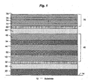
- Figure 1 schematically illustrates a substrate 12 bearing a coating in accordance with one embodiment of the invention. It should be understood that this drawing is intended merely to illustrate concepts of the invention and the thicknesses of the various layers in the drawing are not to scale.
- the substrate 12 in this drawing comprises a coating of the invention applied to a surface 14. While opaque substrates may be used, it is anticipated that for most applications of this invention, the substrate 12 will comprise a transparent or translucent material
- the substrate is a sheet-like substrate. While the substrate could take any form, one particularly suitable application for the invention is in windows, such as those used in architectural applications, automobile windshields, and oven doors, to name but a few examples.
- An inner dielectric layer 20 is applied on the surface 14 of the substrate 12.
- This Inner dielectric layer may be of any desired composition.
- suitable dielectric layers for this purpose include oxides of zinc, tin, indium, bismuth, titanium, hafnium, zirconium, and alloys thereof. While oxides are generally preferred due to their ease and low cost of application, other dielectric materials such as metal nitrides could be used if desired.
- the inner dielectric layer 20 may comprise a single layer of a single dielectric material, as shown. If such a single layer is used, it is generally preferred that this inner dielectric layer be formed of an oxide of zinc or an alloy or mixture thereof, such as a mixture of zinc oxide and bismuth oxide or tin oxide. It should be understood, though, that the single layer 20 shown in Figure 1 may be replaced with two or more layers of different dielectric materials.
- this inner dielectric layer Is beyond the scope of the present invention, it is generally preferred that at least a thin layer of zinc oxide be applied as an outermost layer (i.e., the layer farthest away from the substrate 12 and immediately adjacent the first infrared-reflective layer 30) as this is believed to enhance the optical properties of the film stack, at least if silver is used as the layer 30.
- the inner dielectric layer 20 is the only layer between the substrate and the first infrared-reflective layer 30, and the inner layer consists essentially of a zinc tin oxide layer, optionally having a thickness of less, than about 190 angstroms, perhaps preferably less than about 170 angstroms, and perhaps optimally less than about 140 angstroms.
- the next layer in the coating of Figure 1 is the first infrared-reflective layer 30.
- This first infrared-reflective layer is contiguous to, i.e., in direct physical contact with, the inner dielectric layer 20.
- Any suitable infrared-reflective material can be used for this layer.
- Silver, gold and copper, as well as alloys thereof, are the most commonly used infrared-reflective layers.
- the infrared-reflective layer 30 be formed of silver or silver combined with no more than about 5% gold, palladium or platinum.
- the infrared-reflective layer can also be formed of silver combined with no more than about 5% nickel, preferably no more than about 2% nickel, and perhaps optimally no more than about 0.2% nickel.
- a first sacrificial layer 32 is desirably applied over and contiguous to the first reflective layer 30.
- the primary purpose of this sacrificial layer 32 is to protect the underlying infrared-reflective layer 30 from chemical attack. Any material which is more readily oxidized than Is the infrared-reflective layer may be used as such a sacrificial layer.
- the sacrificial layer 32 comprises a layer of niobium deposited at a thickness sufficient to protect the infrared-reflective layer 30 from degradation both during sputtering of subsequent layers and from degradation during high temperature applications or tempering. Suitable thicknesses for such nioblum layers range from 7-25 angstroms, with a range of about 12-18 angstroms being preferred.
- niobium sacrificial layer may also be provided under the infrared-reflective layer 30.
- Barrier layers of niobium used in transparent film stacks are discussed in some detail in PCT international Publication No. WO 97/48649 .
- the intermediate dielectric stack (or middle coat") 40 is positioned between the first infrared-reflective layer 30 and a second infrared-reflective layer 60.
- This intermediate dielectric stack is formed of a plurality of intermediate/dielectric layers. While the number of intermediate dielectric layers can be varied as desired, it is preferred that.there be three such layers in the intermediate dielectric stack. While any suitable number of layers may be used in this intermediate dielectric stack 40, in one embodiment which has been found to work well, there are only three intermediate dielectric layers, with the bottom and top layers of this stack 40 both comprising zinc tin oxides, wherein a tin oxide layer is sandwiched between the two noted zinc tin oxide layers of the middle coat.
- the intermediate dielectric stack comprises alternating layers of a first dielectric (e.g., zinc tin oxide) and a second dielectric (e.g., tin oxide).
- the intermediate dielectric stack 40 includes a first intermediate layer 42, third intermediate layer 44 and fifth intermediate layer 46 each formed of a first dielectric material, and a second intermediate layer 52 and fourth intermediate layer 54 each formed of a second dielectric materials. While additional layers of any other material (e.g., a relatively thin layer of silica) can be included at any point deemed appropriate within the first stack 40, it is preferred that each of the illustrated layers be applied contiguous to at least one other layer of the intermediate dielectric stack 40.
- the second intermediate layer 52 preferably is contiguous to both the first intermediate layer 42 and the third intermediate layer 44.
- the fourth intermediate layer 54 preferably is contiguous to the third intermediate layer 44 and the fifth intermediate layer 46.
- each layer of the intermediate stack have a different microstructure from each dielectric layer contiguous thereto, preferably by forming contiguous layers of different materials.
- the first, third and fifth intermediate layers (42, 44 and 46, respectively) can optionally be formed of the same material, such as zinc tin oxide.
- the second and fourth intermediate layers (52 and 54, respectively) are desirably formed of the same dielectric material, such as tin oxide.
- each of these layers is kept relatively thin. It is preferred that the thickness of each of these layers be maintained well beneath one-quarter of the wavelength of the light of primary interest. If the substrate is used as a window, for example, maximizing transmission of visible light and reducing visible haze is paramount. As visible light is generally considered to be 3,000-7,000 angstroms in wavelength, each of the layers can optionally be less than about 700 angstroms in optimal thickness. (Optical thickness, which is a measure of the optical effect of a thin film on light transmitted therethrough, is the product of the physical thickness of the layer and the index of refraction of the material comprising the layer.
- a 200 angstroms layer of zinc tin oxide having an index of refraction of about 2.0 will have an optical thickness of about 400 angstroms.
- a maximum physical thickness of about 350 angstroms is desirable, with a maximum physical thickness of no more than about 300 angstroms being preferred.
- each of the intermediate dielectric layers of the intermediate dielectric stack 40 desirably have an optical thickness of no more than about 700 angstroms, with a maximum physical thickness of about 350 angstroms being preferred and a maximum physical thickness of about 300 angstroms being particularly preferred. While each layer is desirably no thicker than this maximum, all of the layers need not have the same thickness.
- the invention merely requires that the intermediate dielectric stack be formed of a plurality of intermediate dielectric layers comprising a tin oxide film region between two film regions comprising zinc tin oxide.
- the intermediate dielectric stack is formed of alternating layers of a first dielectric (e.g., zinc tin oxide) and a second dielectric (e.g. tin oxide). It is particularly preferred that the first and second dielectrics of this embodiment have an index of refraction which is relatively close. As these dielectrics desirably comprise different materials, it is unlikely that the indices of refraction will be identical.
- the index of refraction of these two materials should be within 10% of one another.
- the index of refraction of one of the two dielectrics should be between about 90% and 110% of the index of refraction of the other dielectric material.
- Pure zinc oxide is a polycrystalline material when applied in thin films via magnetron sputtering. Treating zinc oxide films at high temperatures, such as in tempering operations, tends to promote relatively rapid crystal growth. If a coating has zinc oxide layers that are too thick, this can contribute significantly to haze.
- Figure 1 illustrates a "double-silver" film stack which includes a second infrared-reflective layer 60 carried atop the intermediate dielectric stack 40.
- a sacrificial layer of niobium or any other suitable nucleation layer can be disposed between the intermediate dielectric stack 40 and the infrared-reflective layer 60.
- the outermost dielectric layer of the intermediate dielectric stack can be formed of an oxide sputtered from a target consisting essentially of zinc and tin.
- the materials useful in forming the first infrared-reflective layer 30 are also useful in forming the second infrared-reflective layer 60. It is anticipated that both of these layers will be formed of the same material. Preferably, both layers comprise silver, with the second, outer layer 60 being somewhat thicker than the inner layer 30. Similarly, a second sacrificial layer 62 of niobium or the like can be applied over the second infrared-reflective layer 60 to help protect the second infrared-reflective layer from oxiding or nitriding during subsequent processing or use.
- An outer dielectric layer desirably is applied over the outer infrared-reflective layer 60.
- the exact nature of this outer dielectric layer can be varied as desired. Any of a wide variety of single layers or film stacks known in the art can be used as the outermost layer or layers of the film stack. Optionally, none of the layers of this outer film stack have a physical thickness of more than about 225 angstroms or an optical thickness of more than about 450 angstroms.
- an outer dielectric stack 70 is applied over the sacrificial layer 62.
- This outer stack 70 may comprise, for example, zinc oxide or zinc tin oxide applied at about 60-70 angstroms.
- a layer of titanium nitride 76 can optionally be sandwiched between layers of silicon nitride 74, 78 and this sandwich is applied directly over a zinc oxide layer 72.
- the innermost of these silicon nitride layers 74 is on the order of 20-50 angstroms thick, the tin oxide layer 76 is about 12-15 angstroms and the outermost silicon nitride layer 78 is 150-180 angstroms.
- the present invention also contemplates a method of producing a coated substrate, e.g., a coated glass article.
- a substrate 12 having a surface 14 is provided. If so desired, this substrate surface 14 may be prepared by suitable washing or chemical preparation.
- the low-emissivity coating can optionally be deposited on the surface 14 of the substrate 12 as a series of discrete layers. These layers can be deposited in any desired fashion. In many cases, the layers will be deposited using a sputtering method, such as DC, AC and/or pulsed DC sputtering. One preferred method of depositing these layers utilizes DC magnetron sputtering, which is commonly used in the industry and one embodiment of which is described in Chapin's U.S. Patent 4,166,018 .
- magnetron sputtering deposition involves transporting a substrate through a series of low pressure zones in which the various films that make up the film stack are sequentially applied,
- Metallic films are sputtered from metallic sources or "targets" typically in an Inert atmosphere such as argon.
- the target may be formed of the desired dielectric itself (e.g., zinc oxide, titanium dioxide, or sub-oxides thereof). More commonly, though, the dielectric layers are applied by sputtering a metal target in a reactive atmosphere.
- a zinc targets will be sputtered in an oxidizing atmosphere; silicon nitride may be deposited by sputtering a silicon target (which may be doped with aluminum or the like to improve conductivity) in a reactive atmosphere containing nitrogen gas.
- the thickness of the films that are thus deposited may be controlled by varying the speed of the glass substrate through the coating compartments and by varying the power and sputtering rate of each individual target.
- the invention provides a low-emissivity coating having a middle coat comprising first and second film regions of zinc tin oxide separated by a film region of tin oxide.
- the first and second film regions of zinc tin oxide have a combined thickness of at least about 300 angstroms.
- the film region of tin oxide preferably has a thickness of less than 100 angstroms, more preferably between about 5 angstroms and about 80 angstroms, and optimally between about 30 angstroms and 70 angstroms (e.g., about 40-60 angstroms).
- the low-emissivity film stack includes the noted middle coat and first and second silver-containing infrared-reflective layers, wherein the second (i.e., outer) infrared-reflective layer is positioned directly on top of the second zinc tin oxide film region.
- the first zinc tin oxide film region comprises a discrete (e.g., homogenous) layer of zinc tin oxide
- the second zinc tin oxide film region comprises a discrete (e.g., homogenous layer of zinc tin oxide
- the tin oxide region comprises a discrete (e.g., homogenous) layer of tin oxide.
- An embodiment of this nature is illustrated in Figure 2 .
- Figure 2 schematically illustrates a substrate 112 bearing a low-emissivity coating including a middle coat 140 including a first film region comprising zinc tin oxide 142 and a second film region comprising zinc tin oxide 146, these two regions 142, 146 being separated by a middle film region comprising tin oxide 144.
- An inner dielectric layer 120 is applied on the surface 114 of the substrate 112. Materials useful for forming the inner dielectric layer are described above.
- the next layer in the coating of Figure 2 is the first infrared-reflective layer 130. Materials useful for forming the infrared-reflective layers have been described.
- a first sacrificial layer 132 is desirably applied over and contiguous to the first infrared-reflective layer 130. Materials useful for forming the sacrificial layer are described above.
- the middle coat 140 is positioned between the first infrared-reflective layer 130 and a second infrared-reflective layer 160.
- the middle coat 140 includes a film region of tin oxide 144 between two zinc tin oxide film regions (i.e., a first film region of zinc tin oxide 142 and a second film region of zinc tin oxide 146).
- the first film region 142 and the second film region 146 preferably have a combined thickness of at least about 300 angstroms.
- the film region 144 preferably includes or consists essentially of tin oxide.
- the film region 144 preferably has a thickness of less than 100 angstroms, more preferably between about 5 angstroms and about 80 angstroms, and perhaps optimally between about 30 angstroms and about 70 angstroms.
- the next layer of Figure 2 is the second infrared-reflective layer 160.
- materials useful for forming the infrared-reflective layers have been described.
- a second sacrificial layer 162 is desirably applied over and contiguous to the second infrared-reflective layer 160. Materials useful for forming the sacrificial layer have already been described.
- An outer layer 170 may optionally be provided over the second infrared-reflective layer 160 (and in some cases, over the second sacrificial layer 162). As noted above, the outer layer 170 may be a single layer or a film stack including more than one layer.
- one or more nucleation layers can be positioned underneath each infrared-reflective layer.
- a nucleation layer serves as a good foundation for the infrared-reflective layer.
- the layer can include nickelchrome, nickel-titanium, chromium, tungsten, tantalum or mixtures thereof.
- the first zinc tin oxide film region comprises a graded film region having a substantially continuously increasing (as measured moving further and further away from the substrate) concentration of tin oxide
- the second zinc tin oxide film region comprises a graded film region having a substantially continuously decreasing concentration of tin oxide.
- Figure 3 schematically illustrates a substrate 212 bearing a low-emissivity coating including a middle coat 240 including a first film region comprising zinc tin oxide 242 and a second film region comprising zinc tin oxide 246, the two zinc tin oxide regions 242, 246 being separated by a middle film region comprising tin oxide 244.
- an inner dielectric layer 220 is applied on the surface 214 of the substrate 212.
- the next layer in the coating of Figure 3 is the first infrared-reflective layer 230.
- a first sacrificial layer 232 is desirably applied over and contiguous to the first infrared-reflective layer 230.
- the middle coat 240 is positioned between the first infrared-reflective layer 230 and a second infrared-reflective layer 260.
- the middle coat 240 includes a first zinc tin oxide graded film region 242 having a substantially continuously increasing concentration of tin oxide and a second zinc tin oxide graded film region 246 having a substantially continuously decreasing concentration of tin oxide.
- the first graded film region 242 and the second graded film region 246 preferably have a combined thickness of at least 300 angstroms. Preferably there is at least some thickness of substantially pure or essentially pure tin oxide between film regions 242 and 246.
- the middle film region 244 preferably has a thickness of less than 100 angstroms, more preferably between about 5 angstroms and about 80 angstroms, and optimally between about 30 angstroms and about 70 angstroms.
- the next layer of Figure 3 is the second infrared-reflective layer 260.
- a second sacrificial layer 262 is desirably applied over and contiguous to the second infrared-reflective layer 260.
- An outer layer 270 may optionally be provided over the second infrared-reflective layer 260 (and in some cases, over the second sacrificial layer 262). As noted above, the outer layer 270 may be a single layer or a film stack including more than one layer.
- Figure 4 schematically illustrates a substrate 312 bearing a low-emissivity coating including three infrared-reflective layers and two middle coats 340 and 340'.
- An inner dielectric layer 320 is applied on the surface 314 of the substrate 312. Materials useful for forming the inner dielectric layer are described above.
- the next layer is the first infrared-reflective layer 330. Materials useful for forming the infrared-reflective layers have been described.
- a first sacrificial layer 332 is desirably applied over and contiguous to the first infrared-reflective layer 330. materials useful for forming the sacrificial layer are described above.
- a first middle coat 340 is positioned between the first infrared-reflective layer 330 and a second infrared-reflective layer 360.
- the first middle coat 340 includes a film region of tin oxide 344 between two zinc tin oxide film regions (i.e., a first film region of zinc tin oxide 342 and a second film region of zinc tin oxide 346).
- the first film region 342 and the second film region 346 preferably have a combined thickness of at least about 300 angstroms.
- the film region 344 preferably includes or consists essentially of tin oxide.
- the film region 344 preferably has a thickness of less than 100 angstroms, more preferably between about 5 angstroms and about 80 angstroms, and perhaps optimally between about 30 angstroms and about 70 angstroms.
- a second sacrificial layer 362 is desirably applied over and contiguous to the second infrared-reflective layer 330.
- a second middle coat 340' is positioned between the second infrared-reflective layer 360 and a third infrared-reflective layer 390.
- the second middle coat also includes a film region of tin oxide 344' between two zinc tin oxide film regions (i.e., a first film region of zinc tin oxide 342' and a second film region of zinc tin oxide 346'). These film regions preferably have substantially the same thickness as already described for the film regions of the first middle coat 340.
- a third sacrificial layer 392 is desirably applied over and contiguous to the third infrared-reflective layer 390.
- An outer layer 370 may optionally be provided over the third infrared-reflective layer 390 (and in some cases, over the third sacrificial layer 392). As noted above, the outer layer 370 may be a single layer or a film stack including more than one layer.
- the invention also provides methods for depositing a coating containing a middle coat comprising a tin oxide film region sandwiched between (e.g., directly between) first and second zinc tin oxide film regions.
- a method of forming a coating comprising providing a glass substrate and forming a coating on a major surface of the glass substrate, the coating containing a middle coat comprising a tin oxide film region disposed between first and second zinc tin oxide film regions.
- the method comprises providing a glass substrate and depositing in sequence from the substrate outwardly: (i) an inner dielectric layer; (ii) a first infrared-reflective layer; (iii) a middle coat comprising a tin oxide film region positioned between first and second zinc tin oxide film regions; (iv) a second infrared-reflective layer and v) an outer dielectric layer.
- the middle coat is deposited by sputtering, (optionally by AC or DC magnetron sputtering), although other methods are within the scope of the invention.
- the first zinc tin oxide film and the second zinc tin oxide film regions are each formed by sputtering targets each containing zinc and tin.
- the first zinc tin oxide firm region and the second zinc tin oxide film region are each formed by sputtering targets each containing between about 11 % and about 16% tin by weight with the remainder being zinc atoms.
- the middle coat includes graded film regions
- the first film region of zinc tin oxide is formed by depositing a substantially continuously increasing concentration of tin oxide
- the second film region of zinc tin oxide is formed by depositing a substantially continuously decreasing concentration of tin oxide.
- the middle coat can be deposited by arranging sputtering targets to produce a middle coat having the following structure: zinc tin oxide ⁇ tin oxide ⁇ zinc tin oxide, where each arrow represents a gradual (with increasing distance from the substrate) transition from one film composition to another.
- Figure 5 depicts a sputtering apparatus that can be used to deposit a middle coat of the invention.
- a substrate is conveyed through five sputtering bays, each optionally being provided with an oxidizing atmosphere.
- the substrate is conveyed through a first sputtering bay equipped with two targets each comprising zinc and tin.
- the substrate is conveyed through a second sputtering bay in which the first target comprises zinc and tin and the second target comprises (e.g., consists essentially of) tin.
- the substrate is conveyed through a third sputtering bay equipped with two targets each comprising (e.g., consisting essentially of) tin.
- the substrate is next conveyed through a fourth sputtering bay in which the first target comprises (e.g., consists essentially of) tin and the second target comprises zinc and tin.
- the substrate is conveyed through a fifth sputtering bay equipped with two targets each comprising (e.g., consisting essentially of) zinc and tin.
Landscapes
- Chemical & Material Sciences (AREA)
- Engineering & Computer Science (AREA)
- Chemical Kinetics & Catalysis (AREA)
- Materials Engineering (AREA)
- Organic Chemistry (AREA)
- Life Sciences & Earth Sciences (AREA)
- General Chemical & Material Sciences (AREA)
- Geochemistry & Mineralogy (AREA)
- Mechanical Engineering (AREA)
- Metallurgy (AREA)
- Surface Treatment Of Glass (AREA)
- Macromolecular Compounds Obtained By Forming Nitrogen-Containing Linkages In General (AREA)
Claims (16)
- Substrat de verre en forme de feuille (12 ; 112 ; 212 ; 312) ayant des première et seconde surfaces principales généralement opposées (14 ; 114 ; 214 ; 314), au moins l'une des surfaces principales (14 ; 114 ; 214 ; 314) portant un revêtement de faible émissivité, le revêtement comprenant, dans l'ordre, depuis le substrat vers l'extérieur :a) une couche diélectrique interne (20 ; 120 ; 220 ; 320) ;b) une première couche réfléchissant l'infrarouge (30 ; 130 ; 230 ; 330) ;c) une couche centrale (40 ; 140 ; 240 ; 340) comprenant une première région de film d'oxyde d'étain au zinc (42 ; 142 ; 242 ; 342), une région de film d'oxyde d'étain (52 ; 144 ; 244 ; 344), et une seconde région de film d'oxyde d'étain au zinc (44 ; 146 ; 246 ; 346), dans laquelle ladite région de film d'oxyde d'étain (52 ; 144 ; 244 ; 344) est positionnée entre lesdites première et seconde régions de film d'oxyde d'étain au zinc (42 ; 44 ; 142 ; 146 ; 242 ; 246 ; 342 ; 346) ;d) une seconde couche réfléchissant l'infrarouge (60 ; 160 ; 260 ; 360) ; ete) une couche diélectrique externe (70 ; 170 ; 270 ; 370).
- Substrat de verre selon la revendication 1, dans lequel la région de film d'oxyde d'étain (52 ; 144 ; 244 ; 344) a une épaisseur de moins de 100 angströms, de préférence comprise entre environ 5 angströms et environ 80 angströms, et idéalement entre environ 30 angströms et environ 70 angströms.
- Substrat de verre selon la revendication 1 ou la revendication 2, dans lequel les première et seconde régions de film d'oxyde d'étain au zinc (42 ; 44 ; 142 ; 146 ; 242 ; 246 ; 342 ; 346) ont une épaisseur combinée d'au moins environ 300 angströms.
- Substrat de verre selon l'une quelconque des revendications précédentes, dans lequel les première et seconde régions de film d'oxyde d'étain au zinc (42 ; 44 ; 142 ; 146 ; 242 ; 246 ; 342 ; 346) sont chacune déposées par pulvérisation depuis une ou plusieurs cibles comprenant chacune une matière pulvérisable contenant entre environ 11 % et environ 16% en poids d'étain, le reste étant du zinc.
- Substrat de verre selon l'une quelconque des revendications précédentes, dans lequel la seconde couche réfléchissant l'infrarouge (60 ; 160 ; 260 ; 360) est positionnée directement par dessus la seconde région de film d'oxyde d'étain au zinc (44 ; 146 ; 246 ; 346).
- Substrat de verre selon l'une quelconque des revendications précédentes, comprenant une couche bloquante (32 ; 132 ; 232 ; 332) disposée entre la première couche réfléchissant l'infrarouge (30 ; 130 ; 230 ; 330) et la couche centrale (40 ; 140 ; 240 ; 340).
- Substrat de verre selon l'une quelconque des revendications précédentes, dans lequel toutes les régions de film de la couche centrale (40 ; 140 ; 240 ; 340) comprennent au moins une certaine quantité d'oxyde d'étain.
- Substrat de verre selon l'une quelconque des revendications précédentes, dans lequel la première région de film d'oxyde d'étain au zinc est une région de film graduée qui comporte une concentration sensiblement continûment croissante d'oxyde d'étain et la seconde région de film d'oxyde d'étain au zinc est une région de film graduée qui comporte une concentration sensiblement décroissante d'oxyde d'étain.
- Procédé de production d'un article de verre revêtu, le procédé comprenant :a) la fourniture d'une feuille de verre (12 ; 112 ; 212. 312) ;b) la formation d'un revêtement sur une surface principale (14 ; 114 ; 214 ; 314) de la feuille de verre (12 ; 112 ; 212 ; 312) en déposant les régions de film suivantes dans l'ordre depuis ladite surface principale (14 ; 114 ; 214 ; 314) vers l'extérieur :i) une couche diélectrique interne (20 ; 120 ; 220 ; 320) ;ii) une première couche réfléchissant l'infrarouge (30 ; 130 ; 230 ; 330) ;iii) une couche centrale (40 ; 140 ; 240 ; 340) comprenant une première région de film d'oxyde d'étain au zinc (42 ; 142 ; 242 ; 342), une région de film d'oxyde d'étain (52 ; 144 ; 244 ; 344), et une seconde région de film d'oxyde d'étain au zinc (44 ; 146 ; 246 ; 346) ;iv) une seconde couche réfléchissant l'infrarouge (60 ; 160 ; 260 ; 360) ; etv) une couche diélectrique externe (70 ; 170 ; 270 ; 370).
- Procédé selon la revendication 9, dans lequel la région de film d'oxyde d'étain (52 ; 144 ; 244 ; 344) est déposée à une épaisseur de moins de 100 angströms, de préférence comprise entre environ 5 angströms et environ 80 angströms, et idéalement entre environ 30 angströms et environ 70 angströms.
- Procédé selon la revendication 9 ou la revendication 10, dans lequel les première et seconde régions de film d'oxyde d'étain au zinc (42 ; 44 ; 142 ; 146 ; 242 ; 246 ; 342 ; 346) sont déposées à une épaisseur combinée d'au moins environ 300 angströms.
- Procédé selon l'une quelconque des revendications 9 à 11, dans lequel les première et seconde régions de film d'oxyde d'étain au zinc (42 ; 44 ; 142 ; 146 ; 242 ; 246 ; 342 ; 346) sont chacune déposées par pulvérisation depuis une ou plusieurs cibles comprenant chacune une matière cible pulvérisable contenant entre environ 11 % et environ 16% en poids d'étain, le reste étant du zinc.
- Procédé selon l'une quelconque des revendications 9 à 12, dans lequel la seconde région de film réfléchissant l'infrarouge (60 ; 160 ; 260 ; 360) est positionnée directement par dessus la seconde région de film d'oxyde d'étain au zinc (44 ; 146 ; 246 ; 346).
- Procédé selon l'une quelconque des revendications 9 à 13, comprenant en outre une couche bloquante (32 ; 132 ; 232 ; 332) disposée entre la première région de film réfléchissant l'infrarouge (30 ; 130 ; 230 ; 330) et la couche centrale (40 ; 140 ; 240 ; 340).
- Procédé selon l'une quelconque des revendications 9 à 14, dans lequel toutes les régions de film de la couche centrale (40 ; 140 ; 240 ; 340) comprennent au moins une certaine quantité d'oxyde d'étain.
- Procédé selon l'une quelconque des revendications 9 à 15, dans lequel la première région de film d'oxyde d'étain au zinc est formée en déposant une concentration sensiblement continûment croissante d'oxyde d'étain et la seconde région de film d'oxyde d'étain au zinc est formée en déposant une concentration sensiblement continûment décroissante d'oxyde d'étain.
Applications Claiming Priority (2)
| Application Number | Priority Date | Filing Date | Title |
|---|---|---|---|
| US66679905P | 2005-03-31 | 2005-03-31 | |
| PCT/US2006/011973 WO2006105419A1 (fr) | 2005-03-31 | 2006-03-30 | Revetements anti-trouble a faible emissivite |
Publications (2)
| Publication Number | Publication Date |
|---|---|
| EP1866151A1 EP1866151A1 (fr) | 2007-12-19 |
| EP1866151B1 true EP1866151B1 (fr) | 2010-03-10 |
Family
ID=36686081
Family Applications (1)
| Application Number | Title | Priority Date | Filing Date |
|---|---|---|---|
| EP06740228A Expired - Lifetime EP1866151B1 (fr) | 2005-03-31 | 2006-03-30 | Revetements anti-trouble a faible emissivite |
Country Status (6)
| Country | Link |
|---|---|
| US (1) | US7632571B2 (fr) |
| EP (1) | EP1866151B1 (fr) |
| AT (1) | ATE460271T1 (fr) |
| CA (1) | CA2602675C (fr) |
| DE (1) | DE602006012817D1 (fr) |
| WO (1) | WO2006105419A1 (fr) |
Families Citing this family (57)
| Publication number | Priority date | Publication date | Assignee | Title |
|---|---|---|---|---|
| CN102512889B (zh) | 2005-01-13 | 2015-11-25 | 唐纳森公司 | 空气过滤器滤筒和空气滤清器组件 |
| US7572511B2 (en) | 2005-10-11 | 2009-08-11 | Cardinal Cg Company | High infrared reflection coatings |
| US7342716B2 (en) | 2005-10-11 | 2008-03-11 | Cardinal Cg Company | Multiple cavity low-emissivity coatings |
| US7339728B2 (en) | 2005-10-11 | 2008-03-04 | Cardinal Cg Company | Low-emissivity coatings having high visible transmission and low solar heat gain coefficient |
| EP2190554B1 (fr) | 2007-09-07 | 2013-01-09 | Donaldson Company, Inc. | Ensemble filtre à air |
| CN102474999B (zh) * | 2009-08-03 | 2016-09-07 | 3M创新有限公司 | 用于形成光学透明的导电金属或金属合金薄膜的方法以及由其制成的膜 |
| US10654747B2 (en) | 2010-03-29 | 2020-05-19 | Vitro Flat Glass Llc | Solar control coatings with subcritical copper |
| US9932267B2 (en) | 2010-03-29 | 2018-04-03 | Vitro, S.A.B. De C.V. | Solar control coatings with discontinuous metal layer |
| US10654748B2 (en) * | 2010-03-29 | 2020-05-19 | Vitro Flat Glass Llc | Solar control coatings providing increased absorption or tint |
| US9279910B2 (en) * | 2013-03-13 | 2016-03-08 | Intermolecular, Inc. | Color shift of high LSG low emissivity coating after heat treatment |
| US9790127B2 (en) | 2013-03-14 | 2017-10-17 | Intermolecular, Inc. | Method to generate high LSG low-emissivity coating with same color after heat treatment |
| EA029592B1 (ru) * | 2013-05-30 | 2018-04-30 | Агк Гласс Юроп | Низкоэмиссионное и солнцезащитное остекление |
| US8940400B1 (en) * | 2013-09-03 | 2015-01-27 | Guardian Industries Corp. | IG window unit including double silver coating having increased SHGC to U-value ratio, and corresponding coated article for use in IG window unit or other window |
| US9481924B2 (en) * | 2014-06-02 | 2016-11-01 | Intermolecular, Inc. | Seed layer for low-e applications |
| WO2016044293A1 (fr) | 2014-09-15 | 2016-03-24 | Donaldson Company, Inc. | Cartouches de filtre, ensembles purificateur d'air, logements, éléments, composants et procédés |
| EP3237089B1 (fr) | 2014-12-27 | 2020-05-20 | Donaldson Company, Inc. | Ensemble filtre à air et cartouche filtrante |
| US9745792B2 (en) | 2015-03-20 | 2017-08-29 | Cardinal Cg Company | Nickel-aluminum blocker film multiple cavity controlled transmission coating |
| US10759693B2 (en) * | 2018-07-16 | 2020-09-01 | Guardian Glass, LLC | Low-E matchable coated articles having absorber film and corresponding methods |
| US10301215B1 (en) | 2018-07-16 | 2019-05-28 | Guardian Glass, LLC | Low-E matchable coated articles having doped seed layer under silver, and corresponding methods |
| US10752541B2 (en) | 2018-07-16 | 2020-08-25 | Guardian Glass, LLC | Low-E matchable coated articles having doped seed layer under silver, and corresponding methods |
| US10787385B2 (en) * | 2018-07-16 | 2020-09-29 | Guardian Glass, LLC | Low-E matchable coated articles having absorber film and corresponding methods |
| US12350905B2 (en) | 2021-10-11 | 2025-07-08 | Vitro Flat Glass Llc | Heat-treatable coating having reduced haze |
| WO2024112552A1 (fr) | 2022-11-23 | 2024-05-30 | LuxWall, Inc. | Procédé de fabrication d'un panneau isolé sous vide à l'aide d'un traitement au laser d'un matériau d'étanchéité pour changer la stoechiométrie et/ou un ou plusieurs états d'oxydation |
| WO2024112487A1 (fr) | 2022-11-23 | 2024-05-30 | LuxWall, Inc. | Panneau isolé sous vide à contrainte de compression et/ou de traction optimisée dans le verre |
| WO2024112485A1 (fr) | 2022-11-23 | 2024-05-30 | LuxWall, Inc. | Panneau isolé sous vide à joint en couches |
| WO2024112407A1 (fr) | 2022-11-23 | 2024-05-30 | LuxWall, Inc. | Panneau isolé sous vide avec getter allongé |
| CA3252153A1 (en) | 2022-11-23 | 2024-05-30 | LuxWall, Inc. | Vacuum insulated panel with cte optimized edge seal |
| WO2024112554A1 (fr) | 2022-11-23 | 2024-05-30 | LuxWall, Inc. | Procédé de fabrication d'un panneau isolé sous vide avec une vitesse laser optimisée |
| WO2024112578A1 (fr) | 2022-11-23 | 2024-05-30 | LuxWall, Inc. | Procédé de fabrication d'un panneau isolé sous vide avec une durée d'émission laser |
| WO2024112875A1 (fr) | 2022-11-23 | 2024-05-30 | LuxWall, Inc. | Panneau isolé sous vide avec éléments d'espacement en céramique |
| WO2024112494A1 (fr) | 2022-11-23 | 2024-05-30 | LuxWall, Inc. | Panneau isolant sous vide avec piège à gaz ayant une phase cristalline ti-al-v et son procédé de fabrication |
| WO2024112484A1 (fr) | 2022-11-23 | 2024-05-30 | LuxWall, Inc. | Panneau isolé sous vide avec joint en couches et/ou son procédé de fabrication |
| WO2024112493A1 (fr) | 2022-11-23 | 2024-05-30 | LuxWall, Inc. | Panneau isolant sous vide avec joint stratifié et/ou son procédé de fabrication |
| US20240167318A1 (en) | 2022-11-23 | 2024-05-23 | LuxWall, Inc. | Vacuum insulated panel with optimized compressive and/or tensile stress in glass |
| EP4575169A3 (fr) | 2022-11-23 | 2025-07-02 | Luxwall, Inc. | Panneau isolé sous vide avec un joint comprenant de l'oxyde de tellure et/ou du bore et de l'oxyde de bismuth |
| CA3263282A1 (fr) | 2022-11-23 | 2024-05-30 | LuxWall, Inc. | Panneau isolé sous vide avec éléments d'espacement en céramique |
| US12410654B2 (en) | 2022-11-23 | 2025-09-09 | LuxWall, Inc. | Vacuum insulated panel with passivation layer |
| WO2024112757A1 (fr) | 2022-11-23 | 2024-05-30 | LuxWall, Inc. | Panneau à isolation sous vide avec couche de passivation |
| WO2024112483A1 (fr) | 2022-11-23 | 2024-05-30 | LuxWall, Inc. | Panneau isolé sous vide avec joint d'étanchéité comprenant de l'oxyde de tellure et/ou de l'oxyde de vanadium |
| EP4490382B1 (fr) | 2022-11-23 | 2025-04-30 | Luxwall, Inc. | Panneau isolant sous vide avec joint pour tube de pompage et/ou son procédé de fabrication |
| WO2024112514A1 (fr) | 2022-11-23 | 2024-05-30 | LuxWall, Inc. | Procédé de fabrication d'un panneau isolé sous vide à taille de faisceau laser optimisée |
| WO2024112482A1 (fr) | 2022-11-23 | 2024-05-30 | LuxWall, Inc. | Panneau isolant sous vide avec joint stratifié comprenant de l'oxyde de tellure et/ou de l'oxyde de vanadium |
| WO2024112624A1 (fr) | 2022-11-23 | 2024-05-30 | LuxWall, Inc. | Panneau à isolation sous vide avec joint multi-rangées |
| WO2024112513A1 (fr) | 2022-11-23 | 2024-05-30 | LuxWall, Inc. | Procédé de fabrication d'un panneau isolé sous vide avec un préchauffage et un chauffage au laser |
| WO2025207128A1 (fr) | 2024-03-25 | 2025-10-02 | LuxWall, Inc. | Panneau isolé sous vide avec trou et joint d'étanchéité pour tube d'évacuation et procédé |
| WO2025207127A1 (fr) | 2024-03-25 | 2025-10-02 | LuxWall, Inc. | Panneau isolé sous vide avec joint d'étanchéité pour tube d'évacuation et procédé |
| WO2025207159A1 (fr) | 2024-03-25 | 2025-10-02 | LuxWall, Inc. | Panneau isolé sous vide avec structure de montage de tube d'évacuation et rugosité de surface pour joint de tube |
| WO2025207148A1 (fr) | 2024-03-25 | 2025-10-02 | LuxWall, Inc. | Panneau isolé sous vide avec structure de montage de tube d'évacuation et procédé |
| WO2025212134A1 (fr) | 2024-04-01 | 2025-10-09 | LuxWall, Inc. | Panneau isolé sous vide avec joint d'extrémité de tube d'évacuation de verre et procédé |
| US20250305616A1 (en) | 2024-04-01 | 2025-10-02 | LuxWall, Inc. | Vacuum insulated panel with glass evacuation tube and method |
| US20250320768A1 (en) | 2024-04-11 | 2025-10-16 | LuxWall, Inc. | Vacuum insulated panel with high condensation resistance factor (crf) |
| US20250320769A1 (en) | 2024-04-12 | 2025-10-16 | LuxWall, Inc. | Vacuum insulated panel with glass removal proximate edge seal |
| US12612821B2 (en) | 2024-04-16 | 2026-04-28 | LuxWall, Inc. | Vacuum insulated panel with improved thermal performance proximate edge of glass during asymmetric thermal conditions |
| US20250341129A1 (en) | 2024-05-03 | 2025-11-06 | LuxWall, Inc. | Vacuum insulated panel with glass substrates having edge(s) with reduced surface roughness and/or seal designed to reduce stress |
| US20250354431A1 (en) | 2024-05-15 | 2025-11-20 | LuxWall, Inc. | Vacuum insulated panel with trough for getter |
| US20250353278A1 (en) | 2024-05-20 | 2025-11-20 | LuxWall, Inc. | Vacuum insulated panel with thermal conductivity/diffusivity additive(s) for seal material |
| US20260028872A1 (en) | 2024-07-29 | 2026-01-29 | LuxWall, Inc. | Vacuum insulated panel configured for measurement of pressure in evacuated gap |
Family Cites Families (54)
| Publication number | Priority date | Publication date | Assignee | Title |
|---|---|---|---|---|
| US4166018A (en) | 1974-01-31 | 1979-08-28 | Airco, Inc. | Sputtering process and apparatus |
| US4737379A (en) | 1982-09-24 | 1988-04-12 | Energy Conversion Devices, Inc. | Plasma deposited coatings, and low temperature plasma method of making same |
| DE3241516A1 (de) * | 1982-11-10 | 1984-05-10 | Robert Bosch Gmbh, 7000 Stuttgart | Mehrschichtsystem fuer waermeschutzanwendung |
| US4619729A (en) | 1984-02-14 | 1986-10-28 | Energy Conversion Devices, Inc. | Microwave method of making semiconductor members |
| US4610771A (en) | 1984-10-29 | 1986-09-09 | Ppg Industries, Inc. | Sputtered films of metal alloy oxides and method of preparation thereof |
| US4716086A (en) | 1984-12-19 | 1987-12-29 | Ppg Industries, Inc. | Protective overcoat for low emissivity coated article |
| US4786563A (en) | 1985-12-23 | 1988-11-22 | Ppg Industries, Inc. | Protective coating for low emissivity coated articles |
| US4828825A (en) * | 1986-09-15 | 1989-05-09 | University Of Miami | Infrared reflecting composition for topical application to the skin |
| US4859532A (en) | 1986-11-27 | 1989-08-22 | Asahi Glass Company Ltd. | Transparent laminated product |
| GB8630791D0 (en) | 1986-12-23 | 1987-02-04 | Glaverbel | Coating glass |
| DE3700076A1 (de) * | 1987-01-02 | 1988-07-14 | Flachglas Ag | Mehrscheibenisolierglas fuer kuehlraeume oder dergleichen |
| US4898789A (en) | 1988-04-04 | 1990-02-06 | Ppg Industries, Inc. | Low emissivity film for automotive heat load reduction |
| US4965121A (en) | 1988-09-01 | 1990-10-23 | The Boc Group, Inc. | Solar control layered coating for glass windows |
| GB8900165D0 (en) | 1989-01-05 | 1989-03-01 | Glaverbel | Glass coating |
| GB8900166D0 (en) | 1989-01-05 | 1989-03-01 | Glaverbel | Glass coating |
| US5506037A (en) | 1989-12-09 | 1996-04-09 | Saint Gobain Vitrage International | Heat-reflecting and/or electrically heatable laminated glass pane |
| US5194989A (en) | 1990-05-07 | 1993-03-16 | Mcdonnell Douglas Corporation | Dielectric combiner including first and second dielectric materials having indices of refraction greater than 2.0 |
| EP0463812B1 (fr) | 1990-06-27 | 1995-12-13 | Texas Instruments Incorporated | Fenêtre protectrice, transparente à l'infrarouge |
| SG47839A1 (en) * | 1990-07-05 | 1998-04-17 | Asahi Glass Co Ltd | A low emissivity film |
| US5419969A (en) | 1990-07-05 | 1995-05-30 | Asahi Glass Company Ltd. | Low emissivity film |
| US5532062A (en) | 1990-07-05 | 1996-07-02 | Asahi Glass Company Ltd. | Low emissivity film |
| US5203977A (en) | 1991-03-11 | 1993-04-20 | Regents Of The University Of California | Magnetron sputtered boron films and TI/B multilayer structures |
| US5248545A (en) | 1991-06-24 | 1993-09-28 | Ford Motor Company | Anti-iridescent coatings with gradient refractive index |
| US5225926A (en) | 1991-09-04 | 1993-07-06 | International Business Machines Corporation | Durable optical elements fabricated from free standing polycrystalline diamond and non-hydrogenated amorphous diamond like carbon (dlc) thin films |
| SG45418A1 (en) | 1991-10-30 | 1998-01-16 | Asahi Glass Co Ltd | Method of making a heat treated coated glass |
| US5296302A (en) | 1992-03-27 | 1994-03-22 | Cardinal Ig Company | Abrasion-resistant overcoat for coated substrates |
| US5302449A (en) | 1992-03-27 | 1994-04-12 | Cardinal Ig Company | High transmittance, low emissivity coatings for substrates |
| US5337191A (en) | 1993-04-13 | 1994-08-09 | Photran Corporation | Broad band pass filter including metal layers and dielectric layers of alternating refractive index |
| CA2129488C (fr) | 1993-08-12 | 2004-11-23 | Olivier Guiselin | Substrats transparents munis d'un empilement de couches minces, application aux vitrages d'isolation thermique et/ou de protection solaire |
| US5438235A (en) | 1993-10-05 | 1995-08-01 | General Electric Company | Electrostatic shield to reduce wall damage in an electrodeless high intensity discharge lamp |
| DK0758306T3 (da) | 1994-05-03 | 1999-05-10 | Cardinal Ig Co | Transparent genstand med beskyttelsesfilm af siliciumnitrid |
| US5502595A (en) | 1994-06-03 | 1996-03-26 | Industrial Technology Research Institute | Color filters and their preparation |
| DE19520843A1 (de) | 1995-06-08 | 1996-12-12 | Leybold Ag | Scheibe aus durchscheinendem Werkstoff sowie Verfahren zu ihrer Herstellung |
| DE19541937C1 (de) | 1995-11-10 | 1996-11-28 | Ver Glaswerke Gmbh | Wärmedämmendes Schichtsystem mit niedriger Emissivität, hoher Transmission und neutraler Ansicht in Reflexion und Transmission |
| US6316111B1 (en) | 1996-03-01 | 2001-11-13 | Cardinal Cg Company | Heat-emperable coated glass article |
| GB9606281D0 (en) | 1996-03-26 | 1996-05-29 | Glaverbel | Coated substrate for a transparent assembly with high selectivity |
| US5821001A (en) | 1996-04-25 | 1998-10-13 | Ppg Industries, Inc. | Coated articles |
| US5942338A (en) | 1996-04-25 | 1999-08-24 | Ppg Industries Ohio, Inc. | Coated articles |
| US6231999B1 (en) | 1996-06-21 | 2001-05-15 | Cardinal Ig Company | Heat temperable transparent coated glass article |
| FR2755962B1 (fr) | 1996-11-21 | 1998-12-24 | Saint Gobain Vitrage | Vitrage comprenant un substrat muni d'un empilement de couches minces pour la protection solaire et/ou l'isolation thermique |
| FR2757151B1 (fr) | 1996-12-12 | 1999-01-08 | Saint Gobain Vitrage | Vitrage comprenant un substrat muni d'un empilement de couches minces pour la protection solaire et/ou l'isolation thermique |
| US5944964A (en) | 1997-02-13 | 1999-08-31 | Optical Coating Laboratory, Inc. | Methods and apparatus for preparing low net stress multilayer thin film coatings |
| JP3724936B2 (ja) | 1997-09-18 | 2005-12-07 | セントラル硝子株式会社 | 低放射ガラス積層体 |
| US6030671A (en) | 1998-01-09 | 2000-02-29 | Msc Specialty Films, Inc. | Low emissivity window films |
| JP2000302486A (ja) | 1999-04-15 | 2000-10-31 | Nippon Sheet Glass Co Ltd | 日射遮蔽性透光板およびこれを用いた日射遮蔽性複層透光板 |
| JPH11307987A (ja) | 1998-04-16 | 1999-11-05 | Nippon Sheet Glass Co Ltd | 電磁波フィルタ |
| US6899953B1 (en) | 1998-05-08 | 2005-05-31 | Ppg Industries Ohio, Inc. | Shippable heat-treatable sputter coated article and zinc cathode sputtering target containing low amounts of tin |
| EP1010677A1 (fr) | 1998-12-17 | 2000-06-21 | Saint-Gobain Vitrage | Systeme de couches reflechissant la chaleur pour substrats transparents |
| JP3477148B2 (ja) | 1999-12-02 | 2003-12-10 | カーディナル・シージー・カンパニー | 耐曇り性透明フィルム積層体 |
| DE10206787A1 (de) * | 2001-07-16 | 2003-02-06 | Hans-Juergen Schaefer | Verfahren und Vorrichtung zur sequentiellen Herstellung von kupferkaschierten HDI-Multilayer-Laminaten |
| MXPA04007578A (es) | 2002-02-11 | 2004-11-10 | Ppg Ind Ohio Inc | Recubrimiento de control solar. |
| ATE382585T1 (de) | 2003-06-24 | 2008-01-15 | Cardinal Cg Co | Konzentrationsmodulierte beschichtungen |
| US7217460B2 (en) * | 2004-03-11 | 2007-05-15 | Guardian Industries Corp. | Coated article with low-E coating including tin oxide interlayer |
| EP1828074B1 (fr) * | 2004-11-08 | 2020-06-17 | AGC Glass Europe | Vitrage |
-
2006
- 2006-03-30 DE DE602006012817T patent/DE602006012817D1/de not_active Expired - Lifetime
- 2006-03-30 CA CA2602675A patent/CA2602675C/fr not_active Expired - Fee Related
- 2006-03-30 US US11/394,992 patent/US7632571B2/en not_active Expired - Fee Related
- 2006-03-30 WO PCT/US2006/011973 patent/WO2006105419A1/fr not_active Ceased
- 2006-03-30 AT AT06740228T patent/ATE460271T1/de not_active IP Right Cessation
- 2006-03-30 EP EP06740228A patent/EP1866151B1/fr not_active Expired - Lifetime
Also Published As
| Publication number | Publication date |
|---|---|
| DE602006012817D1 (de) | 2010-04-22 |
| CA2602675A1 (fr) | 2006-10-05 |
| EP1866151A1 (fr) | 2007-12-19 |
| ATE460271T1 (de) | 2010-03-15 |
| WO2006105419A1 (fr) | 2006-10-05 |
| CA2602675C (fr) | 2014-03-11 |
| US7632571B2 (en) | 2009-12-15 |
| US20070237980A1 (en) | 2007-10-11 |
Similar Documents
| Publication | Publication Date | Title |
|---|---|---|
| US7632571B2 (en) | Haze-resistant low-emissivity coatings | |
| CA2393294C (fr) | Empilements de films transparents resistant au trouble | |
| EP1594812B1 (fr) | Panneau de vitrage portant une superposition de revetement | |
| EP1734019B1 (fr) | Article revêtu avec couche de réflexion IR et procédé de fabrication de cet article | |
| EP3071530B1 (fr) | Article pouvant être traité thermiquement recouvert d'un revêtement à faible émissivité (low-e) comportant une couche à base de stannate de zinc entre des couches réfléchissant l'infrarouge et procédé correspondant | |
| CN1777690B (zh) | 采用钛与铝材料的混合物涂覆的衬底,制备该衬底的方法和钛与铝金属的阴极靶材 | |
| EP3510003B1 (fr) | Article revêtu présentant une couche réfléchissant les ir et son procédé de fabrication | |
| EP1851354B2 (fr) | Procede de fabrication de revetement de faible teneur en e a l'aide d'une cible contenant du zinc ceramique, et cible utilisee dans ledit procede | |
| EP1630142B1 (fr) | Revêtement à couches minces comportant une couche avec du niobium et du titane | |
| CN104936925B (zh) | 具附加金属的含氧化锌层的低辐射涂层的涂层制品 | |
| US20030165694A1 (en) | Thin film coating having niobium-titanium layer | |
| EP1546055A1 (fr) | Articles avec revetement a faible emissivite thermotraitables et procedes de fabrication de ces articles par pluverisation d'argon dans une atmosphere a teneur en oxygene | |
| KR20130051521A (ko) | 열처리 가능한 저방사 유리 및 그 제조방법 | |
| CA3054935A1 (fr) | Article revetu presentant un revetement a faible emissivite presentant une/des couche(s) reflechissant les ir et une/des couche(s) dielectrique(s) d'oxyde de titane dope au niobium et procede pour sa fabrication | |
| EP4007744A1 (fr) | Substrat revêtu | |
| EP1754691B1 (fr) | Empilement de couches transparentes resistantes à la formation de voile | |
| CN113614046A (zh) | 具有吸收膜的低e可匹配涂覆制品及相应方法 | |
| US10179946B2 (en) | Coated article having low-E coating with IR reflecting layer(s) and niobium bismuth based high index layer and method of making same | |
| WO2025186542A1 (fr) | Vitre revêtue | |
| CN114430732A (zh) | 具有吸收膜的低e可匹配涂覆制品及相应方法 | |
| EP4007743A1 (fr) | Substrat revêtu et trempable |
Legal Events
| Date | Code | Title | Description |
|---|---|---|---|
| PUAI | Public reference made under article 153(3) epc to a published international application that has entered the european phase |
Free format text: ORIGINAL CODE: 0009012 |
|
| 17P | Request for examination filed |
Effective date: 20071001 |
|
| AK | Designated contracting states |
Kind code of ref document: A1 Designated state(s): AT BE BG CH CY CZ DE DK EE ES FI FR GB GR HU IE IS IT LI LT LU LV MC NL PL PT RO SE SI SK TR |
|
| 17Q | First examination report despatched |
Effective date: 20080115 |
|
| DAX | Request for extension of the european patent (deleted) | ||
| GRAP | Despatch of communication of intention to grant a patent |
Free format text: ORIGINAL CODE: EPIDOSNIGR1 |
|
| GRAS | Grant fee paid |
Free format text: ORIGINAL CODE: EPIDOSNIGR3 |
|
| GRAA | (expected) grant |
Free format text: ORIGINAL CODE: 0009210 |
|
| AK | Designated contracting states |
Kind code of ref document: B1 Designated state(s): AT BE BG CH CY CZ DE DK EE ES FI FR GB GR HU IE IS IT LI LT LU LV MC NL PL PT RO SE SI SK TR |
|
| REG | Reference to a national code |
Ref country code: GB Ref legal event code: FG4D |
|
| REG | Reference to a national code |
Ref country code: CH Ref legal event code: EP |
|
| REG | Reference to a national code |
Ref country code: IE Ref legal event code: FG4D |
|
| REF | Corresponds to: |
Ref document number: 602006012817 Country of ref document: DE Date of ref document: 20100422 Kind code of ref document: P |
|
| REG | Reference to a national code |
Ref country code: NL Ref legal event code: VDEP Effective date: 20100310 |
|
| PG25 | Lapsed in a contracting state [announced via postgrant information from national office to epo] |
Ref country code: LT Free format text: LAPSE BECAUSE OF FAILURE TO SUBMIT A TRANSLATION OF THE DESCRIPTION OR TO PAY THE FEE WITHIN THE PRESCRIBED TIME-LIMIT Effective date: 20100310 |
|
| LTIE | Lt: invalidation of european patent or patent extension |
Effective date: 20100310 |
|
| PG25 | Lapsed in a contracting state [announced via postgrant information from national office to epo] |
Ref country code: AT Free format text: LAPSE BECAUSE OF FAILURE TO SUBMIT A TRANSLATION OF THE DESCRIPTION OR TO PAY THE FEE WITHIN THE PRESCRIBED TIME-LIMIT Effective date: 20100310 Ref country code: FI Free format text: LAPSE BECAUSE OF FAILURE TO SUBMIT A TRANSLATION OF THE DESCRIPTION OR TO PAY THE FEE WITHIN THE PRESCRIBED TIME-LIMIT Effective date: 20100310 Ref country code: PL Free format text: LAPSE BECAUSE OF FAILURE TO SUBMIT A TRANSLATION OF THE DESCRIPTION OR TO PAY THE FEE WITHIN THE PRESCRIBED TIME-LIMIT Effective date: 20100310 Ref country code: SI Free format text: LAPSE BECAUSE OF FAILURE TO SUBMIT A TRANSLATION OF THE DESCRIPTION OR TO PAY THE FEE WITHIN THE PRESCRIBED TIME-LIMIT Effective date: 20100310 Ref country code: LV Free format text: LAPSE BECAUSE OF FAILURE TO SUBMIT A TRANSLATION OF THE DESCRIPTION OR TO PAY THE FEE WITHIN THE PRESCRIBED TIME-LIMIT Effective date: 20100310 |
|
| PG25 | Lapsed in a contracting state [announced via postgrant information from national office to epo] |
Ref country code: GR Free format text: LAPSE BECAUSE OF FAILURE TO SUBMIT A TRANSLATION OF THE DESCRIPTION OR TO PAY THE FEE WITHIN THE PRESCRIBED TIME-LIMIT Effective date: 20100611 Ref country code: BE Free format text: LAPSE BECAUSE OF FAILURE TO SUBMIT A TRANSLATION OF THE DESCRIPTION OR TO PAY THE FEE WITHIN THE PRESCRIBED TIME-LIMIT Effective date: 20100310 Ref country code: CY Free format text: LAPSE BECAUSE OF FAILURE TO SUBMIT A TRANSLATION OF THE DESCRIPTION OR TO PAY THE FEE WITHIN THE PRESCRIBED TIME-LIMIT Effective date: 20100310 Ref country code: EE Free format text: LAPSE BECAUSE OF FAILURE TO SUBMIT A TRANSLATION OF THE DESCRIPTION OR TO PAY THE FEE WITHIN THE PRESCRIBED TIME-LIMIT Effective date: 20100310 Ref country code: ES Free format text: LAPSE BECAUSE OF FAILURE TO SUBMIT A TRANSLATION OF THE DESCRIPTION OR TO PAY THE FEE WITHIN THE PRESCRIBED TIME-LIMIT Effective date: 20100621 Ref country code: MC Free format text: LAPSE BECAUSE OF NON-PAYMENT OF DUE FEES Effective date: 20100331 Ref country code: NL Free format text: LAPSE BECAUSE OF FAILURE TO SUBMIT A TRANSLATION OF THE DESCRIPTION OR TO PAY THE FEE WITHIN THE PRESCRIBED TIME-LIMIT Effective date: 20100310 Ref country code: RO Free format text: LAPSE BECAUSE OF FAILURE TO SUBMIT A TRANSLATION OF THE DESCRIPTION OR TO PAY THE FEE WITHIN THE PRESCRIBED TIME-LIMIT Effective date: 20100310 Ref country code: SE Free format text: LAPSE BECAUSE OF FAILURE TO SUBMIT A TRANSLATION OF THE DESCRIPTION OR TO PAY THE FEE WITHIN THE PRESCRIBED TIME-LIMIT Effective date: 20100310 |
|
| REG | Reference to a national code |
Ref country code: CH Ref legal event code: PL |
|
| PG25 | Lapsed in a contracting state [announced via postgrant information from national office to epo] |
Ref country code: SK Free format text: LAPSE BECAUSE OF FAILURE TO SUBMIT A TRANSLATION OF THE DESCRIPTION OR TO PAY THE FEE WITHIN THE PRESCRIBED TIME-LIMIT Effective date: 20100310 Ref country code: BG Free format text: LAPSE BECAUSE OF FAILURE TO SUBMIT A TRANSLATION OF THE DESCRIPTION OR TO PAY THE FEE WITHIN THE PRESCRIBED TIME-LIMIT Effective date: 20100610 Ref country code: CZ Free format text: LAPSE BECAUSE OF FAILURE TO SUBMIT A TRANSLATION OF THE DESCRIPTION OR TO PAY THE FEE WITHIN THE PRESCRIBED TIME-LIMIT Effective date: 20100310 Ref country code: IS Free format text: LAPSE BECAUSE OF FAILURE TO SUBMIT A TRANSLATION OF THE DESCRIPTION OR TO PAY THE FEE WITHIN THE PRESCRIBED TIME-LIMIT Effective date: 20100710 |
|
| PLBE | No opposition filed within time limit |
Free format text: ORIGINAL CODE: 0009261 |
|
| STAA | Information on the status of an ep patent application or granted ep patent |
Free format text: STATUS: NO OPPOSITION FILED WITHIN TIME LIMIT |
|
| PG25 | Lapsed in a contracting state [announced via postgrant information from national office to epo] |
Ref country code: DK Free format text: LAPSE BECAUSE OF FAILURE TO SUBMIT A TRANSLATION OF THE DESCRIPTION OR TO PAY THE FEE WITHIN THE PRESCRIBED TIME-LIMIT Effective date: 20100310 Ref country code: PT Free format text: LAPSE BECAUSE OF FAILURE TO SUBMIT A TRANSLATION OF THE DESCRIPTION OR TO PAY THE FEE WITHIN THE PRESCRIBED TIME-LIMIT Effective date: 20100712 Ref country code: IE Free format text: LAPSE BECAUSE OF NON-PAYMENT OF DUE FEES Effective date: 20100330 |
|
| 26N | No opposition filed |
Effective date: 20101213 |
|
| PG25 | Lapsed in a contracting state [announced via postgrant information from national office to epo] |
Ref country code: CH Free format text: LAPSE BECAUSE OF NON-PAYMENT OF DUE FEES Effective date: 20100331 Ref country code: LI Free format text: LAPSE BECAUSE OF NON-PAYMENT OF DUE FEES Effective date: 20100331 |
|
| PG25 | Lapsed in a contracting state [announced via postgrant information from national office to epo] |
Ref country code: IT Free format text: LAPSE BECAUSE OF FAILURE TO SUBMIT A TRANSLATION OF THE DESCRIPTION OR TO PAY THE FEE WITHIN THE PRESCRIBED TIME-LIMIT Effective date: 20100310 |
|
| PG25 | Lapsed in a contracting state [announced via postgrant information from national office to epo] |
Ref country code: HU Free format text: LAPSE BECAUSE OF FAILURE TO SUBMIT A TRANSLATION OF THE DESCRIPTION OR TO PAY THE FEE WITHIN THE PRESCRIBED TIME-LIMIT Effective date: 20100911 Ref country code: LU Free format text: LAPSE BECAUSE OF NON-PAYMENT OF DUE FEES Effective date: 20100330 |
|
| PG25 | Lapsed in a contracting state [announced via postgrant information from national office to epo] |
Ref country code: TR Free format text: LAPSE BECAUSE OF FAILURE TO SUBMIT A TRANSLATION OF THE DESCRIPTION OR TO PAY THE FEE WITHIN THE PRESCRIBED TIME-LIMIT Effective date: 20100310 |
|
| PGFP | Annual fee paid to national office [announced via postgrant information from national office to epo] |
Ref country code: GB Payment date: 20130327 Year of fee payment: 8 Ref country code: FR Payment date: 20130405 Year of fee payment: 8 |
|
| GBPC | Gb: european patent ceased through non-payment of renewal fee |
Effective date: 20140330 |
|
| REG | Reference to a national code |
Ref country code: FR Ref legal event code: ST Effective date: 20141128 |
|
| PG25 | Lapsed in a contracting state [announced via postgrant information from national office to epo] |
Ref country code: GB Free format text: LAPSE BECAUSE OF NON-PAYMENT OF DUE FEES Effective date: 20140330 Ref country code: FR Free format text: LAPSE BECAUSE OF NON-PAYMENT OF DUE FEES Effective date: 20140331 |
|
| PGFP | Annual fee paid to national office [announced via postgrant information from national office to epo] |
Ref country code: DE Payment date: 20190327 Year of fee payment: 14 |
|
| REG | Reference to a national code |
Ref country code: DE Ref legal event code: R119 Ref document number: 602006012817 Country of ref document: DE |
|
| PG25 | Lapsed in a contracting state [announced via postgrant information from national office to epo] |
Ref country code: DE Free format text: LAPSE BECAUSE OF NON-PAYMENT OF DUE FEES Effective date: 20201001 |