EP1867444A2 - Robotersimulationsvorrichtung - Google Patents
Robotersimulationsvorrichtung Download PDFInfo
- Publication number
- EP1867444A2 EP1867444A2 EP07011384A EP07011384A EP1867444A2 EP 1867444 A2 EP1867444 A2 EP 1867444A2 EP 07011384 A EP07011384 A EP 07011384A EP 07011384 A EP07011384 A EP 07011384A EP 1867444 A2 EP1867444 A2 EP 1867444A2
- Authority
- EP
- European Patent Office
- Prior art keywords
- hand
- case
- interference
- robot
- simulation apparatus
- Prior art date
- Legal status (The legal status is an assumption and is not a legal conclusion. Google has not performed a legal analysis and makes no representation as to the accuracy of the status listed.)
- Withdrawn
Links
Images

Classifications
-
- B—PERFORMING OPERATIONS; TRANSPORTING
- B25—HAND TOOLS; PORTABLE POWER-DRIVEN TOOLS; MANIPULATORS
- B25J—MANIPULATORS; CHAMBERS PROVIDED WITH MANIPULATION DEVICES
- B25J9/00—Program-controlled manipulators
- B25J9/16—Program controls
- B25J9/1656—Program controls characterised by programming, planning systems for manipulators
- B25J9/1671—Program controls characterised by programming, planning systems for manipulators characterised by simulation, either to verify existing program or to create and verify new program, CAD/CAM oriented, graphic oriented programming systems
Definitions
- the present invention relates to a robot simulation apparatus, which simulates a picking operation with a robot hand in an animated manner.
- a robot simulation apparatus for simulating a robot operation in an animated manner has been known from the disclosure of Japanese Patent Publication No.2001-105359 .
- the robot simulation apparatus as disclosed in this Patent Document comprises a storage portion for storing shape models for a robot, a work piece, and peripheral equipment, a display portion for displaying the shape models on a display screen, and a dimension setting portion for selecting a specific shape model having dimensions to be changed and setting the dimensions of the shape model on the display screen.
- a robot that is provided with a camera as a vision sensor and performs a picking operation, is disclosed in Japanese Patent Publication No. 2000-293695 , although this example is not concerned with a robot simulation apparatus.
- the camera is used for photographing work pieces, which are randomly piled up in a case. Image processing of the photographed image is performed by an image processor, and the position and posture of the work pieces are thereby recognized enabling automated picking of the piled-up work pieces.
- the robot simulation apparatus disclosed in Japanese Patent Publication No. 2001-105359 facilitates setting and changing of the size of the work pieces or peripheral equipment so that the robot can be operated without interfering with its surrounding when environmental conditions including the robot have changed.
- the above-mentioned apparatus does not change the dimensions of the robot hand by simulating the picking operation with the robot hand. Therefore, in a picking operation performed with the robot hand, it is necessary to operate the robot hand repeatedly in the actual work-site area in order to examine whether or not the robot hand can reach work pieces contained in the case or whether or not the wall of the case interferes with the operation of the robot hand.
- the design of a robot hand must depend heavily upon the knowledge and experience of a designer, which is very time consuming.
- a robot simulation apparatus which lays out a shape model of a robot equipped with a hand, and shape models of a case and work pieces contained in the case, on a display screen in a prescribed positional relationship, and simulates a picking operation of the robot, which picks up a work piece with the hand
- the apparatus comprising: a case dimension setting portion for setting the shape model of the case to a prescribed shape and dimension; an interference checking portion for checking for interference between the hand and the case when the robot is operated to take out work pieces from a side of a inner wall of the case, and if there is interference, identifying it; a hand changing portion for changing the shape model of the hand so that there is no interference between the hand and the case when it is determined by the interference checking portion that there is interference between the hand and the case; and a product data acquiring portion for acquiring data on actual product dimension of the hand from the shape model of the hand changed by the hand changing portion.
- the case dimension setting portion can be used to set the shape model of a case having a multiplicity of work pieces randomly contained therein to a prescribed shape, along with dimensions corresponding to the actual case.
- the interference checking portion can be used to check for interference between the hand and the case during the simulated picking operation, and if there is interference, the interference portion can be identified.
- the hand changing portion can be used to change the shape model of the hand based on the identified interference portion such that the hand does not interfere with the case.
- the product data acquiring portion can be used to acquire data on actual product dimensions of the hand from the changed shape model of the hand to be stored in memory.
- a designer of the robot hand can reflect the data on the product dimensions stored in the memory to design the actual robot hand, so that the time required for design change in response to the change of environmental conditions surrounding the robot can be decreased, and design of the robot hand can be thereby simplified.
- the hand changing portion can be used to change the dimensions of the interference portion.
- the hand changing portion to change the dimensions of the identified interference portion, the time required for design of the robot hand can be substantially decreased.
- the length of the robot hand can be changed to any size.
- the hand changing portion can be used to select a hand of an arbitrary shape from a library of hands stored in the memory.
- the same effect as claimed in claim 2 can be obtained by using the hand changing portion to select, for example, a hand of arbitrary length from the library (database) in which data on a multiplicity of shape models are stored.
- the interference checking portion can be used to check for interference between peripheral equipment and the like, added to the hand of the robot and the case, and when it is determined that there is interference between the peripheral equipment and the case, the hand changing portion can be used to change the shape model of the hand so that peripheral equipment and the like does not interfere with the case.
- the interference checking portion can be used to check for interference caused by peripheral equipment provided on the hand, interference can be checked in various portions in which interference in the picking operation may be problem, so that the range of application of the robot simulation apparatus can be expanded.
- peripheral equipment may include a vision sensor used to photograph work pieces contained in the case.
- interference between the vision sensor provided on the robot hand and the case can be checked so that design of the robot hand can be carried out under conditions closer to the actual picking operation at a work-site area.
- a robot simulation apparatus (hereinafter referred to as "simulation apparatus") according to the present invention will be described in detail below with reference to the drawings.
- simulation apparatus A robot simulation apparatus (hereinafter referred to as "simulation apparatus") according to the present invention will be described in detail below with reference to the drawings.
- same or like parts common to various drawings are denoted by same reference numerals or symbols, and duplicate explanation is omitted.
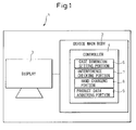
- a simulation apparatus 1 of the present embodiment is capable of performing off-line simulation of picking work (operation) executed by a real robot, and has, as shown in Fig. 1, an apparatus main body 2 having a control function, and a display 3 connected to the apparatus main body 2 for displaying a graphic image.
- the apparatus main body 2 includes a keyboard and a mouse as a pointing device for designating a specific position on the screen of the display 3.
- the apparatus main body 2 has a controller 4 and an interface (not shown).
- the controller 4 has a CPU (not shown) and various types of memory (not shown), such as a ROM, RAM, and flash memory.
- a system program for controlling the entire simulation apparatus is stored in ROM.
- the RAM is used for temporary storage of data for processing executed by the CPU.
- programs and various data necessary for execution of the present method are stored in the flash memory.
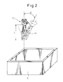
- the controller 4 is electrically connected via an interface to the display 3, the keyboard, mouse, robot controller (not shown) and the CAD device for transmission and reception of an electric signal. From the CAD device, shape data on 3-dimensional models of the robot 10 having the robot hand 11, the case and work pieces (not shown) contained therein are transmitted and stored in the flash memory so that the robot 10 and the case 5 may be displayed in a prescribed positional relationship on the screen of the display 3. The input signal is processed by the controller 4 so as to allow various functions to be carried out.
- the controller 4 consists essentially of the following components.
- the controller 4 has a data acquiring portion (not shown) for acquiring various shape data on the robot 10 and the case 5 transmitted from the CAD device and displaying them on the screen of the display 3, a case dimension setting portion 6 for setting the shape model of the case for containing work pieces of a prescribed shape and dimension, an interference checking portion 7 for checking whether or not there is interference between the robot hand 11 and the case 5 at the time of operating the robot 10 to take out the work pieces from the side of the inner wall of the case 5, a hand dimension changing portion (hand changing portion) 8 for changing the dimension of the robot hand 11 at the interference portion when it is determined by the interference checking portion 7 that there is interference between the robot hand 11 and the case 5, and a product data acquiring portion 9 for acquiring data on the actual product dimensions of the robot hand 11 from the shape model of the robot hand 22 changed by the hand dimension changing portion.
- the interference portion between the robot hand 11 and the case 5 is identified by the interference checking portion 7.
- a liquid crystal display or a CRT display may be applied so as to display a 3-dimensional model of the robot 10 having the hand 11 and a 3-dimensional model of the case 5 graphically on the screen.
- the robot hand 11 and the case 5 are arranged in a prescribed positional relationship. This positional relationship is selected so as to reproduce the positional relationship on the actual work-site area.
- the method of graphic display is arbitrary, and may be a solid model display, frame model display, wire model display, or the like.
- 3-dimensional data of the robot hand 11 and the case 5 can be directly read-in from the CAD device, but may be indirectly captured via a storage medium.
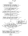
- step S1 3-dimensional models of the case 5, the work pieces (not shown), and the robot hand 11 are read-in from the CAD device, and at step S2, are graphically displayed on the screen of the display 3 in a relative positional relationship corresponding to the actual work environment.
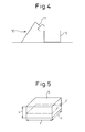
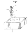
- step S3 as shown in Fig. 5, the shape and dimensions of the case 5 forming a rectangular parallelepiped, that is, the height s, width t, and depth u are set (case dimension setting portion 6).
- the size of an imaginary occupied space V, occupied with respect to the case 5 by a multiplicity of work pieces randomly contained in the case 5 is set.
- the imaginary occupied space V is set as a 3-dimensional space.
- the attitude (permissible inclination angle ⁇ ) of the robot hand 11 when a work piece can be grasped by the robot hand 11 from the side of the inner wall of the case 5 is determined in the imaginary occupied space V of the work pieces. More specifically, it is checked whether or not the work piece can be grasped when the robot hand 11 descends vertically at four corners of the upper and lower surfaces of the imaginary occupied space V of the work pieces (eight corners in total). If the work piece cannot be grasped, it is checked whether or not the work piece can be grasped by tilting the robot hand 11 at an arbitrary angle.
- the robot hand 11 is operated in simulation, and it is checked whether or not there is interference between the robot hand 11 and the inner wall of the case 5 when a work piece is to be picked out from the inner wall side of the case 5 (the inner wall side including the corners of the case 5 and the four sides of the case 5) (the interference checking portion 7). At the same time, the interference portion between the robot hand 11 and the case 5 is identified.
- the dimension of the robot hand 11 at the interference portion is changed (the hand changing portion 8). More specifically, the length dimension L of the robot hand 11 is suitably changed repeatedly in the range of 1/2 - 3 times initially set value until it is determined by the interference checking portion that there is no interference.
- step S8 data on the actual product dimensions of the robot hand 11 is acquired from the shape model of the robot hand 11 when the robot hand 11 is changed so as to not interfere with the case 5 (the product data acquiring portion 9).
- time required for design change of the robot hand 11 corresponding to change of environmental conditions surrounding the robot 10 can be decreased by reflecting the length L of the robot hand 11 stored in memory on the design of the actual robot hand, and the design of the robot hand 11 can be carried out more easily.
- this variant is the robot hand 11A of Fig. 2 provided with a vision sensor 12. Only the difference will be described below, constituents common to the previous embodiment are denoted by same reference numerals and symbols and duplicate explanation thereof is omitted.
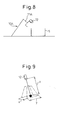
- the field-of-view space of the vision sensor 12 is set at step SA1 that follows the steps S3 and S4. More specifically, the range of space in which the field of view of the vision sensor 12 is not obstructed by the robot hand 11A is designated. In this variant, the width x of the field of view, the length y of the field of view, and the standoff value z are designated (Fig. 9).
- the robot hand 11A is moved along the frame-like edge of the inside of the case 5 (the side of the inner wall including the corners of the case 5 and the four sides of the case 5) and it is determined that the field-of-view space of the vision sensor 12 coincides with or is larger than the size of the case 5 (?).
- step S6 it is determined at step S6 whether or not the work piece can be grasped with no interference between the vision sensor 12 and the case 5. If it is determined that the work piece can be grasped with no interference, the processing flow proceeds to step S8. If it is determined that there is interference, the dimension of the robot hand 11A is changed at step S7 so that the sensor 12 and the case 5 do not interfere with each other (the hand changing portion 8).
- interference between the vision sensor 12 provided as peripheral equipment on the robot hand 11A and the case 5 can be checked, and simulation can be performed under conditions close to the actual operation of the robot hand, so that the range of application of the robot simulation apparatus 1A can be expanded, and the precision of the simulation can be improved.
- the present invention is not limited to the above- described embodiments, but can be carried out in various modification without departing from the spirit and scope of the invention.
- the length L of the robot hand 11 can be changed, it is also possible as an alternative to change the robot hand by selecting a robot hand of different dimension from a library in which data on a multiplicity of shape models of robot hands are stored.
- Robot hands of not only different length, but also different types can be registered in the library, so that it is possible to flexibly responds flexibly to the diverse forms of picking operations.
Landscapes
- Engineering & Computer Science (AREA)
- Robotics (AREA)
- Mechanical Engineering (AREA)
- Manipulator (AREA)
- Numerical Control (AREA)
Applications Claiming Priority (1)
| Application Number | Priority Date | Filing Date | Title |
|---|---|---|---|
| JP2006166482A JP2007334678A (ja) | 2006-06-15 | 2006-06-15 | ロボットシミュレーション装置 |
Publications (1)
| Publication Number | Publication Date |
|---|---|
| EP1867444A2 true EP1867444A2 (de) | 2007-12-19 |
Family
ID=38573215
Family Applications (1)
| Application Number | Title | Priority Date | Filing Date |
|---|---|---|---|
| EP07011384A Withdrawn EP1867444A2 (de) | 2006-06-15 | 2007-06-11 | Robotersimulationsvorrichtung |
Country Status (4)
| Country | Link |
|---|---|
| US (1) | US20070293986A1 (de) |
| EP (1) | EP1867444A2 (de) |
| JP (1) | JP2007334678A (de) |
| CN (1) | CN101088718A (de) |
Cited By (1)
| Publication number | Priority date | Publication date | Assignee | Title |
|---|---|---|---|---|
| US10603788B2 (en) | 2016-09-05 | 2020-03-31 | Fanuc Corporation | Robot simulation apparatus |
Families Citing this family (24)
| Publication number | Priority date | Publication date | Assignee | Title |
|---|---|---|---|---|
| JP5233709B2 (ja) * | 2009-02-05 | 2013-07-10 | 株式会社デンソーウェーブ | ロボットシミュレーション画像表示システム |
| JP5665333B2 (ja) * | 2010-03-10 | 2015-02-04 | キヤノン株式会社 | 情報処理装置および情報処理装置の制御方法 |
| KR101778030B1 (ko) * | 2010-09-27 | 2017-09-26 | 삼성전자주식회사 | 로봇 및 그 제어방법 |
| JP2012135821A (ja) * | 2010-12-24 | 2012-07-19 | Seiko Epson Corp | ロボットシミュレーション装置、ロボットシミュレーション方法、及びロボットシミュレーションプログラム |
| US9132546B2 (en) * | 2011-04-14 | 2015-09-15 | Mitsubishi Electric Corporation | Robot control apparatus |
| JP5144785B2 (ja) * | 2011-04-18 | 2013-02-13 | ファナック株式会社 | ロボットの着目部位と周辺物との干渉を予測する方法及び装置 |
| KR101607586B1 (ko) * | 2012-04-17 | 2016-03-30 | 마키노 밀링 머신 주식회사 | 공작기계의 간섭판정방법 및 간섭판정장치 |
| JP5926403B2 (ja) * | 2012-12-25 | 2016-05-25 | 平田機工株式会社 | 搬送システム |
| JP5672322B2 (ja) * | 2013-03-14 | 2015-02-18 | 株式会社安川電機 | ロボット装置 |
| JP5672326B2 (ja) * | 2013-03-19 | 2015-02-18 | 株式会社安川電機 | ロボットシステム |
| JP6036662B2 (ja) * | 2013-11-22 | 2016-11-30 | 三菱電機株式会社 | ロボットシミュレーション装置、プログラム、記録媒体及び方法 |
| JP5850958B2 (ja) | 2014-01-24 | 2016-02-03 | ファナック株式会社 | ワークを撮像するためのロボットプログラムを作成するロボットプログラミング装置 |
| JP6632208B2 (ja) * | 2015-03-24 | 2020-01-22 | キヤノン株式会社 | 情報処理装置、情報処理方法、プログラム |
| JP6285405B2 (ja) | 2015-12-04 | 2018-02-28 | ファナック株式会社 | 工作機械及びロボットを備えた複合システム |
| DE102017119393A1 (de) | 2016-09-05 | 2018-03-08 | Fanuc Corporation | Robotersimulationsgerät |
| JP6438510B2 (ja) * | 2017-03-09 | 2018-12-12 | ファナック株式会社 | 治具設計支援装置及びロボットシミュレーション装置 |
| JP6857101B2 (ja) * | 2017-07-31 | 2021-04-14 | 株式会社キーエンス | ロボットシミュレーション装置及びロボットシミュレーション方法 |
| JP6894829B2 (ja) * | 2017-11-22 | 2021-06-30 | 株式会社日立プラントコンストラクション | 構造物撤去シミュレーション方法 |
| JP7065886B2 (ja) * | 2017-12-28 | 2022-05-12 | 株式会社Fuji | 情報提供装置、情報提供方法及びプログラム |
| US11926058B2 (en) | 2017-12-28 | 2024-03-12 | Fuji Corporation | Information providing device, information providing method and program |
| JP7124509B2 (ja) * | 2018-07-19 | 2022-08-24 | オムロン株式会社 | シミュレーション装置、シミュレーションプログラムおよびシミュレーション方法 |
| JP7123885B2 (ja) * | 2019-09-13 | 2022-08-23 | 株式会社東芝 | ハンドリング装置、制御装置、および保持方法 |
| JPWO2021261242A1 (de) * | 2020-06-23 | 2021-12-30 | ||
| JP7657170B2 (ja) * | 2022-03-08 | 2025-04-04 | 株式会社日立製作所 | 修正装置、修正方法、および修正プログラム |
Family Cites Families (18)
| Publication number | Priority date | Publication date | Assignee | Title |
|---|---|---|---|---|
| US4754415A (en) * | 1984-10-12 | 1988-06-28 | Diffracto Ltd. | Robotic alignment and part simulation |
| JPS62229380A (ja) * | 1986-03-29 | 1987-10-08 | Toshiba Corp | 3次元物体表示装置 |
| NL8600831A (nl) * | 1986-04-02 | 1987-11-02 | Oce Nederland Bv | Werkwijze voor het opwekken en bewerken van modellen van twee- of driedimensionale objecten in een computer en voor het weergeven van die modellen op een display. |
| US4831549A (en) * | 1987-07-28 | 1989-05-16 | Brigham Young University | Device and method for correction of robot inaccuracy |
| US4985846A (en) * | 1989-05-11 | 1991-01-15 | Fallon Patrick J | Acoustical/optical bin picking system |
| JPH0699375A (ja) * | 1992-09-18 | 1994-04-12 | Kawasaki Heavy Ind Ltd | ロボット操作訓練装置 |
| US5495410A (en) * | 1994-08-12 | 1996-02-27 | Minnesota Mining And Manufacturing Company | Lead-through robot programming system |
| JPH11134017A (ja) * | 1997-10-27 | 1999-05-21 | Honda Motor Co Ltd | オフラインティーチング方法 |
| US6161051A (en) * | 1998-05-08 | 2000-12-12 | Rockwell Technologies, Llc | System, method and article of manufacture for utilizing external models for enterprise wide control |
| JP3377465B2 (ja) * | 1999-04-08 | 2003-02-17 | ファナック株式会社 | 画像処理装置 |
| JP3537362B2 (ja) * | 1999-10-12 | 2004-06-14 | ファナック株式会社 | ロボットシステム用グラフィック表示装置 |
| JP3715537B2 (ja) * | 2001-02-19 | 2005-11-09 | 本田技研工業株式会社 | 多関節ロボットの干渉回避方法およびプログラム |
| JP3782679B2 (ja) * | 2001-05-09 | 2006-06-07 | ファナック株式会社 | 干渉回避装置 |
| SE525108C2 (sv) * | 2002-12-30 | 2004-11-30 | Abb Research Ltd | Metod och system för programmering av en industrirobot, datorprogramprodukt, datorläsbart medium samt användning |
| JP3805310B2 (ja) * | 2003-01-30 | 2006-08-02 | ファナック株式会社 | ワーク取出し装置 |
| JP4441409B2 (ja) * | 2003-03-25 | 2010-03-31 | ローツェ株式会社 | ロボットシミュレーション装置、および、シミュレーションプログラム |
| JP3732494B2 (ja) * | 2003-10-31 | 2006-01-05 | ファナック株式会社 | シミュレーション装置 |
| SE526119C2 (sv) * | 2003-11-24 | 2005-07-05 | Abb Research Ltd | Metod och system för programmering av en industrirobot |
-
2006
- 2006-06-15 JP JP2006166482A patent/JP2007334678A/ja active Pending
-
2007
- 2007-06-11 EP EP07011384A patent/EP1867444A2/de not_active Withdrawn
- 2007-06-12 US US11/808,657 patent/US20070293986A1/en not_active Abandoned
- 2007-06-14 CN CNA2007101091845A patent/CN101088718A/zh active Pending
Cited By (1)
| Publication number | Priority date | Publication date | Assignee | Title |
|---|---|---|---|---|
| US10603788B2 (en) | 2016-09-05 | 2020-03-31 | Fanuc Corporation | Robot simulation apparatus |
Also Published As
| Publication number | Publication date |
|---|---|
| US20070293986A1 (en) | 2007-12-20 |
| CN101088718A (zh) | 2007-12-19 |
| JP2007334678A (ja) | 2007-12-27 |
Similar Documents
| Publication | Publication Date | Title |
|---|---|---|
| EP1867444A2 (de) | Robotersimulationsvorrichtung | |
| EP1864764B1 (de) | Robotersimulationsvorrichtung | |
| EP3171237B1 (de) | Simulator, simulationsverfahren und simulationsprogramm | |
| US11511415B2 (en) | System and method for robotic bin picking | |
| US10410339B2 (en) | Simulator, simulation method, and simulation program | |
| US10401844B2 (en) | Simulator, simulation method, and simulation program | |
| JP2005135278A (ja) | シミュレーション装置 | |
| JP3537362B2 (ja) | ロボットシステム用グラフィック表示装置 | |
| JP5113666B2 (ja) | ロボット教示システム及びロボットの動作のシミュレーション結果の表示方法 | |
| EP1769890A2 (de) | Gerät zur Robotersimulation | |
| EP1881383A2 (de) | Simulationsvorrichtung eines Robotersystems | |
| JP4153528B2 (ja) | ロボットシミュレーションのための装置、プログラム、記録媒体及び方法 | |
| EP1661669A2 (de) | Gerät zur Erzeugung eines Bearbeitungsprogrammes | |
| EP2082850A2 (de) | Erzeugungsvorrichtung eines verarbeitenden Roboterprogramms | |
| EP1798616A2 (de) | Offline-Programmiervorrichtung | |
| CN114080590B (zh) | 使用先进扫描技术的机器人料箱拾取系统和方法 | |
| JP7674464B2 (ja) | 視覚センサの出力から得られる3次元位置情報を用いるシミュレーション装置 | |
| CN109648568B (zh) | 机器人控制方法、系统及存储介质 | |
| US10724963B2 (en) | Device and method for calculating area to be out of inspection target of inspection system | |
| CN110682288A (zh) | 机器人程序生成装置 | |
| JP4961405B2 (ja) | シミュレーション装置の画像データ生成装置 | |
| WO2022208963A1 (ja) | ロボット制御用のキャリブレーション装置 | |
| EP3330813B1 (de) | Simulator, simulationsverfahren und simulationsprogramm | |
| EP3722052A1 (de) | Verfahren zur bestimmung der kameraplatzierung in einer roboterzellumgebung | |
| EP4302938A1 (de) | Anzeigesystem und lehrsystem |
Legal Events
| Date | Code | Title | Description |
|---|---|---|---|
| PUAI | Public reference made under article 153(3) epc to a published international application that has entered the european phase |
Free format text: ORIGINAL CODE: 0009012 |
|
| AK | Designated contracting states |
Kind code of ref document: A2 Designated state(s): AT BE BG CH CY CZ DE DK EE ES FI FR GB GR HU IE IS IT LI LT LU LV MC MT NL PL PT RO SE SI SK TR |
|
| AX | Request for extension of the european patent |
Extension state: AL BA HR MK YU |
|
| STAA | Information on the status of an ep patent application or granted ep patent |
Free format text: STATUS: THE APPLICATION HAS BEEN WITHDRAWN |
|
| 18W | Application withdrawn |
Effective date: 20080829 |