EP1867532A1 - Génerateur de gaz - Google Patents
Génerateur de gaz Download PDFInfo
- Publication number
- EP1867532A1 EP1867532A1 EP07018732A EP07018732A EP1867532A1 EP 1867532 A1 EP1867532 A1 EP 1867532A1 EP 07018732 A EP07018732 A EP 07018732A EP 07018732 A EP07018732 A EP 07018732A EP 1867532 A1 EP1867532 A1 EP 1867532A1
- Authority
- EP
- European Patent Office
- Prior art keywords
- gas
- inflator
- combustion
- cap
- pressurized
- Prior art date
- Legal status (The legal status is an assumption and is not a legal conclusion. Google has not performed a legal analysis and makes no representation as to the accuracy of the status listed.)
- Granted
Links
- 239000007789 gas Substances 0.000 claims abstract description 759
- 238000002485 combustion reaction Methods 0.000 claims abstract description 164
- 239000000567 combustion gas Substances 0.000 claims abstract description 133
- 238000007599 discharging Methods 0.000 claims abstract description 76
- 238000002788 crimping Methods 0.000 claims abstract description 13
- 239000003795 chemical substances by application Substances 0.000 claims description 171
- 230000004888 barrier function Effects 0.000 claims description 45
- 230000002093 peripheral effect Effects 0.000 claims description 34
- XKRFYHLGVUSROY-UHFFFAOYSA-N Argon Chemical compound [Ar] XKRFYHLGVUSROY-UHFFFAOYSA-N 0.000 claims description 24
- 239000007800 oxidant agent Substances 0.000 claims description 18
- 238000003466 welding Methods 0.000 claims description 14
- IDCPFAYURAQKDZ-UHFFFAOYSA-N 1-nitroguanidine Chemical compound NC(=N)N[N+]([O-])=O IDCPFAYURAQKDZ-UHFFFAOYSA-N 0.000 claims description 13
- 238000002844 melting Methods 0.000 claims description 13
- 230000008018 melting Effects 0.000 claims description 13
- 229910052786 argon Inorganic materials 0.000 claims description 12
- 239000001307 helium Substances 0.000 claims description 12
- 229910052734 helium Inorganic materials 0.000 claims description 12
- SWQJXJOGLNCZEY-UHFFFAOYSA-N helium atom Chemical compound [He] SWQJXJOGLNCZEY-UHFFFAOYSA-N 0.000 claims description 12
- 230000000694 effects Effects 0.000 description 93
- DHEQXMRUPNDRPG-UHFFFAOYSA-N strontium nitrate Chemical compound [Sr+2].[O-][N+]([O-])=O.[O-][N+]([O-])=O DHEQXMRUPNDRPG-UHFFFAOYSA-N 0.000 description 20
- 239000000446 fuel Substances 0.000 description 18
- 239000000463 material Substances 0.000 description 18
- 239000000203 mixture Substances 0.000 description 18
- 230000000630 rising effect Effects 0.000 description 18
- 230000009471 action Effects 0.000 description 14
- QVGXLLKOCUKJST-UHFFFAOYSA-N atomic oxygen Chemical compound [O] QVGXLLKOCUKJST-UHFFFAOYSA-N 0.000 description 12
- 238000004891 communication Methods 0.000 description 12
- 239000001301 oxygen Substances 0.000 description 12
- 229910052760 oxygen Inorganic materials 0.000 description 12
- DPXJVFZANSGRMM-UHFFFAOYSA-N acetic acid;2,3,4,5,6-pentahydroxyhexanal;sodium Chemical compound [Na].CC(O)=O.OCC(O)C(O)C(O)C(O)C=O DPXJVFZANSGRMM-UHFFFAOYSA-N 0.000 description 10
- 235000019812 sodium carboxymethyl cellulose Nutrition 0.000 description 10
- MYMOFIZGZYHOMD-UHFFFAOYSA-N Dioxygen Chemical compound O=O MYMOFIZGZYHOMD-UHFFFAOYSA-N 0.000 description 9
- 239000007767 bonding agent Substances 0.000 description 9
- 229910001882 dioxygen Inorganic materials 0.000 description 9
- 239000001768 carboxy methyl cellulose Substances 0.000 description 8
- 229920001027 sodium carboxymethylcellulose Polymers 0.000 description 8
- 239000002253 acid Substances 0.000 description 7
- 239000004927 clay Substances 0.000 description 7
- 239000011261 inert gas Substances 0.000 description 7
- VYPSYNLAJGMNEJ-UHFFFAOYSA-N Silicium dioxide Chemical compound O=[Si]=O VYPSYNLAJGMNEJ-UHFFFAOYSA-N 0.000 description 6
- 238000005304 joining Methods 0.000 description 6
- IATRAKWUXMZMIY-UHFFFAOYSA-N strontium oxide Chemical group [O-2].[Sr+2] IATRAKWUXMZMIY-UHFFFAOYSA-N 0.000 description 6
- 230000008859 change Effects 0.000 description 5
- 238000004519 manufacturing process Methods 0.000 description 5
- 150000003536 tetrazoles Chemical class 0.000 description 5
- IJGRMHOSHXDMSA-UHFFFAOYSA-N Atomic nitrogen Chemical compound N#N IJGRMHOSHXDMSA-UHFFFAOYSA-N 0.000 description 4
- UQSXHKLRYXJYBZ-UHFFFAOYSA-N Iron oxide Chemical compound [Fe]=O UQSXHKLRYXJYBZ-UHFFFAOYSA-N 0.000 description 4
- WABPQHHGFIMREM-UHFFFAOYSA-N lead(0) Chemical compound [Pb] WABPQHHGFIMREM-UHFFFAOYSA-N 0.000 description 4
- FGIUAXJPYTZDNR-UHFFFAOYSA-N potassium nitrate Chemical compound [K+].[O-][N+]([O-])=O FGIUAXJPYTZDNR-UHFFFAOYSA-N 0.000 description 4
- 229920000877 Melamine resin Polymers 0.000 description 3
- XOZUGNYVDXMRKW-AATRIKPKSA-N azodicarbonamide Chemical class NC(=O)\N=N\C(N)=O XOZUGNYVDXMRKW-AATRIKPKSA-N 0.000 description 3
- SMVZDCVZXKQERC-UHFFFAOYSA-N guanidine;nitrous acid Chemical compound ON=O.NC(N)=N SMVZDCVZXKQERC-UHFFFAOYSA-N 0.000 description 3
- 150000002357 guanidines Chemical class 0.000 description 3
- 229940083094 guanine derivative acting on arteriolar smooth muscle Drugs 0.000 description 3
- JDSHMPZPIAZGSV-UHFFFAOYSA-N melamine Chemical compound NC1=NC(N)=NC(N)=N1 JDSHMPZPIAZGSV-UHFFFAOYSA-N 0.000 description 3
- -1 nitroguanidine (NQ) Chemical class 0.000 description 3
- 239000007787 solid Substances 0.000 description 3
- 238000012360 testing method Methods 0.000 description 3
- JYEUMXHLPRZUAT-UHFFFAOYSA-N 1,2,3-triazine Chemical compound C1=CN=NN=C1 JYEUMXHLPRZUAT-UHFFFAOYSA-N 0.000 description 2
- FYADHXFMURLYQI-UHFFFAOYSA-N 1,2,4-triazine Chemical class C1=CN=NC=N1 FYADHXFMURLYQI-UHFFFAOYSA-N 0.000 description 2
- MQHZNFQPUJDVKD-UHFFFAOYSA-N 1-amino-1-nitroguanidine Chemical compound NC(=N)N(N)[N+]([O-])=O MQHZNFQPUJDVKD-UHFFFAOYSA-N 0.000 description 2
- PAWQVTBBRAZDMG-UHFFFAOYSA-N 2-(3-bromo-2-fluorophenyl)acetic acid Chemical compound OC(=O)CC1=CC=CC(Br)=C1F PAWQVTBBRAZDMG-UHFFFAOYSA-N 0.000 description 2
- VPIXQGUBUKFLRF-UHFFFAOYSA-N 3-(2-chloro-5,6-dihydrobenzo[b][1]benzazepin-11-yl)-N-methyl-1-propanamine Chemical compound C1CC2=CC=C(Cl)C=C2N(CCCNC)C2=CC=CC=C21 VPIXQGUBUKFLRF-UHFFFAOYSA-N 0.000 description 2
- 239000005995 Aluminium silicate Substances 0.000 description 2
- 239000004156 Azodicarbonamide Substances 0.000 description 2
- QPLDLSVMHZLSFG-UHFFFAOYSA-N Copper oxide Chemical compound [Cu]=O QPLDLSVMHZLSFG-UHFFFAOYSA-N 0.000 description 2
- 239000005751 Copper oxide Substances 0.000 description 2
- 229920002907 Guar gum Polymers 0.000 description 2
- OAKJQQAXSVQMHS-UHFFFAOYSA-N Hydrazine Chemical compound NN OAKJQQAXSVQMHS-UHFFFAOYSA-N 0.000 description 2
- 239000004354 Hydroxyethyl cellulose Substances 0.000 description 2
- 229920000663 Hydroxyethyl cellulose Polymers 0.000 description 2
- 239000005909 Kieselgur Substances 0.000 description 2
- 239000004372 Polyvinyl alcohol Substances 0.000 description 2
- 239000004115 Sodium Silicate Substances 0.000 description 2
- 229920002472 Starch Polymers 0.000 description 2
- 229910000831 Steel Inorganic materials 0.000 description 2
- PNEYBMLMFCGWSK-UHFFFAOYSA-N aluminium oxide Inorganic materials [O-2].[O-2].[O-2].[Al+3].[Al+3] PNEYBMLMFCGWSK-UHFFFAOYSA-N 0.000 description 2
- 235000012211 aluminium silicate Nutrition 0.000 description 2
- 150000001540 azides Chemical class 0.000 description 2
- 235000019399 azodicarbonamide Nutrition 0.000 description 2
- 239000000440 bentonite Substances 0.000 description 2
- 229910000278 bentonite Inorganic materials 0.000 description 2
- SVPXDRXYRYOSEX-UHFFFAOYSA-N bentoquatam Chemical compound O.O=[Si]=O.O=[Al]O[Al]=O SVPXDRXYRYOSEX-UHFFFAOYSA-N 0.000 description 2
- 239000011230 binding agent Substances 0.000 description 2
- CJZGTCYPCWQAJB-UHFFFAOYSA-L calcium stearate Chemical compound [Ca+2].CCCCCCCCCCCCCCCCCC([O-])=O.CCCCCCCCCCCCCCCCCC([O-])=O CJZGTCYPCWQAJB-UHFFFAOYSA-L 0.000 description 2
- 235000013539 calcium stearate Nutrition 0.000 description 2
- 239000008116 calcium stearate Substances 0.000 description 2
- STIAPHVBRDNOAJ-UHFFFAOYSA-N carbamimidoylazanium;carbonate Chemical compound NC(N)=N.NC(N)=N.OC(O)=O STIAPHVBRDNOAJ-UHFFFAOYSA-N 0.000 description 2
- XPCFIDKRNBCWOS-UHFFFAOYSA-N carbonic acid 1,2-diaminoguanidine Chemical compound C(O)(O)=O.NNC(=N)NN XPCFIDKRNBCWOS-UHFFFAOYSA-N 0.000 description 2
- XEVRDFDBXJMZFG-UHFFFAOYSA-N carbonyl dihydrazine Chemical compound NNC(=O)NN XEVRDFDBXJMZFG-UHFFFAOYSA-N 0.000 description 2
- 229920002678 cellulose Polymers 0.000 description 2
- 239000001913 cellulose Substances 0.000 description 2
- 229910052570 clay Inorganic materials 0.000 description 2
- 238000001816 cooling Methods 0.000 description 2
- 229910000431 copper oxide Inorganic materials 0.000 description 2
- XTVVROIMIGLXTD-UHFFFAOYSA-N copper(II) nitrate Chemical compound [Cu+2].[O-][N+]([O-])=O.[O-][N+]([O-])=O XTVVROIMIGLXTD-UHFFFAOYSA-N 0.000 description 2
- 150000007973 cyanuric acids Chemical class 0.000 description 2
- 230000003247 decreasing effect Effects 0.000 description 2
- 230000006866 deterioration Effects 0.000 description 2
- AXZAYXJCENRGIM-UHFFFAOYSA-J dipotassium;tetrabromoplatinum(2-) Chemical compound [K+].[K+].[Br-].[Br-].[Br-].[Br-].[Pt+2] AXZAYXJCENRGIM-UHFFFAOYSA-J 0.000 description 2
- 238000009826 distribution Methods 0.000 description 2
- 239000000665 guar gum Substances 0.000 description 2
- 235000010417 guar gum Nutrition 0.000 description 2
- 229960002154 guar gum Drugs 0.000 description 2
- 235000019447 hydroxyethyl cellulose Nutrition 0.000 description 2
- NLYAJNPCOHFWQQ-UHFFFAOYSA-N kaolin Chemical compound O.O.O=[Al]O[Si](=O)O[Si](=O)O[Al]=O NLYAJNPCOHFWQQ-UHFFFAOYSA-N 0.000 description 2
- 238000005259 measurement Methods 0.000 description 2
- 239000013081 microcrystal Substances 0.000 description 2
- 150000004767 nitrides Chemical class 0.000 description 2
- 229910052757 nitrogen Inorganic materials 0.000 description 2
- 229920002401 polyacrylamide Polymers 0.000 description 2
- 229920001296 polysiloxane Polymers 0.000 description 2
- 229920002451 polyvinyl alcohol Polymers 0.000 description 2
- 235000019422 polyvinyl alcohol Nutrition 0.000 description 2
- 235000010333 potassium nitrate Nutrition 0.000 description 2
- 239000004323 potassium nitrate Substances 0.000 description 2
- 229910001487 potassium perchlorate Inorganic materials 0.000 description 2
- 230000037452 priming Effects 0.000 description 2
- HBMJWWWQQXIZIP-UHFFFAOYSA-N silicon carbide Chemical compound [Si+]#[C-] HBMJWWWQQXIZIP-UHFFFAOYSA-N 0.000 description 2
- 229910010271 silicon carbide Inorganic materials 0.000 description 2
- 239000000377 silicon dioxide Substances 0.000 description 2
- 239000002893 slag Substances 0.000 description 2
- NTHWMYGWWRZVTN-UHFFFAOYSA-N sodium silicate Chemical compound [Na+].[Na+].[O-][Si]([O-])=O NTHWMYGWWRZVTN-UHFFFAOYSA-N 0.000 description 2
- 229910052911 sodium silicate Inorganic materials 0.000 description 2
- 239000008107 starch Substances 0.000 description 2
- 235000019698 starch Nutrition 0.000 description 2
- 239000010959 steel Substances 0.000 description 2
- 239000000454 talc Substances 0.000 description 2
- 229910052623 talc Inorganic materials 0.000 description 2
- CZGWDPMDAIPURF-UHFFFAOYSA-N (4,6-dihydrazinyl-1,3,5-triazin-2-yl)hydrazine Chemical compound NNC1=NC(NN)=NC(NN)=N1 CZGWDPMDAIPURF-UHFFFAOYSA-N 0.000 description 1
- MDTUWBLTRPRXBX-UHFFFAOYSA-N 1,2,4-triazol-3-one Chemical compound O=C1N=CN=N1 MDTUWBLTRPRXBX-UHFFFAOYSA-N 0.000 description 1
- BVGPZRCQJJMXBI-UHFFFAOYSA-N 1,2-diaminoguanidine;nitric acid Chemical compound O[N+]([O-])=O.NN\C(N)=N/N BVGPZRCQJJMXBI-UHFFFAOYSA-N 0.000 description 1
- JIHQDMXYYFUGFV-UHFFFAOYSA-N 1,3,5-triazine Chemical compound C1=NC=NC=N1 JIHQDMXYYFUGFV-UHFFFAOYSA-N 0.000 description 1
- LWADHUIHZKGGSN-UHFFFAOYSA-N 2-aminoguanidine;nitrous acid Chemical compound ON=O.NN=C(N)N LWADHUIHZKGGSN-UHFFFAOYSA-N 0.000 description 1
- YZEZMSPGIPTEBA-UHFFFAOYSA-N 2-n-(4,6-diamino-1,3,5-triazin-2-yl)-1,3,5-triazine-2,4,6-triamine Chemical compound NC1=NC(N)=NC(NC=2N=C(N)N=C(N)N=2)=N1 YZEZMSPGIPTEBA-UHFFFAOYSA-N 0.000 description 1
- ULRPISSMEBPJLN-UHFFFAOYSA-N 2h-tetrazol-5-amine Chemical compound NC1=NN=NN1 ULRPISSMEBPJLN-UHFFFAOYSA-N 0.000 description 1
- BAKYASSDAXQKKY-UHFFFAOYSA-N 4-Hydroxy-3-methylbenzaldehyde Chemical compound CC1=CC(C=O)=CC=C1O BAKYASSDAXQKKY-UHFFFAOYSA-N 0.000 description 1
- MTAYYBKXNAEQOK-UHFFFAOYSA-N 5-(2h-tetrazol-5-yl)-2h-tetrazole Chemical compound N1N=NC(C2=NNN=N2)=N1 MTAYYBKXNAEQOK-UHFFFAOYSA-N 0.000 description 1
- MSBNCKOFEMFLAD-UHFFFAOYSA-N N(=O)O.NNC(=N)NN Chemical compound N(=O)O.NNC(=N)NN MSBNCKOFEMFLAD-UHFFFAOYSA-N 0.000 description 1
- 229910002651 NO3 Inorganic materials 0.000 description 1
- NHNBFGGVMKEFGY-UHFFFAOYSA-N Nitrate Chemical compound [O-][N+]([O-])=O NHNBFGGVMKEFGY-UHFFFAOYSA-N 0.000 description 1
- GRYLNZFGIOXLOG-UHFFFAOYSA-N Nitric acid Chemical class O[N+]([O-])=O GRYLNZFGIOXLOG-UHFFFAOYSA-N 0.000 description 1
- MUBZPKHOEPUJKR-UHFFFAOYSA-N Oxalic acid Chemical compound OC(=O)C(O)=O MUBZPKHOEPUJKR-UHFFFAOYSA-N 0.000 description 1
- MBHRHUJRKGNOKX-UHFFFAOYSA-N [(4,6-diamino-1,3,5-triazin-2-yl)amino]methanol Chemical class NC1=NC(N)=NC(NCO)=N1 MBHRHUJRKGNOKX-UHFFFAOYSA-N 0.000 description 1
- USDJGQLNFPZEON-UHFFFAOYSA-N [[4,6-bis(hydroxymethylamino)-1,3,5-triazin-2-yl]amino]methanol Chemical compound OCNC1=NC(NCO)=NC(NCO)=N1 USDJGQLNFPZEON-UHFFFAOYSA-N 0.000 description 1
- RAESLDWEUUSRLO-UHFFFAOYSA-O aminoazanium;nitrate Chemical compound [NH3+]N.[O-][N+]([O-])=O RAESLDWEUUSRLO-UHFFFAOYSA-O 0.000 description 1
- YSKUZVBSHIWEFK-UHFFFAOYSA-N ammelide Chemical compound NC1=NC(O)=NC(O)=N1 YSKUZVBSHIWEFK-UHFFFAOYSA-N 0.000 description 1
- MASBWURJQFFLOO-UHFFFAOYSA-N ammeline Chemical compound NC1=NC(N)=NC(O)=N1 MASBWURJQFFLOO-UHFFFAOYSA-N 0.000 description 1
- 238000005452 bending Methods 0.000 description 1
- OHJMTUPIZMNBFR-UHFFFAOYSA-N biuret Chemical compound NC(=O)NC(N)=O OHJMTUPIZMNBFR-UHFFFAOYSA-N 0.000 description 1
- 238000013461 design Methods 0.000 description 1
- 238000011161 development Methods 0.000 description 1
- 230000001747 exhibiting effect Effects 0.000 description 1
- NDEMNVPZDAFUKN-UHFFFAOYSA-N guanidine;nitric acid Chemical compound NC(N)=N.O[N+]([O-])=O.O[N+]([O-])=O NDEMNVPZDAFUKN-UHFFFAOYSA-N 0.000 description 1
- 239000004047 hole gas Substances 0.000 description 1
- 150000002429 hydrazines Chemical class 0.000 description 1
- 239000012535 impurity Substances 0.000 description 1
- ZFSLODLOARCGLH-UHFFFAOYSA-N isocyanuric acid Chemical compound OC1=NC(O)=NC(O)=N1 ZFSLODLOARCGLH-UHFFFAOYSA-N 0.000 description 1
- YSRVJVDFHZYRPA-UHFFFAOYSA-N melem Chemical compound NC1=NC(N23)=NC(N)=NC2=NC(N)=NC3=N1 YSRVJVDFHZYRPA-UHFFFAOYSA-N 0.000 description 1
- 229910052751 metal Inorganic materials 0.000 description 1
- 239000002184 metal Substances 0.000 description 1
- 229910044991 metal oxide Inorganic materials 0.000 description 1
- 150000004706 metal oxides Chemical class 0.000 description 1
- UAGLZAPCOXRKPH-UHFFFAOYSA-N nitric acid;1,2,3-triaminoguanidine Chemical compound O[N+]([O-])=O.NNC(NN)=NN UAGLZAPCOXRKPH-UHFFFAOYSA-N 0.000 description 1
- HQXUPDCBFDLMAR-UHFFFAOYSA-N nitrous acid 1,1,2-triaminoguanidine Chemical compound N(=O)O.NN=C(N(N)N)N HQXUPDCBFDLMAR-UHFFFAOYSA-N 0.000 description 1
- VLTRZXGMWDSKGL-UHFFFAOYSA-N perchloric acid Chemical class OCl(=O)(=O)=O VLTRZXGMWDSKGL-UHFFFAOYSA-N 0.000 description 1
- 230000009467 reduction Effects 0.000 description 1
- 230000035945 sensitivity Effects 0.000 description 1
- 230000002195 synergetic effect Effects 0.000 description 1
- 229940042055 systemic antimycotics triazole derivative Drugs 0.000 description 1
- 150000003918 triazines Chemical class 0.000 description 1
- 150000003852 triazoles Chemical class 0.000 description 1
Images


Classifications
-
- B—PERFORMING OPERATIONS; TRANSPORTING
- B60—VEHICLES IN GENERAL
- B60R—VEHICLES, VEHICLE FITTINGS, OR VEHICLE PARTS, NOT OTHERWISE PROVIDED FOR
- B60R21/00—Arrangements or fittings on vehicles for protecting or preventing injuries to occupants or pedestrians in case of accidents or other traffic risks
- B60R21/02—Occupant safety arrangements or fittings, e.g. crash pads
- B60R21/16—Inflatable occupant restraints or confinements designed to inflate upon impact or impending impact, e.g. air bags
- B60R21/26—Inflatable occupant restraints or confinements designed to inflate upon impact or impending impact, e.g. air bags characterised by the inflation fluid source or means to control inflation fluid flow
- B60R21/268—Inflatable occupant restraints or confinements designed to inflate upon impact or impending impact, e.g. air bags characterised by the inflation fluid source or means to control inflation fluid flow using instantaneous release of stored pressurised gas
- B60R21/272—Inflatable occupant restraints or confinements designed to inflate upon impact or impending impact, e.g. air bags characterised by the inflation fluid source or means to control inflation fluid flow using instantaneous release of stored pressurised gas with means for increasing the pressure of the gas just before or during liberation, e.g. hybrid inflators
-
- B—PERFORMING OPERATIONS; TRANSPORTING
- B60—VEHICLES IN GENERAL
- B60R—VEHICLES, VEHICLE FITTINGS, OR VEHICLE PARTS, NOT OTHERWISE PROVIDED FOR
- B60R21/00—Arrangements or fittings on vehicles for protecting or preventing injuries to occupants or pedestrians in case of accidents or other traffic risks
- B60R21/02—Occupant safety arrangements or fittings, e.g. crash pads
- B60R21/16—Inflatable occupant restraints or confinements designed to inflate upon impact or impending impact, e.g. air bags
- B60R21/26—Inflatable occupant restraints or confinements designed to inflate upon impact or impending impact, e.g. air bags characterised by the inflation fluid source or means to control inflation fluid flow
- B60R21/261—Inflatable occupant restraints or confinements designed to inflate upon impact or impending impact, e.g. air bags characterised by the inflation fluid source or means to control inflation fluid flow with means other than bag structure to diffuse or guide inflation fluid
-
- C—CHEMISTRY; METALLURGY
- C06—EXPLOSIVES; MATCHES
- C06D—MEANS FOR GENERATING SMOKE OR MIST; GAS-ATTACK COMPOSITIONS; GENERATION OF GAS FOR BLASTING OR PROPULSION (CHEMICAL PART)
- C06D5/00—Generation of pressure gas, e.g. for blasting cartridges, starting cartridges, rockets
-
- C—CHEMISTRY; METALLURGY
- C06—EXPLOSIVES; MATCHES
- C06D—MEANS FOR GENERATING SMOKE OR MIST; GAS-ATTACK COMPOSITIONS; GENERATION OF GAS FOR BLASTING OR PROPULSION (CHEMICAL PART)
- C06D5/00—Generation of pressure gas, e.g. for blasting cartridges, starting cartridges, rockets
- C06D5/06—Generation of pressure gas, e.g. for blasting cartridges, starting cartridges, rockets by reaction of two or more solids
-
- B—PERFORMING OPERATIONS; TRANSPORTING
- B60—VEHICLES IN GENERAL
- B60R—VEHICLES, VEHICLE FITTINGS, OR VEHICLE PARTS, NOT OTHERWISE PROVIDED FOR
- B60R21/00—Arrangements or fittings on vehicles for protecting or preventing injuries to occupants or pedestrians in case of accidents or other traffic risks
- B60R21/02—Occupant safety arrangements or fittings, e.g. crash pads
- B60R21/16—Inflatable occupant restraints or confinements designed to inflate upon impact or impending impact, e.g. air bags
- B60R21/26—Inflatable occupant restraints or confinements designed to inflate upon impact or impending impact, e.g. air bags characterised by the inflation fluid source or means to control inflation fluid flow
- B60R21/263—Inflatable occupant restraints or confinements designed to inflate upon impact or impending impact, e.g. air bags characterised by the inflation fluid source or means to control inflation fluid flow using a variable source, e.g. plural stage or controlled output
- B60R2021/2633—Inflatable occupant restraints or confinements designed to inflate upon impact or impending impact, e.g. air bags characterised by the inflation fluid source or means to control inflation fluid flow using a variable source, e.g. plural stage or controlled output with a plurality of inflation levels
-
- B—PERFORMING OPERATIONS; TRANSPORTING
- B60—VEHICLES IN GENERAL
- B60R—VEHICLES, VEHICLE FITTINGS, OR VEHICLE PARTS, NOT OTHERWISE PROVIDED FOR
- B60R21/00—Arrangements or fittings on vehicles for protecting or preventing injuries to occupants or pedestrians in case of accidents or other traffic risks
- B60R21/02—Occupant safety arrangements or fittings, e.g. crash pads
- B60R21/16—Inflatable occupant restraints or confinements designed to inflate upon impact or impending impact, e.g. air bags
- B60R21/26—Inflatable occupant restraints or confinements designed to inflate upon impact or impending impact, e.g. air bags characterised by the inflation fluid source or means to control inflation fluid flow
- B60R21/264—Inflatable occupant restraints or confinements designed to inflate upon impact or impending impact, e.g. air bags characterised by the inflation fluid source or means to control inflation fluid flow using instantaneous generation of gas, e.g. pyrotechnic
- B60R21/2644—Inflatable occupant restraints or confinements designed to inflate upon impact or impending impact, e.g. air bags characterised by the inflation fluid source or means to control inflation fluid flow using instantaneous generation of gas, e.g. pyrotechnic using only solid reacting substances, e.g. pellets, powder
- B60R2021/2648—Inflatable occupant restraints or confinements designed to inflate upon impact or impending impact, e.g. air bags characterised by the inflation fluid source or means to control inflation fluid flow using instantaneous generation of gas, e.g. pyrotechnic using only solid reacting substances, e.g. pellets, powder comprising a plurality of combustion chambers or sub-chambers
Definitions
- the present invention relates to an inflator suitable for an air bag system for an automobile.
- the present invention also provides an inflator in which pieces of a broken rupturable plate or combustion residues of a gas generating agent is prevented from flowing out of the inflator.
- an inflator used in an air bag system for an automobile there are a type in which an air bag is inflated by using only combustion gas of a gas generating agent and also a type in which an air bag is inflated by using combustion gas of a gas generating agent and pressurized gas.
- combustion residues generated at the time of combustion of the gas generating agent for example, powdery metal or metal oxide generated due to components of the gas generating agent is never discharged into the air bag. Therefore, such a trial has been made that generation of combustion residues is suppressed by changing composition of the gas generating agent or a structure of the inflator.
- JP-A 9-76870 As the related prior arts, there are JP-A 9-76870 , US-A 3,966,226 and US-A 4,018,457 .
- An essential requirement in designing the inflator is that an air bag has to be inflated by a predetermined amount within a predetermined time to actuate the air bag effectively, and various proposals about the structure has been made conventionally.
- JP-A 8-282427 As other related prior arts, there have been known JP-B 44-10443 , US-A 6,189,922 , and JP-A 2002-166817 .
- the inflator Since the inflator is produced for an automobile, the weight and size of the inflator which influences a weight of an automobile are important design requirements. Accordingly, further reduction in weight of an inflator is required while maintaining its original functions.
- An object of the present invention is to provide an inflator in which a gas generating agent and a structure of the inflator are improved and combined to obtain a synergistic effect so that an amount of combustion residues discharged out of the inflator is suppressed.
- the present invention (I-1) provides, as one means for solving the above problem, an inflator in which an air bag is inflated by combustion gas generated by combustion of a gas generating agent and a pressurized medium, comprising a means for making the combustion gas strike against one or at least wall surfaces so that combustion residues adhere to the one or at least two wall surfaces, and also a means for making the combustion gas contact with the pressurized medium so that the combustion residues contained in combustion gas are cooled and solidified due to a temperature difference, wherein a melting point of the combustion residues generated due to combustion of the gas generating agent is equal to or more than a discharging temperature of a gas generated from the gas generating agent.
- the present invention (1-2) provides, as another means for solving the above problem, an inflator in which an air bag is inflated by an action of combustion gas generated by combustion of a gas generating agent and a pressurized medium, comprising a means for changing a flowing direction of combustion gas to make combustion residues in the combustion gas adhere to one or at least wall surfaces, and also a means for making the combustion gas contact with the pressurized medium so that the combustion residues in combustion gas are cooled and solidified due to a temperature difference, wherein the melting point of the combustion residues generated due to combustion of the gas generating agent is equal to or more than a discharging temperature of a gas generated from the gas generating agent.
- the temperature of the discharged gas of the gas generating agent can be obtained on the basis of a pressure inside the tank (an actually measured value) and a generated gas amount obtained at the time of being burnt in the tank having a predetermined volume and further the specific heat of the generated gas, for example, according to the following formula (values other than T2 in the formula can be obtained by calculations or the like).
- combustion residues By cooling the combustion gas due to a temperature difference from the pressurized medium, combustion residues can be solidified.
- the combustion gas with a high temperature and the pressurized medium with a lower temperature contact with each other the combustion residues with a high temperature are cooled and solidified to becomes massive (slag-like) and remains inside the inflator so that the residues are suppressed from being discharged outside the inflator.
- the advantageous effect (2) can be further improved owing to a synergism with the advantageous effect (1).
- combustion residues can adhere to the wall surface. Since the combustion residues contained in the combustion gas has a high temperature and the pressurized medium has a lower temperature, the combustion residues is solidified when the residues contact with the pressurized medium as in the above advantageous effect (2), and further, the combustion residues adhere to the wall surface by making the combustion residues in the course of solidifying strike against the wall surface and thereby, the amount of combustion residues discharged outside of the inflator can be reduced.
- the advantageous effect (3) can be further improved owing to a synergism with the advantageous effects (1) and (2).
- a preferable inflator comprises an outer shell made of a cylindrical pressurized medium chamber housing, a pressurized medium chamber charged with a pressurized medium, a gas generator which is connected to one end of the pressurized medium chamber and includes an ignition means and a gas generating agent accommodated in a gas generator housing, and a diffuser portion connected to the other end of pressurized medium chamber, wherein a first rupturable plate closes between the pressurized medium chamber and the gas generator, a second rupturable plate closes between the pressurized medium chamber and the diffuser portion, and further, a cap, which has a gas ejecting hole in at least one of the side surface and end surface, covers the first rupturable plate from the pressurized medium chamber side.
- the first rupturable plate closes between the pressurized medium chamber and the gas generator, and thereby, even when the gas generating agent is burnt, a sufficient temperature difference of the combustion gas and the pressurized medium can be obtained to exhibit a solidifying effect of the combustion residues. Accordingly, even when the inflator is kept under a high temperature (for example, inside an automobile including an air bag apparatus provided with an inflator, in the summer), a temperature of the pressurized medium is much lower than a discharging temperature of the gas generating agent, thereby exhibiting a solidifying effect of the combustion residues.
- the pressurized medium is heated by the combustion heat of the gas generating agent, so that the temperature difference between the pressurized medium and the discharged gas becomes small, thereby spoiling the solidifying effect of the combustion residues.
- the gas generating agent exist under a normal pressure, deterioration of the gas generating agent due to pressure is reduced as compared with a case of existing under a high pressure.
- the cap having a gas ejecting hole in at least one of a side surface and an end surface, the combustion gas easily strikes against a wall surface of the pressurized medium chamber housing.
- a cap can also be provided in the second rupturable plate side.
- the present invention (I-4) provides, as another means for solving the above problem, an inflator comprising an outer shell made of a cylindrical pressurized medium chamber housing, a pressurized medium chamber charged with a pressurized medium, a gas generator which is connected to one end of the pressurized medium chamber and includes an ignition means and a gas generating agent accommodated in a gas generator housing, and a diffuser portion connected to the other end of pressurized medium chamber, wherein a first rupturable plate closes between the pressurized medium chamber and the gas generator, a second rupturable plate closes between the pressurized medium chamber and the diffuser portion, a cap covers the first rupturable plate from the pressurized medium chamber side and further, at least one selected from the following requirements (a) to (c) is provided.
- the inner wall surface of the pressurized medium chamber housing forming the pressurized medium chamber is provided with a groove (s) formed continuously or discontinuously in the circumferential direction (preferably, its depth is not less than 0.1 mm, and more preferably, not less than 0.2 mm) .
- a groove formed continuously or discontinuously in the circumferential direction (preferably, its depth is not less than 0.1 mm, and more preferably, not less than 0.2 mm) .
- the number of contacts of the combustion gas and the wall surface can be increased (that is, a contacting time can be elongated), so that the combustion residues easily adhere to the wall surface, and discharging of the combustion residues outside the inflator is suppressed.
- combustion gas ejected from the gas ejecting hole strikes against the barrier member, and therefore, combustion residues first adhere to the barrier member to be arrested. And a flow of the combustion gas is disturbed by striking against the barrier member, so that the number of times of contacts of combustion gas and the wall surface can be increased (that is, the contacting time can be elongated), and consequently, the advantageous effect (5) is also obtained substantially and discharging of the combustion residues outside the inflator is suppressed.
- barrier member is cylindrical, one end thereof is integrated with the end surface of the cap and closed, the other end is opened, and a side surface is formed to face, with a gap, the gas ejecting hole provided in a side surface of the cap, and the combustion gas moves from the opened end after the combustion gas strikes against an inner wall of the side surface on the cylindrical member.
- barrier member is disk-shaped, integrated with end surface of the cap and is extended from the end surface of the cap towards an inner wall surface of the pressurized medium chamber housing, and after the combustion gas ejected from the gas ejecting hole provided in the side surface of the cap strikes against a peripheral edge portion of the barrier member, it moves from a clearance between the inner wall surface of the pressurized medium chamber housing and the peripheral edge portion of the barrier member.
- the barrier member is disk-shaped, integrated with the end surface of the cap and is extended from the end surface of the cap towards an inner wall surface of the pressurized medium chamber housing to make a peripheral edge portion thereof abut on the inner wall surface, a gas passing port is provided in the peripheral edge portion of the barrier member and a member for circumferentially restricting an ejecting direction of gas from the gas passing port is provided, and combustion gas ejected from the gas ejecting hole provided in the side surface of the cap is ejected from the gas passing port.
- the inflator of the above-described invention can be provided with the requirements (a) and (b), the requirements (a) and (c), the requirements (b) and (c), or the requirements (a), (b) and (c).
- the cap has a flange portion formed by bending an opening peripheral edge portion outwardly and the gas generator housing is fixed at the flange portion by crimping part of the gas generator housing.
- such an aspect can be employed that a pressurized medium charging hole is formed in a side surface of the pressurized medium chamber housing, and the charging hole is closed by a pin after the pressurized medium is charged.
- the pin is protruding into the pressurized medium chamber and a protruding portion thereof has such a length that combustion gas flow of the gas generating agent strikes against the protruding portion. By securing some length in the protruding portion of the pin in this manner, combustion gas is made to strike against the pin so that the combustion residues adhere to the pin.
- the advantageous effect (1) can further be exhibited by using a gas generating agent in which a melting point of the combustion residue generated by combustion of the gas generating agent is not less than a discharging temperature of gas generated from the gas generating agent.
- the pressurized medium chamber housing is symmetrical in the axial and radial directions.
- the orientation of the pressurized medium chamber housing does not have to be adjusted at a time of assembling, so that an assembling work is facilitated.
- the gas generating agent used in the present invention can be determined in relation with composition of the pressurized medium as follows:
- the pressurized medium comprises an inert gas such as argon or helium (nitrogen is also included in the inert gas in the present invention).
- an inert gas such as argon or helium (nitrogen is also included in the inert gas in the present invention).
- the pressurized medium has a composition which does not include oxygen substantially, the argon works to promote the thermal expansion of the pressurized medium, and helium is preferably contained because the leakage of the pressurized medium can be detected easily and consequently, distribution of imperfect products can be prevented.
- a preferable pressurized medium does not include oxygen, but oxygen maybe included to promote combustion of the gas generating agent. In case of including oxygen, an amount of addition thereof is preferably 10 mole% or less, more preferably 5 mole% or less.
- a charging pressure of the pressurized medium is preferably 10,000 to 70,000 kPa, more preferably 30,000 to 60,000 kPa.
- the gas generating agent for example, it is possible to use a material including fuel and oxidizing agent, or fuel, oxidizing agent and slag-forming agent, being mixed with binder if required, and formed into a desired shape. If such a gas generating agent is used, a gas generated by combustion of the agent can be used for inflating and developing an air bag together with the pressurized medium. Especially, when the gas generating agent including the slag-forming agent is used, slag is easily made, so that an amount of mist-like combustion residues discharged from the inflator can be largely reduced. However, in case of reducing a charged amount of gas generating agent and generated residues, it is unnecessary to use a slag-forming agent.
- a preferable fuel can be one or at least two selected from the group consisting of guanidine derivatives such as nitroguanidine (NQ), guanidine nitrite (GN), guanidine carbonate, amino nitroguanidine, amino guanidine nitrite, amino guanidine carbonate, diamino guanidine nitrite, diamino guanidine carbonate, and triamino guanidine nitrite.
- guanidine derivatives such as nitroguanidine (NQ), guanidine nitrite (GN), guanidine carbonate, amino nitroguanidine, amino guanidine nitrite, amino guanidine carbonate, diamino guanidine nitrite, diamino guanidine carbonate, and triamino guanidine nitrite.
- NQ nitroguanidine
- GN guanidine nitrite
- guanidine carbonate amino nitroguanidine
- oxidizing agent one or at least two selected from the group consisting of strontium nitrate, potassium nitrate, ammonium nitrate, potassium perchlorate, copper oxide, ferrous oxide, a basic copper nitrate are preferably used.
- slag-forming agent one or at least two selected from the group consisting of acid clay, talc, bentonite, diatomaceous earth, kaolin, silica, alumina, sodium silicate, silicone nitride, silicon carbide, hydrotalsite, and a mixture thereof are preferably used.
- bonding agent one or at least two selected from the group consisting of sodium salt of carboxymethylcellulose, hydroxyethyl cellulose, starch, polyvinyl alcohol, guar gum, microcrystal cellulose, polyacrylamide and calcium stearate are preferably used.
- a mole ratio (A/B) of an amount of the pressurized medium (A moles) and an amount of the gas generated by combustion of the gas generating agent (B moles) is adjusted to preferably 0.2 to 10, more preferably 0.4 to 4.
- the mole ratio A/B may be described as a mole ratio A1/A2 in the following explanation.
- an internal pressure of the inflator can be controlled at a time of combustion of the gas generating agent, and thereby, the volume of the pressurized medium chamber housing is reduced (that is, the length and/or the width (diameter) of the pressurized medium chamber housing is reduced), and even if the internal pressure rises correspondingly, an internal pressure of the inflator at a time of combustion can be prevented from rising excessively.
- a weight ratio (X/Y) of a weight (X) of the pressurized medium and a weight (Y) of the gas generating agent is preferably 0.1 to 7, more preferably 0.5 to 5.
- the weight ratio (X/Y) may be described as a mass ratio B1/B2 in the following explanation.
- the gas generating agent used in the present invention can include 20 to 60 mass% of nitroguanidine as the fuel and 80 to 40 mass% of the oxidizing agent, and preferably, 30 to 40 mass% of nitroguanidine as the fuel and 70 to 60 mass% of strontium nitrate as the oxidizing agent.
- the bonding agent sodium carboxymethylcellulose or the like
- the slag-forming agent acid clay or the like
- the fuel is 20 to 60 mass%
- the oxidizing agent is 40 to 65 mass%
- the bonding agent is 3 to 12 mass% (preferably 4 to 12 mass%)
- the slag-forming agent is 1 to 20 mass% (preferably 3 to 7 mass%).
- combustion residues contained in the combustion gas of the gas generating agent can be suppressed from being discharged outside the inflator.
- the present invention provides, as one means for solving the problem, an inflator in which an air bag is inflated with combustion gas due to combustion of a gas generating agent and pressurized gas, comprising a pressurized gas chamber which has a outer shell formed by a cylindrical pressurized gas chamber housing and is filled with pressurized gas, a gas generator which is connected to the pressurized gas chamber and includes an ignition means and a gas generating agent accommodated in a gas generator housing, and a diffuser portion which is connected to a different portion from the pressurized gas chamber, a first rupturable plate closing between the pressurized gas chamber and the gas generator, and a second rupturable plate closing between the pressurized gas chamber and the diffuser portion, wherein the diffuser portion is a cap having a plurality of gas discharging holes through which gas passes, and at least one of pieces produced by the broken first and second rupturable plates and residues (combustion residues) contained in combustion gas generated by combustion of the gas generating agent is
- any aspect can be employed such that the diffuser portion is a cap, or that a cap is disposed inside the diffuser portion, and further, the aspect in which the diffuser portion is fixed by welding to the pressurized gas chamber housing, or the aspect in which the diffuser portion is integrated with the pressurized gas chamber housing can be employed.
- the diffuser portion removes either or both of pieces of the broken first and second rupturable plates and a combustion residue to prevent them from flowing outside the inflator or to reduce an outflow amount thereof.
- a cap having a plurality of gas discharging holes through which gas passes and preventing at least one of pieces of the broken first rupturable plate, and combustion residues of the gas generating agent from flowing outside the inflator, is disposed inside the pressurized gas chamber to cover the first rupturable plate from the pressurized gas chamber side.
- broken pieces produced by breaking of the first rupturable plate and combustion residues are removed by the cap disposed inside the pressurized gas chamber, thereby preventing them from flowing outside the inflator or to reduce an outflow amount thereof.
- a cap having a plurality of gas discharging holes through which gas passes and preventing at least one of pieces of the broken first rupturable plate and combustion residues of the gas generating agent from flowing outside the inflator, is disposed inside the pressurized gas chamber to cover the first rupturable plate from the pressurized gas chamber side.
- pieces produced by breaking of the first rupturable plate and combustion residues are removed by the cap disposed inside the pressurized gas chamber, thereby preventing them from flowing outside the inflator or to reduce an outflow amount thereof.
- the cap of the above-described invention comprises a cylindrical member having one end opened and the other end closed, and has a plurality of gas discharging holes in at least a peripheral surface thereof.
- the relationship between a distance L between a closed end surface of the cap and a gas discharging hole nearest to the closed end surface and a diameter D of the rupturable plate satisfies the following formula: L ⁇ D/2.
- the distance L is preferably 3 to 8 mm, more preferably 4 to 8 mm, and most preferably 5 to 8 mm.
- the diameters of a plurality of the gas discharging holes in the cap of the above-described invention are preferably 0.5 to 2 mm and more preferably 0.5 to 1.2 mm, and the total opening area of a plurality of the ejecting holes in a screen is preferably 20 to 1000 mm 2 and more preferably 100 to 500 mm 2 .
- the cap of the above-described invention is disposed such that the axial direction of the cap and the axial direction of the pressurized gas chamber housing coincide with each other.
- the present invention provides an inflator according to any one of the inflators described in the above (II), including means for changing the flow direction of the combustion gas by the cap, making combustion residues contained in the combustion gas adhere to one or at least two portions of the wall surface, further making the combustion gas contact with the pressurized gas, and cooling and solidifying the combustion residues contained in the combustion gas due to a temperature difference, wherein the melting point of the combustion residues generated due to combustion of the gas generating agent is equal to or more than a discharging temperature of a gas generated from the gas generating agent.
- the first rupturable plate closing between the pressurized gas chamber housing and the gas generator, a sufficient temperature difference can be obtained between the combustion gas and the pressurized gas and a solidifying action of the combustion residues can be exhibited even when the gas generating agent is burnt. Accordingly, even when the inflator is left in a high temperature (for example, inside an automobile including an air bag apparatus provided with an inflator, in the summer), the temperature of the pressurized gas becomes remarkably lower than the discharged gas temperature of the gas generating agent so that the solidifying action of the combustion residue is exhibited. However, without the first rupturable plate, the pressurized gas is heated by combustion heat of the gas generating agent, and thereby, the temperature difference between the pressurized gas and the discharge gas becomes small, so that the solidifying action of the combustion residue is weaken.
- the gas generating agent is kept under a normal pressure, its deterioration due to pressure is smaller than that in case of being kept under a high pressure.
- the cap having the gas discharging hole in at least one of the side surface and the end surface is provided, combustion gas easily strikes against the wall surface of the pressurized gas chamber housing.
- a cap can also be provided on the second rupturable plate side.
- the invention (II-11) provides the inflator according to any one of the inflators described in the above invention (II) and further provided with at least one selected from the requirements (a), (b) and (c) of the above invention (I).
- the present invention is provided with at least one selected from the requirements (a), (b) and (c), the above advantageous effects (4) to (6) can be obtained in addition to the advantageous effects (2) and (3) .
- Plural combination can be applied to the requirements (a), (b) and (c) as in the above (I).
- invention (II) can take an aspect in which the cap has a flange portion and is fixed as in the invention (I).
- invention (II) can take an aspect in which a pressurized-medium charging hole, a pin and a protruding portion are provided as in the invention (I).
- the advantageous effect (1) can be exhibited as in the above (I) .
- a relationship among the pressurized gas chamber housing, joining of the gas generator housing and the pressurized gas chamber housing, compositions of the gas generating agent and pressurized gas can be provided as in the invention (I).
- the gas generating agent and the pressurized gas used in the present invention (II) is similar to those in the invention (I).
- the weight ratio (X/Y) of the weight (X) of the pressurized gas and the weight (Y) of the gas generating agent is preferably 0.1 to 7, and more preferably 0.5 to 5.
- pieces of the broken reputurable plate contained in a gas and combustion residues contained in combustion gas of the gas generating agent can be prevented from being discharged outside the inflator.
- an object of the present invention (III) is to provide an inflator in which size and weight is reduced without losing functions of the inflator, and an air bag system using the same.
- an inflator utilizing pressurized gas and combustion gas of an gas generating agent is made compact, maintaining a required charged amount of the pressurized gas (a charging amount required for inflating an air bag), an internal pressure rises because of the reduced internal volume. And, if the gas generating agent is burnt under a high pressure with the rising of the internal pressure, the internal pressure further rises due to generation of a high temperature combustion gas to exceed pressure resistance of the inflator or to raise a burning velocity of the gas generating agent excessively. In result, flowing speed of the gas becomes too high to keep an inflating timing of an air bag within an optimal time for protecting an occupant.
- the invention of the invention (III-1) provides, as one solving means, an inflator in an air bag is inflated by pressurized gas and combustion gas of a gas generating agent, provided with the following requirements (1) to (6).
- the invention of the invention (III-1) is an inflator inflating an air bag with pressurized gas and combustion gas generated by combustion of the gas generating agent, and provided with the following requirements (1) to (6) ;
- the charging pressure is not less than 30,000 kPa
- a gas amount sufficient for inflating an air bag can be secured.
- a charging pressure is not more than 67, 000 kPa, even with rising of the internal pressure of the inflator due to combustion of the gas generating agent, a sufficient difference between a pressure-resistance upper limit of the inflator and an internal pressure of the inflator can be obtained, so that a range in controlling an internal pressure of the inflator can be made wider.
- the inflator of the present invention (III-1) is provided with the requirements (1) to (6), and each requirement is mutually associated with each other.
- the size of the inflator can be reduced by 50 mass% or so at maximum by reducing the width or the diameter and the length in order not to change pressure-resistance of the inflator.
- the inflator of the present invention (III-1) is provided with the requirements (1) to (6) and the internal pressure of the inflator can be controlled more precisely and in a narrower range as compared with the prior art, by mutually related action of the respective requirements. For this reason, a discharging time of a gas from the inflator can be easily controlled and an inflating and developing time of an air bag can be easily adjusted.
- a combustion flame temperature of the gas generating agent is not more than 3000°C.
- the combustion flame temperature means a theoretical value of a flame temperature when the gas generating agent is burnt, and it is obtained by theoretical calculation.
- the combustion flame temperature is related with the requirement (5) in particular.
- the inflator When the inflator is actuated and pressurized gas is discharged outside the inflator, the inside of the inflator is decompressed, so that the temperature lowers and the internal pressure lowers.
- the combustion flame temperature is as low as not less than 3000°C, there may be a case such that it takes too much time for discharging the entire gas because of lower gas discharging speed caused by lower internal pressure of the inflator due to the lower temperature.
- the lower limit value of an amount of the gas generating agent is set to not less than 1 g, the internal pressure can be prevented from lowering due to lower temperature inside the inflator (that is, an internal pressure of the inflator can be controlled), so that the air bag can be inflated within an optimal time.
- an internal pressure of the inflator can be controlled as described above but also a gas amount required for inflating an air bag can be supplied.
- the upper limit value is a numerical value obtained by considering the volume of a generally used inflator.
- the combustion flame temperature is more preferably not more than 2500°C and further preferably not more than 2200°C. It is preferable that the lower limit value of the combustion flame temperature is 900°C.
- the gas generating agent is a non-azide gas generating agent.
- inventions of the present invention (III-1) and the like is preferably provided with the requirement (7) such that a ratio A1/C of an amount (mole numbers) of the pressurized gas (A1) and the total surface area (cm 2 ) of the gas generating agent (C) is 0.004 to 0.05 mole/cm 2 .
- A1/C is more preferably 0.004 to 0.04 moles, and further preferably 0.004 to 0.03 moles.
- A1/C is not less than 0.004 mole/cm'
- a ratio of the pressurize gas amount and the gas generating agent falls in a proper range, and thereby, delay of rising of an internal pressure of the inflator is prevented.
- the inflator is prevented from being broken due to an excessive rising of an internal pressure of the inflator.
- A1/C is not more than 0.05 mole/cm 2
- the ratio of the pressurized gas amount and the gas generating agent falls in the proper range, and thereby, an excessive rising of an internal pressure of the inflator is prevented (alternatively, delay of a rising of an internal pressure of the inflator is prevented.)
- the total surface area (cm 2 ) of the gas generating agent (C) is preferably 10 to 150 cm 2 , more preferably 20 to 120 cm 2 , and further preferably 30 to 100 cm 2 .
- the present invention (III-1) and the like is preferably provided with the requirement (8) such that a ratio C/E of the total surface area (cm 2 ) of the gas generating agent (C) and the total area (cm 2 ) of the gas discharging hole (E) is 0.5 to 4.
- C/E is preferably 0.5 to 3.5, and further preferably 0.5 to 3.0.
- C/E is not less than 0.5
- the entire charged pressurized gas is not discharged until combustion of the gas generating agent is completed, so that the combustion of the gas generating agent is stabilized.
- C/E is not more than 4
- an internal pressure of the inflator is maintained in a proper range, and therefore, there is no risk such that the inflator is broken.
- the total area (cm 2 ) of the gas discharging holes (E) is preferably 5 to 100 cm 2 , more preferably 10 to 80 cm 2 , and further preferably 15 to 60 cm 2 .
- the numerical range of each single requirement shown with A1, A2, B1, B2, C and E is a numerical range suitable in case of each independent requirement, and the range of a ratio in case of combining the requirements and the numerical range of each single requirement may not correspond to each other.
- a ratio of the lower limit value or the upper limit value of A1 and the lower limit value or the upper limit value of A2 may not coincide with a ratio of the lower limit value or the upper limit value of A1/A2.
- a numerical value may be selected from the numerical range of the respective requirements (A1, A2 and the like) to achieve a desired value within the range of a ratio in case of combining the respective requirements (A1, A2 and the like).
- the inflator has a pressurized gas chamber in which an outer shell is formed by a cylindrical pressurized gas chamber housing and is charged with pressurized gas, and an outer diameter of the pressurized gas chamber housing is preferably 40 mm or less.
- the outer diameter of the pressurized gas chamber housing is more preferably not more than 35 mm, and further preferably not more than 30 mm.
- the inflator has a pressurized gas chamber in which an outer shell is formed by a cylindrical pressurized gas chamber housing and is charged with pressurized gas, and a ratio (L/D) of an outer diameter (D) and a length (L) of the pressurized gas chamber housing is preferably 1 to 10, more preferably 2 to 10.
- the inflator has a pressurized gas chamber in which an outer shell is formed by a cylindrical pressurized gas chamber housing and is charged with pressurized gas, and the pressurized gas chamber housing is symmetrical regarding the axial and radial directions.
- the inflator has a pressurized gas chamber in which an outer shell is formed by a cylindrical pressurized gas chamber housing and is charged with pressurized gas, and the pressurized gas chamber housing is symmetrical regarding the axial and radial directions and both end sides thereof are reduced in diameter. That "both ends side are reduced in diameter” means that diameters at both ends of the pressurized gas chamber housing are made smaller than diameters of the other portion thereof.
- the pressurized gas housing By making the pressurized gas housing symmetrical, an orientation does not have to be determined at a time of assembling, so that manufacturing is improved. Further, when both ends are reduced in diameter, joining to another member can be facilitated, in particular, manufacturing in case of joining with resistance-welding is improved.
- the inflator has a pressurized gas chamber in which an outer shell is formed by a cylindrical pressurized gas chamber housing and is charged with pressurized gas, and a pressurized gas charging hole is formed in a side surface of the pressurized gas chamber housing, and the hole is closed by a pin after the pressurized gas is charged.
- pressurized gas charging hole is formed and closed by the pin in this manner, another members can be connected to both end sides of the pressurized gas chamber housing.
- the pin is protruding into the pressurized gas chamber housing and a protruding portion thereof has such a length that combustion gas flow of the gas generating agent strikes against the protruding portion.
- a protruding portion thereof has such a length that combustion gas flow of the gas generating agent strikes against the protruding portion.
- the inflator has a pressurized gas chamber in which an outer shell is formed by a cylindrical pressurized gas chamber housing and is charged with pressurized gas, a gas generator in which an outer shell is formed by a gas generator housing and the ignition means and the gas generating agent are accommodated, and a diffuser portion, wherein the gas generator housing is connected to one end of the pressurized gas chamber housing and the diffuser portion is connected to the other end of the pressurized gas housing, and a first rupturable plate closes between the pressurized gas chamber and the gas generator and a second rupturable plate closes between the pressurized gas chamber and the diffuser portion.
- a cap having a gas ejecting hole provided on at least one of a side surface and an end surface thereof, particularly on the side surface covers the first rupturable plate from the pressurized gas chamber side.
- the gas generator housing and the pressurized gas chamber housing, and the diffuser portion and the pressurized gas chamber housing are connected by resistance-welding.
- outer diameters of the pressurized gas chamber housing, the gas generator housing and the diffuser portion are equal or approximate to one another.
- the inflator has a pressurized gas chamber in which an outer shell is formed by a cylindrical pressurized gas chamber housing and is charged with pressurized gas, a gas generator in which an outer shell is formed by a gas generator housing and the ignition means and the gas generating agent are accommodated, and a diffuser portion, wherein the gas generator housing is connected to one end of the pressurized gas chamber housing and the diffuser portion is connected to the other end of the pressurized gas housing, and a first rupturable plate closes between the pressurized gas chamber and the gas generator and a second rupturable plate closes between the pressurized gas chamber and the diffuser portion, and outer diameters of the pressurized gas chamber housing, the gas generator housing and the diffuser portion are equal or approximate to one another.
- That "both ends side are reduced in diameter” means that diameters at both ends of the pressurized gas chamber housing are made smaller than diameters of the other portion thereof.
- the pressurized gas housing By making the pressurized gas housing symmetrical, an orientation does not have to be determined at a time of assembling, so that manufacturing is improved. Further, when both ends are reduced in diameter, joining to another member can be facilitated, in particular, manufacturing in case of joining with resistance-welding is improved.
- an inflator uses combustion gas obtained by combustion of a gas generating agent together with pressurized gas as a inflating means for an air bag, wherein the inflator has a pressurized gas chamber in which an outer shell is formed by a cylindrical pressurized gas chamber housing and is charged with pressurized gas, a gas generator for generating a combustion gas and a diffuser portion having a gas discharging port, and the pressurized gas chamber housing is symmetrical regarding the axial and radial directions and both end sides thereof are reduced in diameter.
- a gas generator in which an outer shell is formed by a gas generator housing and the ignition means and the gas generating agent are accommodated, the gas generator housing is connected to one end of the pressurized gas chamber housing and the diffuser portion is connected to the other end of the pressurized gas housing, and a first rupturable plate closes between the pressurized gas chamber and the gas generator and a second rupturable plate closes between the pressurized gas chamber and the diffuser portion.
- combustion gas generated inside the gas generator flows in the pressurized gas chamber after the first ruptruable plate is broken, and thereafter the combustion gas is discharged from the gas discharging hole of the diffuser portion together with the pressurized gas after the second rupturable plate is broken, thereby inflating an air bag.
- one or both of a set of the gas generator housing and the pressurized gas chamber housing, and a set of the diffuser portion and the pressurized gas chamber housing are connected by resistance-welding.
- an inflator substantially uses only pressurized gas as an inflating means for an air bag
- the inflator comprises a pressurized gas chamber in which an outer shell is formed by a cylindrical pressurized gas chamber housing and pressurized gas is charged, and a diffuser portion which is connected to the pressurized gas chamber and has a gas discharging hole, a rupturable plate closing between the pressurized gas chamber and the diffuser portion, and an igniter accommodated inside the diffuser portion as a rupturable means of the rupturable plate
- the pressurized gas chamber housing is symmetrical regarding the axial and radial directions and both ends thereof are reduced in diameter.
- the rupturable plate is broken by actuation of the igniter (an electrical type igniter provided with a priming) and the pressurized gas is discharged from the gas discharging hole of the diffuser portion, thereby inflating the air bag.
- Combustion gas of the priming is slightly generated by actuation of the igniter, but this combustion gas itself does not substantially participate in inflation of the air bag, so that the inflating means for the air bag is substantially only the pressurized gas.
- a cylindrical gas discharging port connected to the gas discharging hole of the diffuser portion is provided, the gas discharging port is mounted to coincide with the axial direction of the pressurized gas chamber housing, and the pressurized gas discharged from the gas discharging hole passes through the gas discharging port and is discharged from an opening provided in the gas discharging port to inflate the air bag.
- the axial direction of the pressurized gas chamber housing and the discharging direction of the pressurized gas coincide with each other, and the axial direction of the pressurized gas chamber housing and an inflating direction of the air bag coincide with each other, so that mounting an air bag is facilitated.
- the diffuser portion and the pressurized gas chamber housing are connected by resistance-welding.
- the present invention (III-22) provides an air bag system comprising an activation-signal outputting means comprising an impact sensor and a control unit, and a module case in which any one of the above-described inflators and an air bag are accommodated.
- the present invention (III-22) is an inflator in which an air bag is inflated by using pressurized gas, the pressurized gas is charged in a pressurized gas chamber having an outer shell formed by a cylindrical pressurized gas chamber housing, the pressurized gas chamber housing is symmetrical regarding the axial and radial directions and both ends thereof are reduced in diameter, only the pressurized gas is substantially used as an inflating means for an air bag, wherein the inflator comprises a pressurized gas chamber having an outer shell formed by a cylindrical pressurized gas chamber housing, and a pressurized gas charged inside the pressurize gas chamber, a diffuser portion connected to the pressurized gas chamber and having a gas discharging hole, a rupturable plate closing the pressurized gas chamber and the diffuser portion, and an igniter accommodated inside the diffuser portion as a rupturing means for the rupturable plate, the pressurized gas chamber housing is symmetrical regarding the axial and radial directions, and both ends thereof are reduced in diameter, a
- the gas generating agent used in this invention is non-azide gas generating agents, and the gas generating agent can be decided in relation to composition of the pressurized gas as follows.
- the gas generating agent for example, it is possible to use a material including fuel and oxidizing agent, or fuel, oxidizing agent and slag-forming agent, being mixed with binder if required, and formed into a desired shape. If such a gas generating agent is used, a gas generated by combustion of the agent can be used for inflating and developing an air bag together with the pressurized medium. Especially, when the gas generating agent including the slag-forming agent is used, slag is easily made, so that an amount of mist-like combustion residues discharged from the inflator can be largely reduced. However, in case of reducing a charged amount of gas generating agent and generated residues, it is unnecessary to use a slag-forming agent.
- An example of the fuel can be one or at least two selected from the group consisting of triazine derivatives, tetrazole derivatives, triazole derivatives, guanidine derivatives, azodicarbonamide derivatives, and hydrazine derivatives are preferably used.
- triazine derivatives one or at least two selected from the group consisting of triazine (1, 2, 3-triazine, 1, 2, 4-triazine, 1, 3, 5-triazine), melamine, trihydrazinotriazine, trimethylol melamine, alkylated methylol melamine, cyanuric acid derivatives such as ammeline, ammelide, ammeland, cyanuric acid or cyanurate esters, a nitric acid salt of melam, melem or melamine, a perchloric acid salt of melamine and nitro-melamine compound such as dinitroameline.
- triazine 1, 2, 3-triazine, 1, 2, 4-triazine, 1, 3, 5-triazine
- melamine trihydrazinotriazine
- trimethylol melamine trimethylol melamine
- alkylated methylol melamine alkylated methylol melamine
- cyanuric acid derivatives
- tetrazole derivatives, triazole derivates, azodicarbonamide derivates and hydrazine derivates can be one or at least two selected from the group consisting of 5-oxo-1, 2, 4-triazole, tetrazole, 5-aminotetrazole, 5, 5'-bi-1H-tetrazole, biuret, azodicarbonamide, carbohydrazide, carbohydrazide nitrate complex, dihydrazide oxalate and hydrazine-nitrate complex.
- guanidine derivatives can be one or at least two selected from the group consisting of nitroguanidine (NQ), guanidine nitrate (GN), guanidine carbonate, aminonitroguanidine, aminoguanidine nitrate, aminoguanidine carbonate, diaminoguanidine nitrate, diaminoguanidine carbonate, triaminoguanidine nitrate and the like.
- oxidizing agent one or at least two selected from the group consisting of strontium nitrate, potassium nitrate, ammonium nitrate, potassium perchlorate, copper oxide, ferrous oxide, a basic copper nitrate are preferably used.
- slag-forming agent one or at least two selected from the group consisting of acid clay, talc, bentonite, diatomaceous earth, kaolin, silica, alumina, sodium silicate, silicone nitride, silicon carbide, hydrotalsite, and a mixture thereof are preferably used.
- bonding agent one or at least two selected from the group consisting of sodium salt of carboxymethylcellulose, hydroxyethyl cellulose, starch, polyvinyl alcohol, guar gum, microcrystal cellulose, polyacrylamide and calcium stearate are preferably used.
- the gas generating agent used in the present invention can include 20 to 60 mass% of nitroguanidine as the fuel and 80 to 40 mass% of the oxidizing agent, and preferably, 30 to 40 mass% of nitroguanidine as the fuel and 70 to 60 mass% of strontium nitrate as the oxidizing agent.
- the bonding agent sodium carboxymethylcellulose or the like
- the slag-forming agent acid clay or the like
- the fuel is 20 to 60 mass%
- the oxidizing agent is 40 to 65 mass%
- the bonding agent is 3 to 12 mass% (preferably 4 to 12 mass%)
- the slag-forming agent is 1 to 20 mass% (preferably 3 to 7 mass%).
- the inflator can be compact while securing a charged amount of pressurized gas approximately equal to that in the conventional inflator. Also in that case, an internal pressure of the inflator can be controlled appropriately at a time of actuation, so that an inflating performance of an air bag can be maintained in an optimal state.
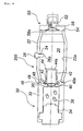
- Fig. 1 is a sectional view of an inflator in the axial direction thereof.
- An inflator 10 comprises a pressurized medium chamber 20, a gas generator 30 and a diffuser portion 50.
- the pressurized medium chamber 20 has an outer shell formed by a cylindrical pressurized medium chamber housing 22 and it is charged with a pressurized medium comprising a mixture of argon and helium. Since the pressurized medium chamber housing 22 is made symmetrical in the axial direction and a radial direction thereof, it is unnecessary to adjust the orientation in the axial and radial directions at a time of assembling.
- a charging hole 24 of a pressurized medium is formed on a side surface of the pressurized medium chamber housing 22, and it is closed by a pin 26 after the pressurized medium is charged.
- a distal end portion 26a of the pin 26 protrudes into the pressurized medium chamber 20, and the protruding portion thereof has such a length that combustion gas flow of a gas generating agent strikes against the protruding portion.
- combustion gas can strike against the pin 26 to have combustion residues adhered to the pin 26.
- the pin 26 can be extended until the distal end portion 26a thereof abuts against the opposite wall surface 22a.
- the gas generator 30 includes an ignition means (an electrical type igniter) 34 and a gas generating agent 36 accommodated in a gas generator housing 32, and it is connected to one end of the pressurized medium chamber 20.
- the gas generator housing 32 and the pressurized medium chamber housing 22 are connected at a connecting portion 49 by resistance-welding.
- the ignition means 34 is connected to an external power source via a connector and a lead wire.
- the gas generating agent 36 can comprises, for example, 34 mass% of nitroguanidine as a fuel, 56 mass% of strontium nitrate as an oxidizing agent, and 10 mass% of sodium carboxymethylcellulose as a bonding agent (a discharged gas temperature: 700 to 1630°C).
- a combustion residue generated when the gas generating agent 36 of the above composition is burnt is strontium oxide (melting point: 2430°C). For this reason, the combustion residue is solidified to be massive (slag-like) without being melted.
- a first communication hole 38 between the pressurized medium chamber 20 and the gas generator 30 is closed by a first rupturable plate 40 transformed into a bowl-like shape due to a pressure of the pressurized medium, and the interior of the gas generator 30 is maintained in the normal pressure.
- the first rupturable plate 40 is resistance-welded to the gas generator housing 32 at a peripheral edge portion 40a.
- a cap 44 having gas ejecting holes 42 is covered over the first rupturable plate 40 from the pressurized medium chamber 20 side.
- the cap 44 is attached to cover the first rupturable plate 40, so that combustion gas generated by combustion of the gas generating agent 36 is always ejected from the gas ejecting holes 42 via the cap 44.
- the cap 44 has a flange portion 46 formed by folding an opening peripheral edge portion outwardly, and it is fixed by crimping a portion (a crimping portion) 48 of the gas generator housing 32 at the flange portion 46.
- a diffuser portion 50 having gas discharging holes 52 for discharging the pressurized medium and the combustion gas is connected to the other end side of the pressurized medium chamber 20, and the diffuser portion 50 and the pressurized medium chamber housing 22 is resistance-welded to each other at a connecting portion 54.
- a filter made of wire mesh can be disposed inside the diffuser portion 50 in order to arrest the combustion residue, if required.
- a second communication hole 56 between the pressurized medium chamber 20 and the diffuser portion 50 is closed by a second rupturable plate 58 transformed into a bowl-like shape due to pressure of the pressurized medium, and the interior of the diffuser portion 50 is maintained in the normal pressure.
- the second rupturable plate 58 is resistance-welded to the diffuser portion 50 at a peripheral edge portion 58a.
- the igniter 34 When an automobile receives the impact by a collision, the igniter 34 is actuated and ignited by the activation-signal outputting means to burn the gas generating agent 36, thereby generating a high temperature combustion gas. At this time, since the melting point of a combustion residue generated by combustion of the gas generating agent 36 is equal to or more than a discharging temperature of a gas generated from the gas generating agent 36, the combustion residue can hardly melt, being maintained solid.
- the first rupturable plate 40 is broken by a pressure rise inside the gas generator 30 due to the high temperature combustion gas, and combustion gas including a combustion residue flows into the cap 44 to be ejected from the gas ejecting holes 42.
- the combustion gas is cooled rapidly, so that the high temperature combustion residue is cooled and solidified and a combustion residue also adheres to an inner wall surface of an end surface 44a of the cap 44.
- the combustion gas ejected strikes against an inner wall 22a of the pressurized medium chamber housing 22, the combustion residue adheres to an inner wall surface and it can be hardly discharged out of the inflator 10. Incidentally, part of the remaining combustion residue adheres to the pin 26, too.
- the inflator 10 since the inflator 10 exhibits the above-described actions and effects (1) to (3), the combustion residue discharged into the air bag is largely suppressed by these mutual effects.
- the combustion residue discharged outside the inflator 10 was 700 mg, but it could be reduced to 200 mg with the structure shown in Fig. 1.
- the arresting performance of the combustion residue can be further increased.
- Reference numeral 62 denotes a gas ejecting hole
- reference numeral 68 denotes a flange portion
- the cap 64 can be fixed to the diffuser portion 50 by the flange portion 68 and the crimping portion 59.
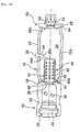
- FIG. 3 is a sectional view of an inflator in the axial direction thereof.
- An inflator 100 shown in Fig. 3 has almost the same structure as the inflator 10 shown in Fig. 1, and, in Fig 3, the same reference numerals as those in Fig. 1 denote the same parts.
- a difference in structure from Fig. 1 and a difference in advantageous effect due to the difference in structure will be explained below.
- an inner wall surface 22a of a pressurized medium chamber housing 22 has a groove with a depth of 0.2 mm formed continuously or discontinuously in the circumferential direction. With this, a combustion residue in combustion gas is caught and captured in the groove, an advantageous effect (4) can be exhibited in addition to the advantageous effects (1) to (3). Further, as shown in Fig. 2, an aspect in which a cap 64 is provided can be employed.
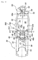
- FIG. 4 is a sectional view of an inflator in the axial direction thereof.
- An inflator 200 shown in Fig. 4 has almost the same structure as that of the inflator 10 shown in Fig. 1, and, in Fig. 4, the same reference numerals as those in Fig. 1 denote the same parts.
- a difference in structure from Fig. 1 and a difference in advantageous effect due to the difference in structure will be explained below.
- gas ejecting holes 42 are provided on a side surface of a cap 44 and they are opened to eject combustion gas towards the gas generator 30.
- combustion gas ejected from the gas ejecting holes 42 strikes against a crimped portion 48 and its vicinities before it strikes against the inner wall surface 22a of the pressurized medium chamber housing 22, and thereby, an advantageous effect (5) can be exhibited in addition to the advantageous effects (1) to (3).
- the advantageous effect (4) can be further exhibited.
- the aspect in which the cap 64 is provided can be employed, and the cap 44 of the other embodiment can be used instead of the cap 64.
- FIG. 5 is a perspective view and a plan view of a cap of one embodiment
- Fig. 6 is a perspective view and a plan view of a cap of another embodiment
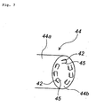
- Fig. 7 is a perspective view of a cap of another embodiment.
- a cap 44 shown in Fig. 5 to Fig. 7 can be disposed into the inflators 10, 100 and 200 shown in Fig. 1, Fig. 3 and Fig. 4 respectively, and, in the inflator shown in Fig. 2, the cap 64 can be in the shapes shown in Fig. 5 to Fig. 7.
- gas ejecting holes 42 are provided on a side surface of the cap 44a, and a member (restricting member) 45 for circumferentially restricting an ejecting direction of combustion gas from the gas ejecting holes 42.
- the restricting member 45 is formed in a L-letter shape in plan view. Incidentally, the orientation of the restricting member 45 may be a different direction from that in Fig. 5.
- combustion gas ejected from the gas ejecting hole 42 is ejected in the direction along the circumferential surface of the cap 44 to form an eddy, so that the advantageous effect (5) can be exhibited in addition to the advantageous effects (1) to (3) .
- the advantageous effect (4) can be further exhibited.
- the cap 44 shown in Fig. 6 is provided with flat plate-shaped restricting members 45 instead of the L-letter-shaped restricting members 45 shown in Fig. 5, and the same advantageous effect as those in Fig. 5 can be obtained.
- the cap 44 shown in Fig. 7 is provided on its end surface 44b with gas ejecting holes 42, and members (restricting members) 45 for circumferentially restricting an ejected direction of combustion gas from the gas ejecting holes 42.
- the restricting member 45 can be formed in the same shape as shown in Fig. 5 or Fig. 6.
- An inflator using the cap 44 shown in Fig. 7 can obtain the same advantageous effects as those in Fig. 5 and Fig. 6.
- FIG. 8 is a sectional view of an inflator in the axial direction.
- An inflator 300 shown in Fig. 8 has almost the same structure as that of the inflator 10 shown in Fig. 1, and, in Fig. 8, the same reference numerals as these in Fig. 1 denote the same parts.
- a difference in structure from Fig. 1 and a difference in advantageous effect due to the difference in structure will be explained below.
- a cylindrical barrier member 310 is attached thereto.
- the barrier member 310 has a closed one end integrated with a end surface of the cap 44b and the other end opened, and it is formed such that a side wall 311 faces gas ejecting holes 42 provided on the side surface of the cap 44a with a distance.
- the aspect in which the cap 64 is provided can be employed, and further, the cap 44 of the other embodiment can be employed instead of the cap 64.
- the combustion gas ejected from the gas ejecting holes 42 strikes against an inner wall of a side wall 311 of the barrier member, and then, it moves from the opening.
- the advantageous effect (6) can be exhibited in addition to the advantageous effects (1) to (3).
- the advantageous effect (4) can be exhibited as well.
- Fig. 9 is a sectional view of an inflator in the axial direction.
- An inflator 400 shown in Fig. 9 has almost the same structure as that of the inflator 10 shown in Fig. 1, and, in Fig. 9, the same reference numerals as those in Fig. 1 denote the same parts.
- a difference in structure from Fig. 1 and a difference in advantageous effect due to the difference in structure will be explained below.
- a disk-like barrier member 410 is attached.
- the barrier member 410 is integrated with a end surface of the cap 44b and it is extended from the end surface of the cap 44b towards an inner wall surface 22a of the pressurized medium chamber housing 22.
- the aspect in which the cap 64 is provided can be employed, and further, the cap 44 of another embodiment can be used instead of the cap 64.
- Fig. 10 is a sectional view of an inflator in the axial direction.
- An inflator 500 shown in Fig. 10 has almost the same structure as that of the inflator 10 shown in Fig. 1, and, in Fig. 10, the same reference numerals as those in Fig. 1 denote the same parts.
- a difference in structure in Fig. 1 and a difference in advantageous effect due to the difference in structure will be explained below.
- a disk-like barrier member 510 is attached.
- the barrier member 510 is integrated with an end surface of the cap 44b, and it is extended from the end surface of the cap 44b towards the inner wall surface 22a of the pressurized medium chamber housing 20 so that a peripheral edge portion 511 abuts on the inner wall surface 22a.
- Gas passing ports 512 and restricting means 513 having similar shapes like those in Fig. 6 are provided in the peripheral edge portion 511.
- the aspect in which the cap 64 is provided can be employed and further, the cap 44 of another embodiment can be used instead of the cap 64.
- the inflator of the present invention can be applied to various inflators such as an air bag inflator for a driver side, an air bag inflator for a passenger side next to a driver, an air bag inflator for a side collision, an inflator for a curtain air bag, an inflator for a knee-bolster, an inflator for an inflatable seat belt, an inflator for a tubular system, an iflator for a pretensioner and the like.
- various inflators such as an air bag inflator for a driver side, an air bag inflator for a passenger side next to a driver, an air bag inflator for a side collision, an inflator for a curtain air bag, an inflator for a knee-bolster, an inflator for an inflatable seat belt, an inflator for a tubular system, an iflator for a pretensioner and the like.
- Fig. 1 is a sectional view of an inflator in the axial direction.
- An inflator 610 comprises a pressurized gas chamber 620, a gas generator 630 and a diffuser portion 650.
- the pressurized gas chamber 620 has an outer shell formed by a cylindrical pressurized gas chamber housing 622 and it is charged with pressurized gas comprising a mixture of argon and helium. Since the pressurized gas chamber housing 622 is made symmetrical in the axial direction and a radial direction thereof, it is unnecessary to adjust the orientation in the axial and radial directions at a time of assembling.
- a charging hole 624 of pressurized gas is formed on a side surface of the pressurized gas chamber housing 622, and it is closed by a pin 626 after the pressurized gas is charged.
- a distal end portion 626a of the pin 626 protrudes into the pressurized gas chamber 620, and the protruding portion thereof has such a length that combustion gas flow of a gas generating agent strikes against the protruding portion.
- combustion gas can strike against the pin 26 to have combustion residues adhered to the pin 626.
- the pin 626 can be extended until the distal end portion 626a thereof abuts against the opposite wall surface 622a.
- the gas generator 630 has an ignition means (an electrical type igniter) 634 accommodated in a gas generator housing 632 and a gas generating chamber 635 accommodating a gas generating agent 636, and it is connected to one end of the pressurized gas chamber 620.
- a retainer 639 is disposed inside the gas generating chamber 635.
- the gas generator housing 632 and the pressurized gas chamber housing 622 are connected at a connecting portion 649 by resistance-welding.
- the ignition means 634 is connected to an external power source via a connector and a lead wire.
- the gas generating agent 636 can comprises, for example, 34 mass% of nitroguanidine as a fuel, 56 mass% of strontium nitrate as an oxidizing agent, and 10 mass% of sodium carboxymethylcellulose as a bonding agent (a discharged gas temperature: 700 to 1630°C).
- a combustion residue generated when the gas generating agent 636 of the above composition is burnt is strontium oxide (melting point: 2430°C). For this reason, the combustion residue is solidified to be massive (slag-like) without being melted.
- a first communication hole 638 between the pressurized gas chamber 620 and the gas generator 630 is closed by a first rupturable plate 640, and the interior of the gas generator 630 is maintained in the normal pressure.
- the first rupturable plate 640 is resistance-welded to the gas generator housing 632 at a peripheral edge portion.
- a diffuser portion 650 having gas discharging ports 652 for discharging the pressurized gas and the combustion gas is connected to the other end side of the pressurized gas chamber 620, and the diffuser portion 650 and the pressurized gas chamber housing 622 are resistance-welded to each other at a connecting portion 654.
- the diffuser portion 650 and the gas generating chamber housing 622 are connected such that their central axes coincide with each other.
- the diffuser portion 650 is a cap-shaped one having a plurality of gas discharging ports 652 through which a gas passes, wherein a distance L between a closed end surface 651 and an gas discharging port nearest to the closed end surface 651 and a diameter D of the rupturable plate 658 (except for a welded peripheral edge portion) satisfy the following formula: L ⁇ D/2.
- the distance L is preferably 3 to 8 mm, more preferably 4 to 8 mm, and particularly preferably 5 to 8 mm.
- the diameter of a plurality of the gas discharging ports 652 is preferably 0.5 to 2 mm, and more preferably 0.5 to 1. 2 mm.
- the total opening area of a plurality of the gas discharging ports 652 is preferably 20 to 1000 mm 2 , and more preferably 100 to 500 mm 2 .
- a second communication hole 656 between the pressurized gas chamber 620 and the diffuser portion 650 is closed by a second rupturable plate 658, and the interior of the diffuser portion 650 is maintained in the normal pressure.
- the second rupturable plate 658 is resistance-welded to the diffuser portion 650 at its peripheral edge portion.
- the igniter 634 When an automobile receives the impact by a collision, the igniter 634 is actuated and ignited by the activation-signal outputting means to burn the gas generating agent 636, thereby generating a high temperature combustion gas. At this time, since the melting point of a combustion residue generated by combustion of the gas generating agent 636 is equal to or more than a discharging temperature of a gas generated from the gas generating agent 636, the combustion residue can hardly melt, being maintained solid.
- the first rupturable plate 640 is broken by a pressure rise inside the gas generator 630 due to the high temperature combustion gas, and combustion gas including a combustion residue flows into the pressurized gas chamber 620.
- the pressurized gas and the combustion gas are discharged from the gas discharging holes 652 via the second communication hole 656 to inflate an air bag.
- Fig. 12 is a sectional view of an inflator in the axial direction. Since the inflators shown in Fig. 12 and Fig. 11 are different from each other only in part of a structure of a diffuser portion, the same parts are attached with the same reference numerals and explanations thereof will be omitted.
- An inflator 700 shown in Fig. 12 is provided at a distal end portion of a diffuser portion 650 with a stud bolt 660 used at the time of mounting the inflator to a module case.
- the inflator 700 shown in Fig. 12 discharges a gas according to the same action as that of the inflator 600 shown in Fig. 11 and conducts the same operation.
- Fig. 13 is a sectional view of an inflator in the axial direction thereof.
- An inflator 10 comprises a pressurized gas chamber 20, a gas generator 30 and a diffuser portion 50.
- the pressurized gas chamber 20 has an outer shell formed by a cylindrical pressurized gas chamber housing 22 and it is charged with pressurized gas comprising a mixture of argon and helium. Since the pressurized gas chamber housing 22 is made symmetrical in the axial direction and a radial direction thereof, it is unnecessary to adjust the orientation in the axial and radial directions at a time of assembling.
- a charging hole 24 of pressurized gas is formed on a side surface of the pressurized gas chamber housing 22, and it is closed by a pin 26 after the pressurized gas is charged.
- a distal end portion 26a of the pin 26 protrudes into the pressurized gas chamber 20, and the protruding portion thereof has such a length that combustion gas flow of a gas generating agent strikes against the protruding portion.
- combustion gas can strike against the pin 26 to have combustion residues adhered to the pin 26.
- the pin 26 can be extended until the distal end portion 26a thereof abuts against the opposite wall surface 22a.
- the gas generator 30 includes an ignition means (an electrical type igniter) 34 and a gas generating agent 36 accommodated in a gas generator housing 32, and it is connected to one end of the pressurized gas chamber 20.
- the gas generator housing 32 and the pressurized gas chamber housing 22 are connected at a connecting portion 49 by resistance-welding.
- the ignition means 34 is connected to an external power source via a connector and a lead wire.
- the gas generating agent 36 can comprises, for example, 34 mass% of nitroguanidine as a fuel, 56 mass% of strontium nitrate as an oxidizing agent, and 10 mass% of sodium carboxymethylcellulose as a bonding agent (a discharged gas temperature: 700 to 1630°C).
- a combustion residue generated when the gas generating agent 36 of the above composition is burnt is strontium oxide (melting point: 2430°C). For this reason, the combustion residue is solidified to be massive (slag-like) without being melted.
- a first communication hole 38 between the pressurized gas chamber 20 and the gas generator 30 is closed by a first rupturable plate 40 in a bowl-like shape, and the interior of the gas generator 30 is maintained in the normal pressure.
- the first rupturable plate 40 is resistance-welded to the gas generator housing 32 at a peripheral edge portion 40a.
- a cap 44 having gas ejecting holes 42 is covered over the first rupturable plate 40 from the pressurized gas chamber 20 side.
- the cap 44 is attached to cover the first rupturable plate 40, so that combustion gas generated by combustion of the gas generating agent 36 is always ejected from the gas ejecting holes 42 via the cap 44.
- a distance L1 between a closed end surface 44b of the cap 44 and an gas ejecting hole 42 nearest to the closed end surface 44b and a diameter D1 of the rupturable plate 40 (except for a welded peripheral edge portion) satisfy the following formula: L1 ⁇ D1/2.
- the distance L1 is preferably 3 to 8 mm, more preferably 4 to 8 mm, and particularly preferably 5 to 8 mm.
- the diameter of a plurality of the gas ejecting holes 42 is preferably 0.5 to 2 mm, and more preferably 0.5 to 1.2 mm.
- the total opening area of a plurality of the gas ejecting holes 42 is preferably 20 to 1000 mm 2 , and more preferably 100 to 500 mm 2 .
- the cap 44 has a flange portion 46 formed by folding an opening peripheral edge portion outwardly, and it is fixed by crimping a portion (a crimping portion) 48 of the gas generator housing 32 at the flange portion 46.
- a diffuser portion 50 having gas discharging holes 52 for discharging the pressurized gas and the combustion gas is connected to the other end side of the pressurized gas chamber 20, and the diffuser portion 50 and the pressurized gas chamber housing 22 is resistance-welded to each other at a connecting portion 54.
- the diffuser portion 50 is a cap-shaped one having a plurality of gas discharging ports 52 through which a gas passes, wherein a distance L2 between a closed end surface 51 and an gas discharging port nearest to the closed end surface 51 and a diameter D2 of the rupturable plate 58 (except for a welded peripheral edge portion) satisfy the following formula: L2 ⁇ D2/2.
- the distance L2 is preferably 3 to 8 mm, more preferably 4 to 8 mm, and particularly preferably 5 to 8 mm.
- the diameter of a plurality of the gas discharging ports 52 is preferably 0.5 to 2 mm, and more preferably 0.5 to 1.2 mm.
- the total opening area of a plurality of the gas discharging ports 52 is preferably 20 to 1000 mm 2 , and more preferably 100 to 500 mm 2 .
- a second communication hole 56 between the pressurized gas chamber 20 and the diffuser portion 50 is closed by a second rupturable plate 58, and the interior of the diffuser portion 50 is maintained in the normal pressure.
- the second rupturable plate 58 is resistance-welded to the diffuser portion 50 at a peripheral edge portion 58a.
- the igniter 34 When an automobile receives the impact by a collision, the igniter 34 is actuated and ignited by the activation-signal outputting means to burn the gas generating agent 36, thereby generating a high temperature combustion gas. At this time, since the melting point of a combustion residue generated by combustion of the gas generating agent 36 is equal to or more than a discharging temperature of a gas generated from the gas generating agent 36, the combustion residue can hardly melt, being maintained solid.
- the first rupturable plate 40 is broken by a pressure rise inside the gas generator 30 due to the high temperature combustion gas, and combustion gas including a combustion residue flows into the cap 44 to be ejected from the gas ejecting holes 42.
- the pressurized gas flows out from the gas ejecting holes 42 after the pressurized gas strikes against the closed end surface 44b of the cap 44 to change its flow direction, so that foreign materials can easily remain at a pocket portion from the closed end surface 44b to the gas ejecting hole 42 nearest to the closed end surface 44b.
- the above-described action is enhanced by setting the depth (L1) of the pocket portion to the maximum length (D1/2) of the foreign material or more, the foreign materials can remain more easily in the pocket.
- the gas is discharged from the cap 44 to remove the foreign materials.
- the combustion gas is cooled rapidly, so that the high temperature combustion residue is cooled and solidified and a combustion residue also adheres to the closed end surface 44b of the cap 44. Further, the ejected combustion gas strikes against an inner wall 22a of the pressurized gas chamber housing 22, so that the combustion residue adheres to an inner wall surface and it can be hardly discharged out of the inflator 10. Incidentally, part of the remaining combustion residue adheres to the pin 26, too.
- the second rupturable plate 58 is broken by a pressure rise inside the pressurized gas chamber 20, and consequently, the pressurized gas and the combustion gas are discharged from the gas discharging holes 52 via the second communication hole 56 to inflate an air bag.
- the relationship of L2 ⁇ D2/2 is satisfied even in the diffuser portion 50, an action similar to that of the cap 44 can be conducted.
- the inflator 10 exhibits the above-described advantageous effects (IIa) to (IIc), (1) to (3), an amount of pieces of the rupturable plate or combustion residues discharged in the air bag is largely suppressed.
- combustion residues discharged outside the inflator 10 was 700 mg. However, it was reduced to 200 mg by employing the structure shown in Fig. 13.
- Fig. 14 is a sectional view of an inflator in the axial direction. Since the inflators shown in Fig. 14 and Fig. 13 have the same structure except that the inflator shown in Fig. 14 is further provided with a cap covering the second rupturable plate, so that the same elements are attached with the same reference numerals and explanations thereof will be omitted.
- a cap 64 having a gas outflow holes 62 covers a second rupturable plate 58 from the pressurized gas chamber 20 side.
- the cap 64 is attached to cover the second rupturable plate 58 so that combustion gas generated by combustion of a gas generating agent 36 always passes the cap 64 and flows into a diffuser portion 50 from the gas outflow holes 62.
- Reference numeral 62 denotes the gas outflow hole
- reference numeral 68 denotes a flange portion
- the cap 64 is fixed to the diffuser portion 50 by the flange portion 68 and crimping portion 59.
- the diameter of and the total opening area of a plurality of the gas outflow holes 62 can be made equal to those in the gas ejecting holes 42.
- the cap 44 and the diffuser portion 50 satisfy the relation of L1 ⁇ D1/2 and the relation of L2 ⁇ D2/2 like the inflator 10 shown in Fig. 13 and the cap 64 is further provided, so that the advantageous effects (IIa) to (IIc) are further enhanced.
- Fig. 15 is a sectional view of an inflator in the axial direction.
- An inflator 100 shown in Fig. 15 has almost the same structure as that of the inflator 10 shown in Fig. 13, and the same reference numerals as those in Fig. 13 denote the same parts in Fig. 15.
- a difference in structure from Fig. 13 and an advantageous effect due to the difference in structure will be explained below.
- an inner wall surface 22a of a pressurized gas chamber housing 22 has a groove with a depth of 0.2 mm formed continuously or discontinuously in the circumferential direction. For this reason, combustion residues in combustion gas is arrested in the groove, and thereby, an advantageous effect (4) can be exhibited in addition to the advantageous effects (1) to (3). Further, as shown in Fig. 14, an aspect in which a cap 64 is provided can be employed.
- cap 44 and the diffuser portion 50 satisfy the relation of L1 ⁇ D1/2 and the relation of L2 ⁇ D2/2 like the inflator 10 shown in Fig. 13, the advantageous effects (IIa) to (IIc) can be obtained.
- Fig. 16 is a sectional view of an inflator in the axial direction.
- An inflator 200 shown in Fig. 16 has almost the same structure as that of the inflator 10 shown in Fig. 13, and, in Fig. 16, the same reference numerals as those in Fig. 13 denote the same parts.
- a difference in structure from Fig. 13 and an advantageous effect due to the difference in structure will be explained below.
- gas ejecting holes 42 are provided on a side surface of a cap 44 and they are opened to eject combustion gas towards the gas generator 30. For this reason, the combustion gas ejected from the gas ejecting holes 42 strikes against a crimped portion 48 and its vicinities before it strikes against the inner wall surface 22a of the pressurized gas chamber housing 22, and thereby, an advantageous effect (5) can be exhibited in addition to the advantageous effects (1) to (3).
- the advantageous effect (4) can be further exhibited.
- the aspect in which the cap 64 is provided can be employed, and the cap 44 of another embodiment can be used instead of the cap 64.
- cap 44 and the diffuser portion 50 satisfy the relation of L1 ⁇ D1/2 and the relation of L2 ⁇ D2/2 like the inflator 10 shown in Fig. 13, the advantageous effects (IIa) to (IIc) can be obtained.
- FIG. 5 is a perspective view and a plan view of a cap of one embodiment
- Fig. 6 is a perspective view and a plan view of a cap of another embodiment
- Fig. 7 is a perspective view of a cap of another embodiment.
- a cap 44 shown in Fig. 5 to Fig. 7 can be disposed into the inflators 600, 700, 10, 100 and 200 shown in Fig. 11 to Fig. 16 respectively.
- gas ejecting holes 42 are provided on a side surface of the cap 44a, and a member (restricting member) 45 for circumferentially restricting an ejecting direction of combustion gas from the gas ejecting holes 42.
- the restricting member 45 is formed in a L-letter shape in plan view. Incidentally, the orientation of the restricting member 45 may be a different direction from that in Fig. 5.
- combustion gas ejected from the gas ejecting hole 42 is ejected in the direction along the circumferential surface of the cap 44 to form an eddy, so that the advantageous effect (5) can be exhibited in addition to the advantageous effects (1) to (3).
- the advantageous effect (4) can be further exhibited.
- the cap 44 shown in Fig. 7 is provided with flat plate-shaped restricting members 45 instead of the L-letter-shaped restricting members 45 shown in Fig. 5, and the same advantageous effect as those in Fig. 5 can be obtained.
- the cap 44 shown in Fig. 7 is provided on its end surface 44a with gas ejecting holes 42, and members (restricting members) 45 for circumferentially restricting an ejected direction of combustion gas from the gas ejecting holes 42.
- the restricting member 45 can be formed in the same shape as shown in Fig. 5 or Fig. 6.
- An inflator using the cap 44 shown in Fig. 7 can obtain the same advantageous effects as those in Fig. 5 and Fig. 6.
- the advantageous effects (IIa) to (IIc) can be obtained like the inflator 10 shown in Fig. 13.
- the caps 44 shown in Fig. 5 and Fig. 6 are used, pieces of the broken first rupturable plate 40 can hardly be discharged out through the gas ejecting holes 42 due to an action of the restricting members, and thereby an arresting effect is further improved.
- Fig. 10 is a sectional view of an inflator in the axial direction.
- An inflator 300 shown in Fig. 10 has almost the same structure as that of the inflator 10 shown in Fig. 13, and, in Fig.10, the same reference numerals as these in Fig.13 denote the same parts.
- a difference in structure from Fig. 13 and a difference in advantageous effect due to the difference in structure will be explained below.
- a cylindrical barrier member 310 is attached thereto.
- the barrier member 310 has a closed one end integrated with a end surface of the cap 44b and the other end opened, and it is formed such that a side wall 311 faces gas ejecting holes 42 provided on the side surface of the cap 44a with a distance.
- the aspect in which the cap 64 is provided can be employed, and further, the cap 44 of the other embodiment can be employed instead of the cap 64.
- the advantageous effect (6) can be exhibited in addition to the advantageous effects (1) to (3).
- the advantageous effect (4) can be exhibited as well.
- Fig. 11 is a sectional view of an inflator in the axial direction.
- An inflator 400 shown in Fig. 11 has almost the same structure as that of the inflator 10 shown in Fig. 13, and, in Fig. 11, the same reference numerals as those in Fig. 13 denote the same parts.
- a difference in structure from Fig. 13 and a difference in advantageous effect due to the difference in structure will be explained below.
- a disk-like barrier member 410 is attached.
- the barrier member 410 is integrated with a end surface of the cap 44b and it is extended from the end surface of the cap 44b towards an inner wall surface 22a of the pressurized gas chamber housing 22.
- the aspect in which the cap 64 is provided can be employed, and further, the cap 44 of another embodiment can be used instead of the cap 64.
- Fig. 12 is a sectional view of an inflator in the axial direction.
- An inflator 500 shown in Fig. 12 has almost the same structure as that of the inflator 10 shown in Fig. 13, and, in Fig. 12, the same reference numerals as those in Fig. 13 denote the same parts.
- a difference in structure in Fig. 13 and a difference in advantageous effect due to the difference in structure will be explained below.
- a disk-like barrier member 510 is attached.
- the barrier member 510 is integrated with an end surface of the cap 44b, and it is extended from the end surface of the cap 44b towards the inner wall surface 22a of the pressurized gas chamber housing 20 so that a peripheral edge portion 511 abuts on the inner wall surface 22a.
- Gas passing ports 512 and restricting means 513 having similar shapes like those in Fig. 8 are provided in the peripheral edge portion 511.
- the aspect in which the cap 64 is provided can be employed and further, the cap 44 of another embodiment can be used instead of the cap 64.
- the inflator of the present invention can be applied to various inflators such as an air bag inflator for a driver side, an air bag inflator for a passenger side next to a driver, an air bag inflator for a side collision, an inflator for a curtain air bag, an inflator for a knee-bolster, an inflator for an inflatable seat belt, an inflator for a tubular system, an iflator for a pretensioner and the like.
- various inflators such as an air bag inflator for a driver side, an air bag inflator for a passenger side next to a driver, an air bag inflator for a side collision, an inflator for a curtain air bag, an inflator for a knee-bolster, an inflator for an inflatable seat belt, an inflator for a tubular system, an iflator for a pretensioner and the like.
- FIG. 20 and Fig. 21 are cross sectional views of embodiments of the present invention.
- An inflator 10 shown in Fig. 20 and an inflator 100 shown in Fig. 21 have almost the same structure except that the axial size of the inflator 10 is shorter than that of the inflator 100 and these inflators are different from each other in structure of a diffuser portion.
- the inflator 10 comprises a pressurized gas chamber 20, a gas generator 30 and a diffuser 50, and outer diameters of these members are set to approximately the same.
- the pressurized gas chamber 20 has an outer shell formed by a cylindrical pressurized gas chamber housing 22 and it is charged with pressurized gas comprising a mixture of argon and helium, not including oxygen gas.
- the pressurized gas chamber housing 22 is symmetrical axially and radially, and outer diameters at both ends are reduced to about 22 mm relative to an outer diameter D (about 25 mm) at the central portion thereof. Since a length L of the pressurized gas housing 22 is set to about 50 to 250 mm, L/D is 1 to 10.
- the pressurized gas chamber housing 22 has such a shape, it is unnecessary to adjust the orientation of the pressurized gas chamber housing in the axial and radial directions at a time of assembling, and joining work of the gas generator 30 and the diffuser portion 50 effected by resistance-welding or the like can be facilitated.
- a charging hole 24 for pressurized gas is formed on a side surface of the pressurized gas chamber housing 22, and it is closed by a pin 26 after pressurized gas is charged.
- a distal end portion 26a of the pin 26 protrudes into the pressurized medium chamber 20, and the protruding portion thereof has such a length that combustion gas flow of a gas generating agent strikes against the protruding portion.
- combustion gas can strike against the pin 26 to have combustion residues adhered to the pin 26.
- the pin 26 can be extended until the distal end portion 26a thereof abuts against the opposite wall surface 22a.
- the gas generator 30 includes an ignition means (an electrical type igniter) 34 and a gas generating agent 36 accommodated in a gas generator housing 32, and it is connected to one end of the pressurized gas chamber 20.
- the inflator 10 is fixed by crimping the part 35 of the gas generator housing 35.
- the gas generator housing 32 and the pressurized gas chamber housing 22 are connected at a connecting portion 49 by resistance-welding.
- the ignition means 34 is connected to an external power source via a connector and a lead wire.
- a first communication hole 38 between the pressurized gas chamber 20 and the gas generator 30 is closed by a first rupturable plate 40 transformed into a bowl-like shape due to a pressure of the pressurized gas, and the interior of the gas generator 30 is maintained in the normal pressure.
- the first rupturable plate 40 is resistance-welded to the gas generator housing 32 at a peripheral edge portion 40a.
- a cap 44 having gas ejecting holes 42 is covered over the first rupturable plate 40 from the pressurized gas chamber 20 side.
- the cap 44 is attached to cover the first rupturable plate 40, so that combustion gas generated by combustion of the gas generating agent 36 is always ejected from the gas ejecting holes 42 via the cap 44.
- the cap 44 has a flange portion 46 formed by folding an opening peripheral edge portion outwardly, and it is fixed by crimping a portion (a crimping portion) 48 of the gas generator housing 32 at the flange portion 46.
- a diffuser portion 50 having gas discharging holes 52 for discharging the pressurized gas and the combustion gas is connected to the other end side of the pressurized gas chamber 20, and the diffuser portion 50 and the pressurized gas chamber housing 22 is resistance-welded to each other at a connecting portion 54.
- a filter made of wire mesh can be disposed inside the diffuser portion 50 in order to arrest the combustion residue, if required.
- a second communication hole 56 between the pressurized gas chamber 20 and the diffuser portion 50 is closed by a second rupturable plate 58 transformed into a bowl-like shape due to pressure of the pressurized gas, and the interior of the diffuser portion 50 is maintained in the normal pressure.
- the second rupturable plate 58 is resistance-welded to the diffuser portion 50 at a peripheral edge portion 58a.
- Pressurized gas comprising a mixture of argon and helium, but not including oxygen gas is charged in a gas generator 20 under a charging pressure of 30,000 to 67,000 kPa.
- a ratio of an amount (mole number) of pressurized gas (A1) and an amount (mole number) of a gas generated by combustion of a gas generating agent (A2), A1/A2 1 to 20;
- a ratio of a mass of pressurized gas (B1) and a mass of a gas generating agent (B2), B1/B2 1 to 20;
- a ratio of an amount (mole number) of pressurized gas (A1) and a total surface opening (cm 2 ) of a gas generating agent (C), A1/C 0.004 to 0.05 mole/cm 2 ;
- a ratio of a total surface area (cm 2 ) of a gas generating agent (C) and a total area (cm 2 ) of gas discharging holes (D), C/D is 0.5 to 4;
- the igniter 34 When an automobile receives the impact by collision, the igniter 34 is activated and ignited upon receiving an actuation signal from a control unit to burn the gas generating agent 36, and thereby, combustion gas with a high temperature is generated.
- the first rupturable plate 40 is broken by a pressure rise inside the gas generator 30 due to the high temperature combustion gas, and combustion gas including a combustion residue flows into the cap 44 to be ejected from the gas ejecting holes 42.
- the combustion gas is cooled rapidly, so that the high temperature combustion residue is cooled and solidified and a combustion residue also adheres to an inner wall surface of an end surface 44a of the cap 44.
- the combustion gas ejected strikes against an inner wall 22a of the pressurized gas chamber housing 22, the combustion residue adheres to an inner wall surface and it can be hardly discharged out of the inflator 10. Incidentally, part of the remaining combustion residue adheres to the pin 26, too.
- the pressurized gas and the combustion gas are discharged from the gas discharging holes 52 via the second communication hole 56 to inflate an air bag.
- the inflator 10 is provided with the above-described requirements (1) to (6), or preferably (1) to (8), the internal pressure in the inflator is controlled not to rise excessively when the gas generating agent is burnt, even with the high pressurized-gas charging pressure of 30, 000 to 67, 000 kPa.
- the air bag can be inflated within an optimal time for protecting an occupant (generally, which is considered to be 10 to 30 msec).
- an internal pressure of the inflator when the gas generating agent is burnt can be controlled suitably, and thereby, the size of the inflator can be made small to downsize of the inflator while the charged amount of the pressurized gas is maintained to be equal to that in the prior art, that is, an amount of the pressurized gas for inflating the air bag is secured. And, as the result of downsizing the inflator, even when the charging pressure of the pressurized gas rises, an internal pressure of the inflator at an actuation can be controlled suitably.
- the inflators of the present invention can be applied to various inflators such as an air bag inflator for a driver side, an air bag inflator for a passenger side next to a driver, an air bag inflator for a side collision, an inflator for a curtain air bag, an inflator for a knee-bolster, an inflator for an inflatable seat belt, an inflator for a tubular system, an inflator for a pretensioner and the like.
- various inflators such as an air bag inflator for a driver side, an air bag inflator for a passenger side next to a driver, an air bag inflator for a side collision, an inflator for a curtain air bag, an inflator for a knee-bolster, an inflator for an inflatable seat belt, an inflator for a tubular system, an inflator for a pretensioner and the like.
- An inflator having the structure shown in Fig. 20 was produced. An entire length of the inflator was 110 mm, a length (L) of a pressurized gas chamber housing is 60 mm, an outer diameter (D) thereof is 25 mm, an thickness thereof is 2 mm (material: seamless steel pipe), and outer diameters of the other portions of the inflator were almost the same.
- the detail of the requirements (1) to (8) and the like are as follows:
- An inflator having the structure shown in Fig. 21 was produced.
- An entire length of the inflator was 280 mm, a length (L) of a pressurized gas chamber housing is 200 mm, an outer diameter (D) thereof is 25 mm, an thickness thereof is 2 mm (material: seamless steel pipe), and outer diameters of the other portions of the inflator were almost the same.
- the detail of the requirements (1) to (8) and the like are as follows:
Landscapes
- Chemical & Material Sciences (AREA)
- Engineering & Computer Science (AREA)
- Physics & Mathematics (AREA)
- Fluid Mechanics (AREA)
- Mechanical Engineering (AREA)
- Chemical Kinetics & Catalysis (AREA)
- Combustion & Propulsion (AREA)
- Organic Chemistry (AREA)
- Air Bags (AREA)
- Feeding, Discharge, Calcimining, Fusing, And Gas-Generation Devices (AREA)
Applications Claiming Priority (7)
| Application Number | Priority Date | Filing Date | Title |
|---|---|---|---|
| JP2001367283 | 2001-11-30 | ||
| JP2001367536 | 2001-11-30 | ||
| JP2002234431A JP2003226222A (ja) | 2001-11-30 | 2002-08-12 | インフレータ |
| JP2002258010 | 2002-09-03 | ||
| JP2002264946A JP3910897B2 (ja) | 2001-11-30 | 2002-09-11 | インフレータ |
| JP2002323737A JP2004149097A (ja) | 2001-11-30 | 2002-11-07 | インフレータ |
| EP02783660A EP1449724B1 (fr) | 2001-11-30 | 2002-11-27 | Gonfleur |
Related Parent Applications (2)
| Application Number | Title | Priority Date | Filing Date |
|---|---|---|---|
| EP02783660.0 Division | 2002-11-27 | ||
| EP02783660A Division EP1449724B1 (fr) | 2001-11-30 | 2002-11-27 | Gonfleur |
Publications (2)
| Publication Number | Publication Date |
|---|---|
| EP1867532A1 true EP1867532A1 (fr) | 2007-12-19 |
| EP1867532B1 EP1867532B1 (fr) | 2012-02-29 |
Family
ID=27555025
Family Applications (2)
| Application Number | Title | Priority Date | Filing Date |
|---|---|---|---|
| EP07018732A Expired - Lifetime EP1867532B1 (fr) | 2001-11-30 | 2002-11-27 | Génerateur de gaz |
| EP02783660A Expired - Lifetime EP1449724B1 (fr) | 2001-11-30 | 2002-11-27 | Gonfleur |
Family Applications After (1)
| Application Number | Title | Priority Date | Filing Date |
|---|---|---|---|
| EP02783660A Expired - Lifetime EP1449724B1 (fr) | 2001-11-30 | 2002-11-27 | Gonfleur |
Country Status (5)
| Country | Link |
|---|---|
| EP (2) | EP1867532B1 (fr) |
| CN (1) | CN1284693C (fr) |
| DE (1) | DE60226891D1 (fr) |
| TW (1) | TW200302178A (fr) |
| WO (1) | WO2003045739A1 (fr) |
Families Citing this family (13)
| Publication number | Priority date | Publication date | Assignee | Title |
|---|---|---|---|---|
| JP2005231571A (ja) * | 2004-02-23 | 2005-09-02 | Daicel Chem Ind Ltd | エアバッグ用ガス発生器 |
| DE102004040235A1 (de) * | 2004-08-13 | 2006-03-02 | Takata-Petri Ag | Beifahrerairbagmodul |
| JP2010012957A (ja) * | 2008-07-04 | 2010-01-21 | Daicel Chem Ind Ltd | インフレータ |
| FR2953008B1 (fr) * | 2009-11-25 | 2011-12-02 | Livbag | Generateur de gaz a gaz reactifs |
| US8714175B2 (en) | 2010-02-24 | 2014-05-06 | Applied Separations, Inc. | Pressure relief system for pressure vessels |
| JP5769943B2 (ja) * | 2010-10-01 | 2015-08-26 | 株式会社ダイセル | ガス発生器 |
| JP6054232B2 (ja) * | 2013-04-15 | 2016-12-27 | 株式会社ダイセル | ガス発生器 |
| CN107531208A (zh) * | 2015-04-24 | 2018-01-02 | 株式会社大赛璐 | 气体发生器 |
| DE112017000485B4 (de) * | 2016-01-25 | 2024-03-07 | Daicel Corporation | Gasgenerator |
| FR3053456B1 (fr) * | 2016-06-29 | 2018-06-29 | Autoliv Development Ab | Generateur de gaz |
| CN107662714A (zh) * | 2017-08-16 | 2018-02-06 | 北京航天长征飞行器研究所 | 一种高温燃气柔性扩散装置 |
| JP7211866B2 (ja) | 2019-03-25 | 2023-01-24 | 株式会社ダイセル | 金属組立体及びインフレータ |
| KR102583209B1 (ko) * | 2023-08-02 | 2023-09-26 | 국방과학연구소 | 팝업 장치 |
Citations (6)
| Publication number | Priority date | Publication date | Assignee | Title |
|---|---|---|---|---|
| EP0602862A1 (fr) * | 1992-12-14 | 1994-06-22 | Morton International, Inc. | Enlèvement des particules dans les générateurs de gaz de systèmes de retenue gonflables |
| EP0741064A2 (fr) * | 1995-05-02 | 1996-11-06 | Oea, Inc. | Procédé de fabrication d'un générateur hybride de gaz stocké dans un boîtier toroidal |
| US5615912A (en) * | 1995-10-05 | 1997-04-01 | Trw Vehicle Safety Systems Inc. | Inflator for air bag |
| US5836610A (en) * | 1994-05-31 | 1998-11-17 | Morton International, Inc. | Multiple level fluid fueled airbag inflator |
| WO1999015377A1 (fr) * | 1997-09-22 | 1999-04-01 | Autoliv Asp, Inc. | Dispositif de gonflage a emission adaptative avec selection de composition oxydante |
| WO1999015376A1 (fr) * | 1997-09-22 | 1999-04-01 | Autoliv Asp, Inc. | Gonfleur d'airbag sous pression contenant un fluide |
Family Cites Families (6)
| Publication number | Priority date | Publication date | Assignee | Title |
|---|---|---|---|---|
| FR2181354A5 (fr) | 1972-04-17 | 1973-11-30 | Eaton Corp | |
| US4018457A (en) | 1972-09-05 | 1977-04-19 | Olin Corporation | Inflating device for use with vehicle safety systems |
| IL115567A0 (en) | 1994-10-25 | 1996-01-19 | Oea Inc | Compact hybrid inflator |
| JP3137230B2 (ja) | 1995-09-11 | 2001-02-19 | オーイーエイ・インコーポレーテッド | 小型ハイブリッドインフレータ |
| US6189922B1 (en) | 1998-09-21 | 2001-02-20 | Autoliv Asp Inc. | Inflator with multiple initiators |
| JP2002166817A (ja) | 1999-10-01 | 2002-06-11 | Daicel Chem Ind Ltd | ハイブリッドインフレータ |
-
2002
- 2002-11-27 EP EP07018732A patent/EP1867532B1/fr not_active Expired - Lifetime
- 2002-11-27 DE DE60226891T patent/DE60226891D1/de not_active Expired - Lifetime
- 2002-11-27 EP EP02783660A patent/EP1449724B1/fr not_active Expired - Lifetime
- 2002-11-27 WO PCT/JP2002/012389 patent/WO2003045739A1/fr not_active Ceased
- 2002-11-27 CN CN 02825182 patent/CN1284693C/zh not_active Expired - Lifetime
- 2002-11-28 TW TW91134566A patent/TW200302178A/zh unknown
Patent Citations (6)
| Publication number | Priority date | Publication date | Assignee | Title |
|---|---|---|---|---|
| EP0602862A1 (fr) * | 1992-12-14 | 1994-06-22 | Morton International, Inc. | Enlèvement des particules dans les générateurs de gaz de systèmes de retenue gonflables |
| US5836610A (en) * | 1994-05-31 | 1998-11-17 | Morton International, Inc. | Multiple level fluid fueled airbag inflator |
| EP0741064A2 (fr) * | 1995-05-02 | 1996-11-06 | Oea, Inc. | Procédé de fabrication d'un générateur hybride de gaz stocké dans un boîtier toroidal |
| US5615912A (en) * | 1995-10-05 | 1997-04-01 | Trw Vehicle Safety Systems Inc. | Inflator for air bag |
| WO1999015377A1 (fr) * | 1997-09-22 | 1999-04-01 | Autoliv Asp, Inc. | Dispositif de gonflage a emission adaptative avec selection de composition oxydante |
| WO1999015376A1 (fr) * | 1997-09-22 | 1999-04-01 | Autoliv Asp, Inc. | Gonfleur d'airbag sous pression contenant un fluide |
Also Published As
| Publication number | Publication date |
|---|---|
| WO2003045739A1 (fr) | 2003-06-05 |
| EP1449724A1 (fr) | 2004-08-25 |
| TW200302178A (en) | 2003-08-01 |
| DE60226891D1 (de) | 2008-07-10 |
| EP1449724A4 (fr) | 2007-01-24 |
| EP1449724B1 (fr) | 2008-05-28 |
| CN1284693C (zh) | 2006-11-15 |
| EP1867532B1 (fr) | 2012-02-29 |
| CN1604864A (zh) | 2005-04-06 |
Similar Documents
| Publication | Publication Date | Title |
|---|---|---|
| US7134689B2 (en) | Inflator | |
| EP0800964B1 (fr) | Générateur de gaz pour coussin de sécurité gonflable et coussin de sécurité gonflable | |
| US6854395B2 (en) | Inflator for an air bag | |
| EP1867532B1 (fr) | Génerateur de gaz | |
| US6948737B2 (en) | Gas generator for air bag | |
| JP2003226222A (ja) | インフレータ | |
| US6808204B1 (en) | Hybrid inflator | |
| EP1327565B1 (fr) | Gonfleur hybride | |
| US20030071447A1 (en) | Multistage inflating-type hybrid inflator | |
| EP1415962B1 (fr) | Gonfleur pour coussin gonflable de securite | |
| US7044501B2 (en) | Inflator | |
| EP1459946B1 (fr) | Generateur de gaz destine a un coussin gonflable de securite | |
| US20040084884A1 (en) | Hybrid inflator | |
| US7780193B2 (en) | Gas generator | |
| US7275760B2 (en) | Multi-chamber gas generating system | |
| US6851709B2 (en) | Multistage-inflating type hybrid inflator | |
| CN100540513C (zh) | 充气器和气囊系统 | |
| US6908105B2 (en) | Gas generator for air bag | |
| JP2004149097A (ja) | インフレータ | |
| EP1514746A1 (fr) | Dispositif de gonflage | |
| EP1477374A1 (fr) | Systeme de gonflage hybride | |
| JP2001206189A (ja) | エアバッグ用ガス発生器及びエアバッグ装置 | |
| EP1422113B1 (fr) | Dispositif de gonflage hybride de type a gonflage a etapes multiples | |
| EP1419942B1 (fr) | Dispositif de gonflage de type a expansion par multiples paliers |
Legal Events
| Date | Code | Title | Description |
|---|---|---|---|
| PUAI | Public reference made under article 153(3) epc to a published international application that has entered the european phase |
Free format text: ORIGINAL CODE: 0009012 |
|
| AC | Divisional application: reference to earlier application |
Ref document number: 1449724 Country of ref document: EP Kind code of ref document: P |
|
| AK | Designated contracting states |
Kind code of ref document: A1 Designated state(s): CZ DE FR |
|
| RAP1 | Party data changed (applicant data changed or rights of an application transferred) |
Owner name: DAICEL CHEMICAL INDUSTRIES, LTD. |
|
| 17P | Request for examination filed |
Effective date: 20080303 |
|
| 17Q | First examination report despatched |
Effective date: 20080404 |
|
| AKX | Designation fees paid |
Designated state(s): DE FR |
|
| GRAP | Despatch of communication of intention to grant a patent |
Free format text: ORIGINAL CODE: EPIDOSNIGR1 |
|
| GRAS | Grant fee paid |
Free format text: ORIGINAL CODE: EPIDOSNIGR3 |
|
| GRAA | (expected) grant |
Free format text: ORIGINAL CODE: 0009210 |
|
| AC | Divisional application: reference to earlier application |
Ref document number: 1449724 Country of ref document: EP Kind code of ref document: P |
|
| AK | Designated contracting states |
Kind code of ref document: B1 Designated state(s): DE FR |
|
| REG | Reference to a national code |
Ref country code: DE Ref legal event code: R082 Ref document number: 60242326 Country of ref document: DE Representative=s name: GRUENECKER, KINKELDEY, STOCKMAIR & SCHWANHAEUS, DE Ref country code: DE Ref legal event code: R082 Ref document number: 60242326 Country of ref document: DE Representative=s name: GRUENECKER PATENT- UND RECHTSANWAELTE PARTG MB, DE |
|
| REG | Reference to a national code |
Ref country code: DE Ref legal event code: R096 Ref document number: 60242326 Country of ref document: DE Effective date: 20120426 |
|
| PLBE | No opposition filed within time limit |
Free format text: ORIGINAL CODE: 0009261 |
|
| STAA | Information on the status of an ep patent application or granted ep patent |
Free format text: STATUS: NO OPPOSITION FILED WITHIN TIME LIMIT |
|
| 26N | No opposition filed |
Effective date: 20121130 |
|
| REG | Reference to a national code |
Ref country code: DE Ref legal event code: R097 Ref document number: 60242326 Country of ref document: DE Effective date: 20121130 |
|
| REG | Reference to a national code |
Ref country code: FR Ref legal event code: ST Effective date: 20130731 |
|
| PG25 | Lapsed in a contracting state [announced via postgrant information from national office to epo] |
Ref country code: FR Free format text: LAPSE BECAUSE OF NON-PAYMENT OF DUE FEES Effective date: 20121130 |
|
| PGFP | Annual fee paid to national office [announced via postgrant information from national office to epo] |
Ref country code: DE Payment date: 20211118 Year of fee payment: 20 |
|
| REG | Reference to a national code |
Ref country code: DE Ref legal event code: R071 Ref document number: 60242326 Country of ref document: DE |