EP1867803A2 - Tragkörper für ein Geländer mit einer scheibenförmigen Füllung, insbesondere aus Glas - Google Patents
Tragkörper für ein Geländer mit einer scheibenförmigen Füllung, insbesondere aus Glas Download PDFInfo
- Publication number
- EP1867803A2 EP1867803A2 EP07010014A EP07010014A EP1867803A2 EP 1867803 A2 EP1867803 A2 EP 1867803A2 EP 07010014 A EP07010014 A EP 07010014A EP 07010014 A EP07010014 A EP 07010014A EP 1867803 A2 EP1867803 A2 EP 1867803A2
- Authority
- EP
- European Patent Office
- Prior art keywords
- shaped
- support body
- tab
- supporting body
- profile section
- Prior art date
- Legal status (The legal status is an assumption and is not a legal conclusion. Google has not performed a legal analysis and makes no representation as to the accuracy of the status listed.)
- Granted
Links
- 239000011521 glass Substances 0.000 title claims abstract description 4
- 239000000945 filler Substances 0.000 title 1
- 125000006850 spacer group Chemical group 0.000 claims description 12
- 229910000831 Steel Inorganic materials 0.000 claims description 8
- 239000010959 steel Substances 0.000 claims description 8
- XAGFODPZIPBFFR-UHFFFAOYSA-N aluminium Chemical compound [Al] XAGFODPZIPBFFR-UHFFFAOYSA-N 0.000 claims description 4
- 229910052782 aluminium Inorganic materials 0.000 claims description 4
- 238000005253 cladding Methods 0.000 claims description 3
- 230000004888 barrier function Effects 0.000 abstract 2
- 239000002184 metal Substances 0.000 abstract 1
- 239000005336 safety glass Substances 0.000 abstract 1
- 238000004519 manufacturing process Methods 0.000 description 3
- 238000010276 construction Methods 0.000 description 2
- 238000009434 installation Methods 0.000 description 2
- 230000015572 biosynthetic process Effects 0.000 description 1
- 150000001875 compounds Chemical class 0.000 description 1
- 238000004382 potting Methods 0.000 description 1
- 238000003466 welding Methods 0.000 description 1
Images
Classifications
-
- E—FIXED CONSTRUCTIONS
- E04—BUILDING
- E04F—FINISHING WORK ON BUILDINGS, e.g. STAIRS, FLOORS
- E04F11/00—Stairways, ramps, or like structures; Balustrades; Handrails
- E04F11/18—Balustrades; Handrails
- E04F11/181—Balustrades
- E04F11/1812—Details of anchoring to the wall or floor
-
- E—FIXED CONSTRUCTIONS
- E04—BUILDING
- E04F—FINISHING WORK ON BUILDINGS, e.g. STAIRS, FLOORS
- E04F11/00—Stairways, ramps, or like structures; Balustrades; Handrails
- E04F11/18—Balustrades; Handrails
- E04F11/181—Balustrades
- E04F11/1851—Filling panels, e.g. concrete, sheet metal panels
-
- E—FIXED CONSTRUCTIONS
- E04—BUILDING
- E04F—FINISHING WORK ON BUILDINGS, e.g. STAIRS, FLOORS
- E04F11/00—Stairways, ramps, or like structures; Balustrades; Handrails
- E04F11/18—Balustrades; Handrails
- E04F11/181—Balustrades
- E04F11/1851—Filling panels, e.g. concrete, sheet metal panels
- E04F11/1853—Glass panels
Definitions
- the invention relates to a supporting body for a railing with a disc-shaped filling, in particular of glass, according to the preamble of claim 1.
- Such support bodies are provided to clamp a lower edge portion of the disc-shaped filling in a cavity open on one side of a support body, which is bounded laterally by two parallel spaced in space, upright fixed webs.
- the filling of the clamped railing is fastened in the floor area of a building, for which purpose the support body is first to be mounted on the building.
- a handrail is attached at the top of the filling.
- Such a known supporting body is formed as a floor rail with upstanding webs, which are firmly connected to each other via a spacer arranged between them (EP 1 277 894 A1 ).
- a structural part of the support body may be provided with a base plate which is laterally welded at right angles to one of the two upstanding webs. From webs of the support body, flat grooves may be formed on top of each other on facing sides, which receive sections of flat cladding elements.
- the disc-shaped filling can be clamped by means of a pair of wedge-shaped bodies with adjoining, adjustable bevels be arranged between the inside of at least one of the two upstanding webs and the disc-shaped filling.
- a support strip may be placed on the spacer on which the disk-shaped filling is supported. Subsequently, the lower edge region of the disk-shaped filling can be cast in the support body.
- the disc-shaped filling can indeed be accurately aligned and held without disturbing exposure of the attachment in the ground area, but the welded construction of welded in particular by plug welding upright webs, which consist of steel, consuming in the production. Furthermore, the heavy weight of the steel structure can interfere.
- the entire support body is in each case adapted to the intended use on the building.
- the present invention is therefore an object of the invention to provide a supporting body for a railing with disc-shaped filling of the type mentioned, which avoids the disadvantages of the known welded construction of steel parts, so it can be easily formed and less time-consuming, easier to manufacture and to the particular application can be adjusted more freely.
- the support body as an extruded profile with the two parallel fixed webs and this holding at a distance distance section in one piece, in particular aluminum, pulled. It can be easily separated from larger extruded profile lengths according to the particular installation length required.
- the extruded profile is lightweight, especially when made of aluminum, so that it is easy to install can be handled and the structure is not significantly burdened.
- the embossed by the extruded appearance of the support body is also aesthetically pleasing.
- One of the extruded profile laterally of one of the two edgewise fixed webs integrally formed approximately C-shaped, outwardly open section can accommodate a vertical standing tab for mounting the support body to a structural part, which can be inserted into an open end of the extruded profile and with the Building part can be connected through a lateral opening in the C-shaped profile section therethrough.
- a vertical standing tab for mounting the support body to a structural part, which can be inserted into an open end of the extruded profile and with the Building part can be connected through a lateral opening in the C-shaped profile section therethrough.
- the extruded profile at the bottom i. under the one-sided open cavity or the spacer portion formed a laterally closed, in particular box-shaped hollow profile section.
- This laterally closed, in particular box-shaped hollow profile section forms a slight effective stiffening of the extruded profile without much additional manufacturing effort.
- the support body is in arrangement of the laterally closed, in particular box-shaped hollow profile section adjacent to a lower part of the C-shaped profile section, wherein aesthetically particularly appealing an underside of the box-shaped hollow profile section can pass smoothly into an underside of the C-shaped profile section.
- the drawn extruded profile can according to claim 3 from the upstanding webs of the support body formed on the top inside flat grooves , which can receive portions of flat cladding elements that cover the adjacent to the built-in support body environment.
- the support body is particularly advantageous supplemented according to claim 4 with an inserted in the C-shaped profile section upright tab, which has for attachment to the structural part of her laterally projecting foot plate, which extends through a lateral opening of the C-shaped profile section. It is thus possible to insert the tab with the base plate on an open end side of the extruded profile in the C-shaped profile section in order then to attach the protruding from the support base plate to the building part. It may instead be easy to install, first to mount the base plate with the suitably dimensioned tab on the building part in order then to postpone the C-shaped profile section of the extruded profile of the support body on the upright fixed tab and after fixing the upstanding tab in the C shaped profile section to clamp the filling of the railing.
- the horizontal base plate can be welded without problems with the upright tab before their connection to the C-shaped profile section.
- the upstanding tab can be secured in the C-shaped profile section in particular by screwing with the C-shaped profile section ,
- the upright bracket and possibly the base plate are made of steel and thus suitable to absorb large forces and moments at their junction with the base plate practically free of deformation and dissipate in the C-shaped profile section of the support body.
- 1 denotes a supporting body of a railing, not shown, and a disc-shaped filling, which can carry a handrail at the top.
- the support body is provided and dimensioned so that it can accommodate a lower edge portion of the disc-shaped filling.
- the support body drawn in one piece as an extruded aluminum profile has two upright standing parallel webs 2, 3 and a lower spacer section 4 between the webs, which are arranged in a U-shape, including the spacer section 4 are.
- the non-illustrated lower edge portion of a disc-shaped filling is held between the webs 2, 3, for which purpose preferably a pair of wedge-shaped body not shown serving with adjoining adjustable bevels, which are inserted on one side of the lower edge portion of the filling between this and one of the two webs , In this case, the lower edge portion of the filling can rest on the spacer portion 4 and be supported by this.
- the extruded profile has a box-shaped hollow profile section 5, the side walls preferably in the webs 2, 3 pass.
- the box-shaped hollow profile section 5 is suitable, above all, to absorb the forces and moments of the railing, that is to say the filling and the possibly loaded handrail, without disturbing distortion of the support body in order to derive it into an adjacent structural part, which in FIG is indicated in part.
- the structural part here consists essentially of concrete and includes an on-site vertical steel plate. 7
- an approximately C-shaped profile section 8 which forms an upper groove 9 and a lower groove 10 and laterally open at an opening 11.
- the C-shaped profile section 8 goes down into a bottom of the box-shaped hollow profile section 5 and thus is located at the bottom next to the box-shaped hollow profile section, beyond which it projects upwards.
- the extruded profile is suitable to divert forces and moments that are introduced by an inserted into the C-shaped profile section 8 upstanding tab 12 in the box-shaped hollow profile section 5, without significantly burdening the web 3 and bend.
- the upstanding tab 12 in the C-shaped profile section 8 allows prior to fixing a relative adjustability between her or the base plate and the C-shaped profile section 8 and in the fixed state, a defined force and moment transfer between the building part and the support body.
- the base plate 13 can, as shown in Figure 2 are screwed onto the building part 6, so that the support body 1 is maintained at a distance from the on-site vertical steel plate 7.
- the tab can be screwed by means of four screws with the C-shaped profile section 8. Three of the screws 14, 15, 16 can be seen in Figures 2 and 3.
- a screed plate 17 may serve, see Figure 1. Further, not shown in the drawing flat trim elements or sheets may optionally be suspended in the shallow grooves 18, 19, the top inside are formed from the webs 2, 3. The additional trim elements are intended primarily for aesthetic reasons.
- the support body 1 After mounting of the support body 1 to the building part, which can be done freely with the insertable into the C-shaped profile section tab 12 can be in the open-topped cavity 20 of the support body, which is bounded by the two webs 2, 3 and the spacer section 4 and the can record a non-illustrated elastic support strip, use the disc-shaped filling and set or clamp with the wedge-shaped bodies, not shown. Subsequently, the lower edge region of the filling can be potted with potting compound. The handrail can be mounted on the clamped filling so that the finished railing fulfills its intended function.
Landscapes
- Engineering & Computer Science (AREA)
- Architecture (AREA)
- Civil Engineering (AREA)
- Structural Engineering (AREA)
- Bridges Or Land Bridges (AREA)
- Steps, Ramps, And Handrails (AREA)
- Building Environments (AREA)
Abstract
Description
- Die Erfindung betrifft einen Tragkörper für ein Geländer mit einer scheibenförmigen Füllung, insbesondere aus Glas, nach dem Oberbegriff des Anspruchs 1.
- Derartige Tragkörper sind vorgesehen, um einen unteren Randabschnitt der scheibenförmigen Füllung in einem einseitig offenen Hohlraum eines Tragkörpers einzuspannen, der seitlich von zwei im lichten Abstand zueinander parallelen, hochkant feststehenden Stegen begrenzt ist. Mittels des Tragkörpers wird die Füllung des eingespannten Geländers in dem Bodenbereich eines Bauwerks befestigt, wozu zunächst der Tragkörper an dem Bauwerk zu montieren ist. An dem oberen Bereich der Füllung wird ein Handlauf angebracht.
- Ein derartiger bekannter Tragkörper ist als Bodenschiene mit hochkant stehenden Stegen ausgebildet, die über ein unten zwischen ihnen angeordnetes Distanzstück fest miteinander verbunden sind (
EP 1 277 894 A1 ). Zur Anbringung an einem Bauwerksteil kann der Tragkörper mit einer Fußplatte versehen sein, die seitlich rechtwinklig mit einem der beiden hochkant stehenden Stege verschweißt ist. Aus Stegen des Tragkörpers können oben auf einander zugewandten Seiten flache Nuten ausgeformt sein, die Abschnitte von flachen Verkleidungselementen aufnehmen. In einem solchen Tragkörper kann die scheibenförmige Füllung mittels eines Paars keilförmiger Körper mit aneinander liegenden, einstellbaren Schrägen eingespannt werden, die zwischen der Innenseite wenigstens eines der beiden hochkant stehenden Stege und der scheibenförmigen Füllung angeordnet sind. In dem durch die Stege und das Distanzstück auf drei Seiten umgrenzten Hohlraum kann ein Auflagestreifen auf das Distanzstück eingelegt sein, auf dem sich die scheibenförmige Füllung abstützt. Anschließend kann der untere Randbereich der scheibenförmigen Füllung in dem Tragkörper vergossen werden. Somit kann die scheibenförmige Füllung zwar ohne störende Exponierung der Anbringung im Bodenbereich exakt ausgerichtet und gehalten werden, jedoch ist die Schweißkonstruktion der insbesondere durch Lochschweißung verschweißten hochkant stehenden Stege, die aus Stahl bestehen, in der Herstellung aufwendig. Weiterhin kann das hohe Gewicht der Stahlkonstruktion stören. Der gesamte Tragkörper ist jeweils an den beabsichtigten Einsatzzweck an dem Bauwerk anzupassen. - Der vorliegenden Erfindung liegt daher die Aufgabe zugrunde, einen Tragkörper für ein Geländer mit scheibenförmiger Füllung der eingangs genannten Gattung zu schaffen, welches die Nachteile der bekannten Schweißkonstruktion aus Stahlteilen vermeidet, also leicht ausgebildet werden kann und weniger zeitaufwendig, einfacher hergestellt und an den jeweiligen Einsatzzweck freizügiger angepasst werden kann.
- Diese Aufgabe wird durch die Ausbildung des Tragkörpers mit den in Anspruch 1 angegebenen Merkmalen gelöst.
- Somit wird der Tragkörper als ein Strangpressprofil mit den beiden parallelen feststehenden Stegen und dem diese auf Abstand haltenden Distanzabschnitt einstückig, insbesondere aus Aluminium, gezogen. Er kann aus größeren Strangpressprofillängen einfach entsprechend der jeweils gewünschten Einbaulänge abgetrennt werden. Das Strangpressprofil ist, insbesondere wenn es aus Aluminium besteht, leicht, so dass es bei der Montage einfach gehandhabt werden kann und das Bauwerk nicht nennenswert belastet. Das durch das Strangpressprofil geprägte Erscheinungsbild des Tragkörpers ist auch ästhetisch ansprechend.
- Ein aus dem Strangpressprofil seitlich eines der beiden hochkant feststehenden Stege einstückig ausgeformter annähernd C-förmiger, nach außen offener Abschnitt kann zur Montage des Tragkörpers an einem Bauwerksteil eine hochkant stehende Lasche aufnehmen, die in eine offene Stirnseite des Strangpressprofils eingeschoben werden kann und die mit dem Bauwerksteil durch eine seitliche Öffnung in dem C-förmigen Profilabschnitt hindurch verbunden werden kann. Für verschiedene Einbauanforderungen kann es ausreichen, die in den C-förmigen Profilabschnitt einführbare Lasche anzupassen.
- Besonders vorteilhaft ist an dem Strangpressprofil unten, d.h. unter dem einseitig offenen Hohlraum bzw. dem Distanzabschnitt ein seitlich geschlossener, insbesondere kastenförmiger hohler Profilabschnitt ausgeformt. Dieser seitlich geschlossene, insbesondere kastenförmige hohle Profilabschnitt bildet eine leichte wirkungsvolle Versteifung des Strangpressprofils ohne großen zusätzlichen Herstellungsaufwand.
- Besonders formstabil ist der Tragkörper bei Anordnung des seitlich geschlossenen, insbesondere kastenförmigen hohlen Profilabschnitts neben einem unteren Teil des C-förmigen Profilabschnitts, wobei ästhetisch besonders ansprechend eine Unterseite des kastenförmigen hohlen Profilabschnitts stufenlos in eine Unterseite des C-förmigen Profilabschnitts übergehen kann.
- Das gezogene Strangpressprofil kann nach Anspruch 3 aus den hochkant stehenden Stegen des Tragkörpers oben innen ausgeformte flache Nuten aufweisen, die Abschnitte von flachen Verkleidungselementen aufnehmen können, welche die an den eingebauten Tragkörper angrenzende Umgebung abdecken.
- Der Tragkörper wird besonders vorteilhaft nach Anspruch 4 mit einer in dessen C-förmigen Profilabschnitt eingeschobenen hochkant stehenden Lasche ergänzt, die zur Befestigung an dem Bauwerksteil eine von ihr seitlich abstehende Fußplatte aufweist, die durch eine seitliche Öffnung des C-förmigen Profilabschnitts hindurchreicht. Es ist somit möglich, die Lasche mit der Fußplatte auf einer offenen Stirnseite des Strangpressprofils in den C-förmigen Profilabschnitt einzuschieben, um anschließend die von dem Tragkörper abstehende Fußplatte an dem Bauwerksteil anzubringen. Es kann statt dessen montagegünstig sein, zunächst die Fußplatte mit der geeignet dimensionierten Lasche an dem Bauwerksteil zu montieren, um anschließend den C-förmigen Profilabschnitt des Strangpressprofils des Tragkörpers auf die hochkant fest stehende Lasche aufzuschieben und nach Fixierung der hochkant stehenden Lasche in dem C-förmigen Profilabschnitt die Füllung des Geländers einzuspannen.
- Die horizontale Fußplatte kann mit der hochkant stehenden Lasche vor ihrer Verbindung mit dem C-förmigen Profilabschnitt unproblematisch verschweißt werden.
- Nach Einschieben der Lasche mit der Fußplatte in das C-förmige Profilteil oder umgekehrt Aufschieben des C-förmigen Profilteils auf die Lasche mit der montierten Fußplatte kann die hochkant stehende Lasche in dem C-förmigen Profilabschnitt insbesondere durch Verschraubung mit dem C-förmigen Profilabschnitt gesichert werden.
- Vorteilhaft sind die hochkant stehende Lasche und gegebenenfalls die Fußplatte aus Stahl gefertigt und somit geeignet, große Kräfte und Momente an ihrer Verbindungsstelle mit der Fußplatte praktisch verformungsfrei aufzunehmen und in den C-förmigen Profilabschnitt des Tragkörpers abzuleiten.
- Ein Ausführungsbeispiel der Erfindung wird im folgenden anhand einer Zeichnung mit vier Figuren erläutert. Es zeigen:
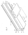
- Figur 1
- einen Tragkörper mit eingeschobener hochkant stehender Lasche, von der eine Fußplatte absteht, in einem weitgehend montierten Zustand in schaubildlicher Darstellung,
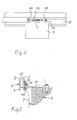
- Figur 2
- den Tragkörper mit hochkant stehender Lasche und Fußplatte in weitgehend eingebautem Zustand nach Figur 1 in einem Querschnitt,
- Figur 3
- eine Seitenansicht auf den Tragkörper mit Lasche und Fußplatte gemäß Figur 2 und
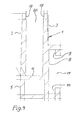
- Figur 4
- einen Querschnitt durch das Strangpressprofil des Tragkörpers in natürlicher Größe.
- In der Zeichnung ist mit 1 ein Tragkörper eines nicht dargestellten Geländers und einer scheibenförmigen Füllung bezeichnet, die oben einen Handlauf tragen kann. Der Tragkörper ist dazu vorgesehen und so dimensioniert, dass er einen unteren Randabschnitt der scheibenförmigen Füllung aufnehmen kann.
- Hierzu weist der einstückig als Strangpressprofil aus Aluminium gezogene Tragkörper zwei im festen lichten Abstand zueinander parallele, hochkant stehende Stege 2, 3 sowie einen unteren Distanzabschnitt 4 zwischen den Stegen auf, die unter Einschluss des Distanzabschnitts 4 U-förmig angeordnet sind. Der nicht dargestellte untere Randabschnitt einer scheibenförmigen Füllung wird zwischen den Stegen 2, 3 gehalten, wozu vorzugsweise ein nicht dargestelltes Paar keilförmiger Körper mit aneinander liegenden einstellbaren Schrägen dient, die auf einer Seite des unteren Randabschnitts der Füllung zwischen diese und einem der beiden Stege eingesetzt sind. Dabei kann der untere Randabschnitt der Füllung auf dem Distanzabschnitt 4 aufliegen und von diesem getragen werden.
- Unterhalb der Stege 2, 3 und des Distanzabschnitts 4 bzw. des einseitig offenen Hohlraums des Tragkörpers weist das Strangpressprofil einen kastenförmigen hohlen Profilabschnitt 5 auf, dessen Seitenwände bevorzugt in die Stege 2, 3 übergehen. Der kastenförmige hohle Profilabschnitt 5 ist geeignet, vor allem die Kräfte und Momente des Geländers, also der Füllung und des unter Umständen belasteten Handlaufs, ohne störende Verwindung des Tragkörpers aufzunehmen, um diese in ein benachbartes Bauwerksteil abzuleiten, welches in Figur 2 bei der Position 6 ausschnittsweise angedeutet ist. Das Bauwerksteil besteht hier im wesentlichen aus Beton und umfasst eine bauseitige vertikale Stahlplatte 7.
- Zur mittelbaren Verbindung mit dem Bauwerksteil ist weiterhin aus dem Strangpressprofil des Tragkörpers einstückig ein annähernd C-förmiger Profilabschnitt 8 ausgeformt, der eine obere Nut 9 und eine untere Nut 10 bildet und seitlich an einer Öffnung 11 offen ist. Der C-förmige Profilabschnitt 8 geht unten in einen Boden des kastenförmigen hohlen Profilabschnitts 5 über und befindet sich somit unten neben dem kastenförmigen hohlen Profilabschnitt, über den er nach oben hinausragt. Damit ist das Strangpressprofil geeignet, Kräfte und Momente, die durch eine in dem C-förmigen Profilabschnitt 8 eingeschobene hochkant stehende Lasche 12 eingeleitet werden, in den kastenförmigen hohlen Profilabschnitt 5 abzuleiten, ohne den Steg 3 erheblich zu belasten und zu verbiegen.
- Zur Montage des Tragkörpers 1 an dem Bauwerksteil 6 dient die in den C-förmigen Profilabschnitt 8 eingeschobene hochkant stehende Lasche 12, siehe insbesondere Figur 2, an die seitlich im Bereich der Öffnung 11 des C-förmigen Profilabschnitts 8 eine horizontale Fußplatte 13 angeschweißt ist.
- Die hochkant stehende Lasche 12 in dem C-förmigen Profilabschnitt 8 ermöglicht vor deren Fixierung eine relative Verstellbarkeit zwischen ihr bzw. der Fußplatte und dem C-förmigen Profilabschnitt 8 und im fixierten Zustand eine definierte Kraft- und Momentübertragung zwischen dem Bauwerksteil und dem Tragkörper.
- Die Fußplatte 13 kann, wie in Figur 2 dargestellt auf das Bauwerksteil 6 aufgeschraubt werden, so dass der Tragkörper 1 im Abstand zu der bauseitigen vertikalen Stahlplatte 7 erhalten wird. Um den Tragkörper gegenüber der Fußplatte 13 bzw. der Lasche 12 zu fixieren, kann die Lasche mittels vier Schrauben mit dem C-förmigen Profilabschnitt 8 verschraubt werden. Drei der Schrauben 14, 15, 16 sind in den Figuren 2 und 3 erkennbar.
- Zur partiellen Abdeckung der seitlichen Öffnung 11 des C-förmigen Profilabschnitts kann ein Estrichblech 17 dienen, siehe Figur 1. Weitere, in der Zeichnung nicht dargestellte flache Verkleidungselemente bzw. -bleche können optional in die flachen Nuten 18, 19 eingehängt werden, die oben innen aus den Stegen 2, 3 ausgeformt sind. Die zusätzlichen Verkleidungselemente sind hauptsächlich aus ästhetischen Gründen vorgesehen.
- Nach Montage des Tragkörpers 1 an dem Bauwerksteil, die mit der in den C-förmigen Profilabschnitt einschiebbaren Lasche 12 freizügig erfolgen kann, lässt sich in den oben offenen Hohlraum 20 des Tragkörpers, der von den beiden Stegen 2, 3 und dem Distanzabschnitt 4 begrenzt ist und der einen nicht dargestellten elastischen Auflagestreifen aufnehmen kann, die scheibenförmige Füllung einsetzen und mit den nicht dargestellten keilförmigen Körpern festlegen bzw. einspannen. Anschließend kann der untere Randbereich der Füllung mit Vergussmasse vergossen werden. Der Handlauf kann auf die eingespannte Füllung montiert werden, damit das damit fertiggestellte Geländer seine vorgesehene Gebrauchsfunktion erfüllt.
-
- 1
- Tragkörper
- 2
- Steg
- 3
- Steg
- 4
- Distanzabschnitt
- 5
- kastenförmiger hohler Profilabschnitt
- 6
- Bauwerksteil
- 7
- bauseitige vertikale Stahlplatte
- 8
- C-förmiger Profilabschnitt
- 9
- Nut
- 10
- Nut
- 11
- Öffnung
- 12
- Lasche
- 13
- Fußplatte
- 14
- Schraube
- 15
- Schraube
- 16
- Schraube
- 17
- Estrichblech
- 18
- flache Nut
- 19
- flache Nut
- 20
- Hohlraum
Claims (8)
- Tragkörper für ein Geländer mit einer scheibenförmigen Füllung, insbesondere aus Glas, deren unterer Randabschnitt in einem einseitig offenen Hohlraum (20) in dem Tragkörper (1) einspannbar ist, wobei der Hohlraum (20) seitlich von zwei im lichten Abstand zueinander parallelen hochkant feststehenden Stegen (2, 3) und unten von einem Distanzelement begrenzt ist,
dadurch gekennzeichnet,
dass der Tragkörper (1) ein Strangpressprofil ist, aus dem die beiden parallelen feststehenden Stege (2, 3) und zwischen diesen ein Distanzabschnitt (4) als Distanzelement einstückig ausgeformt sind, und
dass aus dem Strangpressprofil seitlich eines der hochkant feststehenden Stege (2, 3) ein annähernd C-förmiger, nach außen offener Profilabschnitt (8) ausgeformt ist, der geeignet ist, wenigstens eine hochkant stehende Lasche (12) aufzunehmen, die mit einem Bauwerksteil (6) verbindbar ist. - Tragkörper nach Anspruch 1,
dadurch gekennzeichnet,
dass an dem Strangpressprofil unter dem einseitig offenen Hohlraum (20) ein seitlich geschlossener, insbesondere kastenförmiger hohler Profilabschnitt (5) ausgeformt ist. - Tragkörper nach Anspruch 1 oder 2,
dadurch gekennzeichnet,
dass aus den hochkant stehenden Stegen (2, 3) des Tragkörpers (1) oben innen flache Nuten (18, 19) ausgeformt sind, die geeignet sind, Abschnitte von flachen Verkleidungselementen aufzunehmen. - Tragkörper nach einem der vorangehenden Ansprüche 1 bis 3 in Verbindung mit wenigstens einer seitlich abstehenden horizontalen Fußplatte (13),
dadurch gekennzeichnet,
dass die in den C-förmigen Profilabschnitt (8) des Tragkörpers (1) eingeschobene hochkant stehende Lasche (12) die von ihr seitlich abstehende Fußplatte (13) aufweist, die durch eine seitliche Öffnung (11) des C-förmigen Profilabschnitts (8) hindurchreicht. - Tragkörper nach Anspruch 4,
dadurch gekennzeichnet,
dass die horizontale Fußplatte (13) mit der hochkant stehenden Lasche (12) verschweißt ist. - Tragkörper nach Anspruch 4 oder 5,
dadurch gekennzeichnet,
dass die hochkant stehende Lasche (12) in dem C-förmigen Profilabschnitt (8) mit dem Tragkörper (1) verschraubt ist. - Tragkörper nach einem der vorangehenden Ansprüche,
dadurch gekennzeichnet,
dass das Strangpressprofil aus Aluminium besteht. - Tragkörper mit hochkant stehender Lasche nach einem der vorangehenden Ansprüche,
dadurch gekennzeichnet,
dass die hochkant feststehende Lasche (12) aus Stahl besteht.
Applications Claiming Priority (1)
| Application Number | Priority Date | Filing Date | Title |
|---|---|---|---|
| DE202006009323U DE202006009323U1 (de) | 2006-06-12 | 2006-06-12 | Tragkörper für ein Geländer mit einer scheibenförmigen Füllung |
Publications (3)
| Publication Number | Publication Date |
|---|---|
| EP1867803A2 true EP1867803A2 (de) | 2007-12-19 |
| EP1867803A3 EP1867803A3 (de) | 2009-01-14 |
| EP1867803B1 EP1867803B1 (de) | 2013-05-01 |
Family
ID=36934473
Family Applications (1)
| Application Number | Title | Priority Date | Filing Date |
|---|---|---|---|
| EP07010014.4A Not-in-force EP1867803B1 (de) | 2006-06-12 | 2007-05-19 | Tragkörper für ein Geländer mit einer scheibenförmigen Füllung, insbesondere aus Glas |
Country Status (4)
| Country | Link |
|---|---|
| EP (1) | EP1867803B1 (de) |
| DE (1) | DE202006009323U1 (de) |
| ES (1) | ES2406079T3 (de) |
| PT (1) | PT1867803E (de) |
Families Citing this family (3)
| Publication number | Priority date | Publication date | Assignee | Title |
|---|---|---|---|---|
| NL1035249C2 (nl) * | 2008-04-03 | 2009-10-06 | Pol Balkonhekken B V | Profielbalk. |
| CZ2008330A3 (cs) * | 2008-05-29 | 2009-05-27 | Integra Metal Systems, S. R. O. | Zábradlí pro ohrazení prostoru a profily tvorící toto zábradlí |
| CH704405B1 (de) | 2011-01-31 | 2014-06-30 | Beat Guhl | Befestigungsanordnung für Glasgeländer. |
Family Cites Families (5)
| Publication number | Priority date | Publication date | Assignee | Title |
|---|---|---|---|---|
| DE2135991A1 (de) * | 1971-07-19 | 1973-02-01 | Spiegelglas Und Gussglas Verka | Verfahren und vorrichtung fuer den einbau von freistehenden glasplatten |
| US6517056B2 (en) * | 2000-03-30 | 2003-02-11 | John D. Shepherd | Railing assembly |
| DE20111872U1 (de) * | 2001-07-18 | 2001-10-04 | Arnold GmbH, 61381 Friedrichsdorf | Eingespanntes Geländer |
| NZ525600A (en) * | 2003-05-01 | 2004-09-24 | Glass Relate Hardware Ltd | Base to support upright sheet using clamping action to retain the sheet |
| DE10338816B3 (de) * | 2003-08-21 | 2005-05-25 | Bernhard Feigl | Halterung für eine Platte, insbesondere für eine Glasscheibe |
-
2006
- 2006-06-12 DE DE202006009323U patent/DE202006009323U1/de not_active Expired - Lifetime
-
2007
- 2007-05-19 PT PT70100144T patent/PT1867803E/pt unknown
- 2007-05-19 ES ES07010014T patent/ES2406079T3/es active Active
- 2007-05-19 EP EP07010014.4A patent/EP1867803B1/de not_active Not-in-force
Also Published As
| Publication number | Publication date |
|---|---|
| EP1867803A3 (de) | 2009-01-14 |
| EP1867803B1 (de) | 2013-05-01 |
| DE202006009323U1 (de) | 2006-08-17 |
| ES2406079T3 (es) | 2013-06-05 |
| PT1867803E (pt) | 2013-06-12 |
Similar Documents
| Publication | Publication Date | Title |
|---|---|---|
| EP2354368B1 (de) | Befestigungsbügel für Wandisolierungen | |
| EP2460949B1 (de) | Scheiben-Geländer | |
| DE10344202A1 (de) | Solarmodulbefestigung, Verfahren zum Montieren einer Solaranlage und Anordnung aus einem Solarmodul und einem Solarmodulrahmen | |
| EP3260624B1 (de) | Scheiben-geländer | |
| EP2808143B1 (de) | Schalung zur Herstellung einer Treppe | |
| EP3781762B1 (de) | Vorrichtung und verfahren zur errichtung eines schwimmbeckens | |
| DE102004049595B3 (de) | Dachhaken | |
| DE102011000991A1 (de) | Wandhalterung für ein selbsttragendes, plattenförmiges Bauteil, insbesondere für ein Vordach, und Montageverfahren | |
| EP1867803B1 (de) | Tragkörper für ein Geländer mit einer scheibenförmigen Füllung, insbesondere aus Glas | |
| DE602004004692T2 (de) | Balkon oder ähnliches | |
| EP2649254A1 (de) | U-profil für die eingespannte lagerung einer geländerscheibe | |
| DE8418908U1 (de) | Haltevorrichtung mit halterung fuer sonnenkollektoren | |
| EP1785546A1 (de) | Konsolanker zur Fixierung einer Verblendung an einer Gebäudewand | |
| DE1880461U (de) | Hausbauplatte fuer haeuser aus vorgefertigten bauteilen. | |
| DE4204638A1 (de) | Vorrichtung zur schalldaemmung in raeumen | |
| DE102011001726B4 (de) | Modul zur Aufnahme einer Schiebetür, Schiebetürvorrichtung und Verfahren zur Montage einer Schiebetürvorrichtung | |
| EP3296475B1 (de) | Balkon und verfahren zur herstellung eines solchen balkons | |
| DE20305659U1 (de) | Ständerbauwerk, insbesondere aufgeständerter Vorsatzbalkon | |
| DE4134244C2 (de) | Befestigungsvorrichtung für eine Holz-Balkonbrüstung sowie zugehörige Balkonbrüstung | |
| DE10123319C2 (de) | Randabschluß an Gebäudedecken | |
| DE9207858U1 (de) | Dachrinne | |
| DE29607590U1 (de) | Bausatz zur nachträglichen Erstellung eines Balkons | |
| DE202025101742U1 (de) | Befestigungssystem, Anordnung, Verkleidungssystem und Tunnelbauwerk mit einem Befestigungssystem | |
| DE102022119007A1 (de) | Befestigungssystem für ein Fassadenelement und Verfahren zur Befestigung | |
| EP2716842A1 (de) | Befestigungssystem für die justierbare Montage von Verkleidungselementen |
Legal Events
| Date | Code | Title | Description |
|---|---|---|---|
| PUAI | Public reference made under article 153(3) epc to a published international application that has entered the european phase |
Free format text: ORIGINAL CODE: 0009012 |
|
| AK | Designated contracting states |
Kind code of ref document: A2 Designated state(s): AT BE BG CH CY CZ DE DK EE ES FI FR GB GR HU IE IS IT LI LT LU LV MC MT NL PL PT RO SE SI SK TR |
|
| AX | Request for extension of the european patent |
Extension state: AL BA HR MK YU |
|
| PUAL | Search report despatched |
Free format text: ORIGINAL CODE: 0009013 |
|
| AK | Designated contracting states |
Kind code of ref document: A3 Designated state(s): AT BE BG CH CY CZ DE DK EE ES FI FR GB GR HU IE IS IT LI LT LU LV MC MT NL PL PT RO SE SI SK TR |
|
| AX | Request for extension of the european patent |
Extension state: AL BA HR MK RS |
|
| 17P | Request for examination filed |
Effective date: 20090708 |
|
| AKX | Designation fees paid |
Designated state(s): AT BE BG CH CY CZ DE DK EE ES FI FR GB GR HU IE IS IT LI LT LU LV MC MT NL PL PT RO SE SI SK TR |
|
| GRAP | Despatch of communication of intention to grant a patent |
Free format text: ORIGINAL CODE: EPIDOSNIGR1 |
|
| GRAS | Grant fee paid |
Free format text: ORIGINAL CODE: EPIDOSNIGR3 |
|
| GRAA | (expected) grant |
Free format text: ORIGINAL CODE: 0009210 |
|
| AK | Designated contracting states |
Kind code of ref document: B1 Designated state(s): AT BE BG CH CY CZ DE DK EE ES FI FR GB GR HU IE IS IT LI LT LU LV MC MT NL PL PT RO SE SI SK TR |
|
| REG | Reference to a national code |
Ref country code: GB Ref legal event code: FG4D Free format text: NOT ENGLISH |
|
| REG | Reference to a national code |
Ref country code: AT Ref legal event code: REF Ref document number: 610050 Country of ref document: AT Kind code of ref document: T Effective date: 20130515 Ref country code: CH Ref legal event code: EP Ref country code: CH Ref legal event code: NV Representative=s name: BOHEST AG, CH |
|
| REG | Reference to a national code |
Ref country code: IE Ref legal event code: FG4D Free format text: LANGUAGE OF EP DOCUMENT: GERMAN |
|
| REG | Reference to a national code |
Ref country code: ES Ref legal event code: FG2A Ref document number: 2406079 Country of ref document: ES Kind code of ref document: T3 Effective date: 20130605 |
|
| REG | Reference to a national code |
Ref country code: PT Ref legal event code: SC4A Free format text: AVAILABILITY OF NATIONAL TRANSLATION Effective date: 20130604 |
|
| REG | Reference to a national code |
Ref country code: DE Ref legal event code: R096 Ref document number: 502007011679 Country of ref document: DE Effective date: 20130704 |
|
| REG | Reference to a national code |
Ref country code: NL Ref legal event code: T3 |
|
| REG | Reference to a national code |
Ref country code: LT Ref legal event code: MG4D |
|
| PG25 | Lapsed in a contracting state [announced via postgrant information from national office to epo] |
Ref country code: SE Free format text: LAPSE BECAUSE OF FAILURE TO SUBMIT A TRANSLATION OF THE DESCRIPTION OR TO PAY THE FEE WITHIN THE PRESCRIBED TIME-LIMIT Effective date: 20130501 Ref country code: IS Free format text: LAPSE BECAUSE OF FAILURE TO SUBMIT A TRANSLATION OF THE DESCRIPTION OR TO PAY THE FEE WITHIN THE PRESCRIBED TIME-LIMIT Effective date: 20130901 Ref country code: GR Free format text: LAPSE BECAUSE OF FAILURE TO SUBMIT A TRANSLATION OF THE DESCRIPTION OR TO PAY THE FEE WITHIN THE PRESCRIBED TIME-LIMIT Effective date: 20130802 Ref country code: SI Free format text: LAPSE BECAUSE OF FAILURE TO SUBMIT A TRANSLATION OF THE DESCRIPTION OR TO PAY THE FEE WITHIN THE PRESCRIBED TIME-LIMIT Effective date: 20130501 Ref country code: LT Free format text: LAPSE BECAUSE OF FAILURE TO SUBMIT A TRANSLATION OF THE DESCRIPTION OR TO PAY THE FEE WITHIN THE PRESCRIBED TIME-LIMIT Effective date: 20130501 Ref country code: FI Free format text: LAPSE BECAUSE OF FAILURE TO SUBMIT A TRANSLATION OF THE DESCRIPTION OR TO PAY THE FEE WITHIN THE PRESCRIBED TIME-LIMIT Effective date: 20130501 |
|
| PG25 | Lapsed in a contracting state [announced via postgrant information from national office to epo] |
Ref country code: BG Free format text: LAPSE BECAUSE OF FAILURE TO SUBMIT A TRANSLATION OF THE DESCRIPTION OR TO PAY THE FEE WITHIN THE PRESCRIBED TIME-LIMIT Effective date: 20130801 Ref country code: CY Free format text: LAPSE BECAUSE OF FAILURE TO SUBMIT A TRANSLATION OF THE DESCRIPTION OR TO PAY THE FEE WITHIN THE PRESCRIBED TIME-LIMIT Effective date: 20130501 Ref country code: PL Free format text: LAPSE BECAUSE OF FAILURE TO SUBMIT A TRANSLATION OF THE DESCRIPTION OR TO PAY THE FEE WITHIN THE PRESCRIBED TIME-LIMIT Effective date: 20130501 |
|
| PG25 | Lapsed in a contracting state [announced via postgrant information from national office to epo] |
Ref country code: LV Free format text: LAPSE BECAUSE OF FAILURE TO SUBMIT A TRANSLATION OF THE DESCRIPTION OR TO PAY THE FEE WITHIN THE PRESCRIBED TIME-LIMIT Effective date: 20130501 |
|
| PG25 | Lapsed in a contracting state [announced via postgrant information from national office to epo] |
Ref country code: EE Free format text: LAPSE BECAUSE OF FAILURE TO SUBMIT A TRANSLATION OF THE DESCRIPTION OR TO PAY THE FEE WITHIN THE PRESCRIBED TIME-LIMIT Effective date: 20130501 Ref country code: DK Free format text: LAPSE BECAUSE OF FAILURE TO SUBMIT A TRANSLATION OF THE DESCRIPTION OR TO PAY THE FEE WITHIN THE PRESCRIBED TIME-LIMIT Effective date: 20130501 Ref country code: MC Free format text: LAPSE BECAUSE OF FAILURE TO SUBMIT A TRANSLATION OF THE DESCRIPTION OR TO PAY THE FEE WITHIN THE PRESCRIBED TIME-LIMIT Effective date: 20130501 Ref country code: SK Free format text: LAPSE BECAUSE OF FAILURE TO SUBMIT A TRANSLATION OF THE DESCRIPTION OR TO PAY THE FEE WITHIN THE PRESCRIBED TIME-LIMIT Effective date: 20130501 |
|
| REG | Reference to a national code |
Ref country code: IE Ref legal event code: MM4A |
|
| PG25 | Lapsed in a contracting state [announced via postgrant information from national office to epo] |
Ref country code: IT Free format text: LAPSE BECAUSE OF FAILURE TO SUBMIT A TRANSLATION OF THE DESCRIPTION OR TO PAY THE FEE WITHIN THE PRESCRIBED TIME-LIMIT Effective date: 20130501 Ref country code: RO Free format text: LAPSE BECAUSE OF FAILURE TO SUBMIT A TRANSLATION OF THE DESCRIPTION OR TO PAY THE FEE WITHIN THE PRESCRIBED TIME-LIMIT Effective date: 20130501 |
|
| PLBE | No opposition filed within time limit |
Free format text: ORIGINAL CODE: 0009261 |
|
| STAA | Information on the status of an ep patent application or granted ep patent |
Free format text: STATUS: NO OPPOSITION FILED WITHIN TIME LIMIT |
|
| 26N | No opposition filed |
Effective date: 20140204 |
|
| PG25 | Lapsed in a contracting state [announced via postgrant information from national office to epo] |
Ref country code: IE Free format text: LAPSE BECAUSE OF NON-PAYMENT OF DUE FEES Effective date: 20130519 |
|
| REG | Reference to a national code |
Ref country code: DE Ref legal event code: R097 Ref document number: 502007011679 Country of ref document: DE Effective date: 20140204 |
|
| REG | Reference to a national code |
Ref country code: CH Ref legal event code: PCAR Free format text: NEW ADDRESS: HOLBEINSTRASSE 36-38, 4051 BASEL (CH) |
|
| PGFP | Annual fee paid to national office [announced via postgrant information from national office to epo] |
Ref country code: ES Payment date: 20140528 Year of fee payment: 8 Ref country code: CZ Payment date: 20140502 Year of fee payment: 8 Ref country code: NL Payment date: 20140524 Year of fee payment: 8 Ref country code: PT Payment date: 20130604 Year of fee payment: 8 |
|
| PG25 | Lapsed in a contracting state [announced via postgrant information from national office to epo] |
Ref country code: MT Free format text: LAPSE BECAUSE OF FAILURE TO SUBMIT A TRANSLATION OF THE DESCRIPTION OR TO PAY THE FEE WITHIN THE PRESCRIBED TIME-LIMIT Effective date: 20130501 |
|
| PG25 | Lapsed in a contracting state [announced via postgrant information from national office to epo] |
Ref country code: TR Free format text: LAPSE BECAUSE OF FAILURE TO SUBMIT A TRANSLATION OF THE DESCRIPTION OR TO PAY THE FEE WITHIN THE PRESCRIBED TIME-LIMIT Effective date: 20130501 |
|
| PG25 | Lapsed in a contracting state [announced via postgrant information from national office to epo] |
Ref country code: HU Free format text: LAPSE BECAUSE OF FAILURE TO SUBMIT A TRANSLATION OF THE DESCRIPTION OR TO PAY THE FEE WITHIN THE PRESCRIBED TIME-LIMIT; INVALID AB INITIO Effective date: 20070519 |
|
| REG | Reference to a national code |
Ref country code: PT Ref legal event code: MM4A Free format text: LAPSE DUE TO NON-PAYMENT OF FEES Effective date: 20151119 |
|
| REG | Reference to a national code |
Ref country code: NL Ref legal event code: MM Effective date: 20150601 |
|
| PG25 | Lapsed in a contracting state [announced via postgrant information from national office to epo] |
Ref country code: CZ Free format text: LAPSE BECAUSE OF NON-PAYMENT OF DUE FEES Effective date: 20150519 Ref country code: PT Free format text: LAPSE BECAUSE OF NON-PAYMENT OF DUE FEES Effective date: 20151119 |
|
| PG25 | Lapsed in a contracting state [announced via postgrant information from national office to epo] |
Ref country code: NL Free format text: LAPSE BECAUSE OF NON-PAYMENT OF DUE FEES Effective date: 20150601 |
|
| REG | Reference to a national code |
Ref country code: FR Ref legal event code: PLFP Year of fee payment: 10 |
|
| REG | Reference to a national code |
Ref country code: ES Ref legal event code: FD2A Effective date: 20161202 |
|
| PG25 | Lapsed in a contracting state [announced via postgrant information from national office to epo] |
Ref country code: ES Free format text: LAPSE BECAUSE OF NON-PAYMENT OF DUE FEES Effective date: 20150520 |
|
| REG | Reference to a national code |
Ref country code: FR Ref legal event code: PLFP Year of fee payment: 11 |
|
| REG | Reference to a national code |
Ref country code: DE Ref legal event code: R082 Ref document number: 502007011679 Country of ref document: DE Representative=s name: KEIL & SCHAAFHAUSEN PATENT- UND RECHTSANWAELTE, DE |
|
| REG | Reference to a national code |
Ref country code: FR Ref legal event code: PLFP Year of fee payment: 12 |
|
| PGFP | Annual fee paid to national office [announced via postgrant information from national office to epo] |
Ref country code: CH Payment date: 20180626 Year of fee payment: 12 Ref country code: LU Payment date: 20180625 Year of fee payment: 12 Ref country code: DE Payment date: 20180627 Year of fee payment: 12 |
|
| PGFP | Annual fee paid to national office [announced via postgrant information from national office to epo] |
Ref country code: AT Payment date: 20180620 Year of fee payment: 12 Ref country code: BE Payment date: 20180625 Year of fee payment: 12 Ref country code: FR Payment date: 20180625 Year of fee payment: 12 |
|
| PGFP | Annual fee paid to national office [announced via postgrant information from national office to epo] |
Ref country code: GB Payment date: 20180626 Year of fee payment: 12 |
|
| REG | Reference to a national code |
Ref country code: DE Ref legal event code: R119 Ref document number: 502007011679 Country of ref document: DE |
|
| REG | Reference to a national code |
Ref country code: CH Ref legal event code: PL |
|
| REG | Reference to a national code |
Ref country code: AT Ref legal event code: MM01 Ref document number: 610050 Country of ref document: AT Kind code of ref document: T Effective date: 20190519 |
|
| GBPC | Gb: european patent ceased through non-payment of renewal fee |
Effective date: 20190519 |
|
| PG25 | Lapsed in a contracting state [announced via postgrant information from national office to epo] |
Ref country code: AT Free format text: LAPSE BECAUSE OF NON-PAYMENT OF DUE FEES Effective date: 20190519 Ref country code: LI Free format text: LAPSE BECAUSE OF NON-PAYMENT OF DUE FEES Effective date: 20190531 Ref country code: CH Free format text: LAPSE BECAUSE OF NON-PAYMENT OF DUE FEES Effective date: 20190531 |
|
| REG | Reference to a national code |
Ref country code: BE Ref legal event code: MM Effective date: 20190531 |
|
| PG25 | Lapsed in a contracting state [announced via postgrant information from national office to epo] |
Ref country code: LU Free format text: LAPSE BECAUSE OF NON-PAYMENT OF DUE FEES Effective date: 20190519 |
|
| PG25 | Lapsed in a contracting state [announced via postgrant information from national office to epo] |
Ref country code: DE Free format text: LAPSE BECAUSE OF NON-PAYMENT OF DUE FEES Effective date: 20191203 Ref country code: GB Free format text: LAPSE BECAUSE OF NON-PAYMENT OF DUE FEES Effective date: 20190519 |
|
| PG25 | Lapsed in a contracting state [announced via postgrant information from national office to epo] |
Ref country code: BE Free format text: LAPSE BECAUSE OF NON-PAYMENT OF DUE FEES Effective date: 20190531 |
|
| PG25 | Lapsed in a contracting state [announced via postgrant information from national office to epo] |
Ref country code: FR Free format text: LAPSE BECAUSE OF NON-PAYMENT OF DUE FEES Effective date: 20190531 |