EP1867814B1 - Verstellbare Verriegelungsvorrichtung für eine Fahrzeughaube - Google Patents
Verstellbare Verriegelungsvorrichtung für eine Fahrzeughaube Download PDFInfo
- Publication number
- EP1867814B1 EP1867814B1 EP07300966A EP07300966A EP1867814B1 EP 1867814 B1 EP1867814 B1 EP 1867814B1 EP 07300966 A EP07300966 A EP 07300966A EP 07300966 A EP07300966 A EP 07300966A EP 1867814 B1 EP1867814 B1 EP 1867814B1
- Authority
- EP
- European Patent Office
- Prior art keywords
- bonnet
- vehicle
- axis
- adjustment means
- screw
- Prior art date
- Legal status (The legal status is an assumption and is not a legal conclusion. Google has not performed a legal analysis and makes no representation as to the accuracy of the status listed.)
- Active
Links
Images

Classifications
-
- E—FIXED CONSTRUCTIONS
- E05—LOCKS; KEYS; WINDOW OR DOOR FITTINGS; SAFES
- E05B—LOCKS; ACCESSORIES THEREFOR; HANDCUFFS
- E05B15/00—Other details of locks; Parts for engagement by bolts of fastening devices
- E05B15/02—Striking-plates; Keepers; Bolt staples; Escutcheons
- E05B15/0205—Striking-plates, keepers, staples
- E05B15/024—Striking-plates, keepers, staples adjustable
- E05B15/0245—Movable elements held by friction, cooperating teeth, or the like
-
- E—FIXED CONSTRUCTIONS
- E05—LOCKS; KEYS; WINDOW OR DOOR FITTINGS; SAFES
- E05B—LOCKS; ACCESSORIES THEREFOR; HANDCUFFS
- E05B77/00—Vehicle locks characterised by special functions or purposes
- E05B77/02—Vehicle locks characterised by special functions or purposes for accident situations
- E05B77/08—Arrangements for protection of pedestrians
-
- E—FIXED CONSTRUCTIONS
- E05—LOCKS; KEYS; WINDOW OR DOOR FITTINGS; SAFES
- E05B—LOCKS; ACCESSORIES THEREFOR; HANDCUFFS
- E05B85/00—Details of vehicle locks not provided for in groups E05B77/00 - E05B83/00
- E05B85/04—Strikers
- E05B85/045—Strikers for bifurcated bolts
Definitions
- the invention relates to the field of locking devices of a vehicle hood, as known from the document EP 1526046 A .
- the invention relates to a device for locking an adjustable vehicle hood according to at least one component of the space.
- the invention also relates to a locking device of an adjustable cover after mounting the vehicle.
- Vehicle hood locking devices are known whose positioning of the hood relative to the vehicle body is fixed, during assembly of the vehicle, by the height of the parts themselves and without subsequent adjustment possible.
- the Applicant has for example proposed solutions of this type, the device then comprising a lock in two parts, the first part being integral with the cover, the second part being integral with another bodywork element, the first and second parts being secured. from each other when the hood is in the closed state.
- the second part comprises a plate fixed to the bodywork element and arranged relative to the cover so that the distance, in the closed state, between the plate and the cover is determined during assembly and can not be adjusted thereafter .
- An object of the invention is to provide a hood locking device whose adjustment means are accessible by an individual after mounting the vehicle.
- Another object of the invention is to provide a hood locking device whose adjustment means are accessible by an individual from outside the vehicle.
- Another object of the present invention is to provide a cover locking device, the device being adjustable in at least one component of the space by means accessible to open or closed hood, and to adjust the positioning of the cover.
- a locking device of a vehicle hood comprising, a first portion secured to the cover, a second portion connected to the first portion and comprising a striker intended to be restrained when the hood is in the closed state, by a lock secured to a bodywork element, the relative position of the first and second parts being adjustable, at least in the direction of the opening / closing axis, by means of adjusting means accessible after mounting of the vehicle, characterized in that the second part comprises a fixed bridge of the striker and whose relative position in the direction of the axis of opening / closing and relative to the first part is adjustable by the adjustment means.
- an orthogonal reference mark XYZ formed by an axis X whose direction is parallel to the longitudinal axis of the vehicle is defined, a Y axis whose direction is parallel to the direction of the transverse axis of the vehicle. (depending on the width of the vehicle) and a Z axis whose direction is parallel to the vertical axis of the vehicle (depending on the height of the vehicle).
- the hood 2 of the vehicle is opened or closed in a rotational movement represented by arrows 21 and 22, respectively.
- the opening or closing action of the hood 2 enables to define an opening / closing axis 23 whose direction is substantially vertical, that is to say substantially parallel to the Z axis of the XYZ mark.
- the front part of the vehicle is referenced 24.
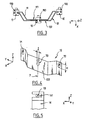
- the locking device 1 according to the invention of the hood 2 of the vehicle comprises a first portion 11 secured to the hood, a second portion comprising a bridge 12 integral with a keeper 13, and a third portion 14 formed by a lock integral with a body part 3.
- the first part 11 is fixed or welded to the means of tabs 111, 112 to the cover 2, but it can also be stamped in the cover 2.
- the striker 13 is fixed by means of welds 131, 132 on the support striker 12 and the lock 14 may be welded, or fixed by any other means to a body member 3 may for example be an upper rail of the vehicle.
- the first part 11 of the device is located inside the bridge 12 of the second part.
- the lock 14 provides a housing 141 in which the striker 13, substantially section circular, is inserted, lock which is also mobile in the YZ plane (the X axis is an axis of rotation of the lock).
- the parts 11, 12, 13 forming the first and second parts of the device 1 are therefore integral with the cover 2 while the lock 14 forming a third part of the device is integral with another bodywork element 3.
- the first part 11, which is integral with the cover 2 can translate, slide in the second part 12, 13 in the direction of the opening / closing axis 23.
- the adjustment means comprise at least one set 15, 150 screw / nut, and preferably three sets 15, 150, 16, 160, 17, 170 screws / nuts, as shown in FIG. figure 3 .
- the nuts 150, 160, 170 are fixed to the first part 11, preferably by welding, so that they remain in place on this first part 11 in the case of a disengagement of the screws 15, 16, 17 in the nut. respective.
- the distance d is then adjusted by adapting the relative position between the first part and the bridge, that is to say by adapting the distance D separating the first part 11 to the bridge 12 (adjustment in Z). More precisely, the distance D corresponds to the distance separating the bottom 113 of the first part 11 and the bottom 121 of the bridge 12.
- the screws must be accessible from the side of the device, and more precisely at walls 113, 122 of the first 11 and second parts 12, 13 respectively.
- These walls 113, 122 are located towards the front of the vehicle and extend substantially perpendicularly to the cover 2, so that screws are screwed / unscrewed about an axis of rotation substantially perpendicular to said walls 113, 122 , block / dislodge the possible translation between these parts.
- the screw / nut assemblies are arranged in the same plane.
- this plane is a plane extending substantially parallel to the XY plane, the XY plane being a horizontal plane.
- a first screw / nut assembly 15, 150 is intended to be inserted at an orifice 70 of a vertical wall 122 of the bridge 12.
- a second assembly 16, 160 screw / nut and a third assembly 17, 170 screws / nut are arranged symmetrically with respect to an axis 7 substantially parallel to the Z axis when the cover is in the closed state.
- the openings 70, 71, 72 of the bridge 12 have a height H, which defines the range of possible adjustment of the distance D and thus the distance d between the cover 2 and the lock 14.
- the orifices 70, 71, 72 of the bridge 12 also have a width I, dimensioned so that a play along the Y axis is possible between the bridge 1 2 and the first part 11.
- the first part 11 also provides orifices (not shown) vis-à-vis the orifices 70, 71, 72 of the bridge.
- These orifices of the first part 11 of the device can be of shape and dimensions substantially identical to the orifices 70, 71, 72, but may also have other shapes, being assumed to allow the previously described Y and Z adjustment.
- the device will preferably comprise three screw / nut assemblies to hold the assembly together, but two, arranged relative to one another in a direction substantially parallel to the direction of the Y axis, may be sufficient to avoid any rotation of the first and second parts relative to each other about the X axis.
- the action on the adjustment means, and more precisely on the screws, is performed easily because they are oriented to be accessible by an individual from outside the vehicle, and without the need to open the hood 2.
- the adjustment means are set when the hood is in the closed state.
- adjustment means are accessible by an individual after mounting the vehicle, and from outside the vehicle.
- the adjustment is therefore made from outside the vehicle when the hood is open.
- this embodiment has the advantage of making a precise adjustment, since it is directly related to the predetermined height of the hold.
- the distance d between the cover 2 of the lock 14 can be set in a range of values ranging from a few millimeters to a few centimeters.
- first and second parts can be interchanged, that is to say that the first part 11 of the device can be outside while the bridge 12 is inside of the first part 11.
- the bolt will be fixed to the trigger guard, and that the first part will have orifices corresponding to the orifices 70, 71, 72 presented in support of the figure 2 .
- the distance D separating the first portion 11 and the bridge 12 of the second part when the hood is in the closed state offers another feature.
- This feature is that of a shock absorber, for example during a shock with pedestrian.
- the present invention is not limited to the means described herein, but extends to any embodiment according to the claims.
Landscapes
- Superstructure Of Vehicle (AREA)
- Lock And Its Accessories (AREA)
Claims (10)
- Vorrichtung zur Verriegelung einer Fahrzeughaube (2), die einen ersten Teil (11), der fest mit der Haube verbunden ist, und einen zweiten Teil (12, 13) aufweist, der mit dem ersten Teil (11) verbunden ist und einen Schließhaken (13) aufweist, der dazu bestimmt ist, wenn die Haube (2) im geschlossenen Zustand ist, von einem Schloss (14) gehalten zu werden, das fest mit einem Karosserieelement (3) verbunden ist, wobei die relative Stellung des ersten (11) und zweiten Teils (12) zumindest in Richtung der Öffnungs-/Schließachse (23) durch Einstellmittel (15, 150) einstellbar ist, die nach dem Zusammenbau des Fahrzeugs zugänglich sind, dadurch gekennzeichnet, dass der zweite Teil (12, 13) einen Bügel (12) aufweist, der fest mit dem Schließhaken (13) verbunden ist und dessen relative Stellung in Richtung der Öffnungs-/Schließachse (23) und bezüglich des ersten Teils (11) durch die Einstellmittel einstellbar ist.
- Vorrichtung nach Anspruch 1, dadurch gekennzeichnet, dass die relative Stellung des ersten (11) und zweiten Teils (12, 13) außerdem von den Einstellmitteln (15, 150) in Richtung der Achse (Y) einstellbar ist, die gemäß der Breite des Fahrzeugs ausgerichtet ist.
- Vorrichtung nach einem der vorhergehenden Ansprüche, dadurch gekennzeichnet, dass die Einstellmittel (15, 150) einstellbar sind, wenn die Haube (2) im geschlossenen Zustand ist.
- Vorrichtung nach einem der vorhergehenden Ansprüche, dadurch gekennzeichnet, dass die Einstellmittel (15, 150) von einer Person von außerhalb des Fahrzeugs erreichbar sind, wenn die Haube (2) im geschlossenen Zustand ist und wenn der Stoßfänger nicht montiert ist.
- Vorrichtung nach einem der Ansprüche 1 bis 2, dadurch gekennzeichnet, dass sie einen Keil vorbestimmter Höhe aufweist, der zwischen dem ersten Teil (11) und dem Bügel (12) angeordnet ist.
- Vorrichtung nach einem der vorhergehenden Ansprüche, dadurch gekennzeichnet, dass die Einstellmittel mindestens eine Schraube/Mutter-Einheit (15, 150) aufweisen, wobei Wände (113, 122) des ersten Teils (11) und des zweiten Teils (12, 13), die sich im Wesentlichen lotrecht zur Haube (2) erstrecken, zwischen dem Schraubenkopf (15) und der Mutter (150) angeordnet sind.
- Vorrichtung nach Anspruch 6, dadurch gekennzeichnet, dass die Schraube (15) eine Drehachse im Wesentlichen lotrecht zu den Wänden (113, 122) hat, die zwischen dem Schraubenkopf (15) und der Mutter (150) angeordnet sind.
- Vorrichtung nach einem der Ansprüche 6 oder 7, dadurch gekennzeichnet, dass sie mindestens drei Schraube/Mutter-Einheiten (15, 16, 17, 150, 160, 170) aufweist, die in der gleichen Ebene angeordnet sind.
- Vorrichtung nach einem der vorhergehenden Ansprüche, dadurch gekennzeichnet, dass der Abstand (d), gemessen im geschlossenen Zustand der Haube und gemäß der Öffnungs-/Schließachse (23) der Haube (2), der die Haube (2) vom Schloss (14) trennt, in einem Bereich einstellbar ist, der von einigen Millimetern bis zu einigen Zentimetern reicht.
- Vorrichtung nach einem der vorhergehenden Ansprüche, dadurch gekennzeichnet, dass sie so eingerichtet ist, dass eine Annäherungsbewegung zwischen dem ersten Teil (11) und dem zweiten Teil (12, 13) in Richtung der Öffnungs-/Schließachse (23) und ausgehend von der relativen Stellung des ersten (11) und zweiten Teils (12, 13), wenn die Haube (2) im geschlossenen Zustand ist, im Fall eines Stoßes ausgeübt wird.
Applications Claiming Priority (1)
| Application Number | Priority Date | Filing Date | Title |
|---|---|---|---|
| FR0605187A FR2902132B1 (fr) | 2006-06-12 | 2006-06-12 | Dispositif de verrouillage reglable d'un capot de vehicule |
Publications (2)
| Publication Number | Publication Date |
|---|---|
| EP1867814A1 EP1867814A1 (de) | 2007-12-19 |
| EP1867814B1 true EP1867814B1 (de) | 2008-07-30 |
Family
ID=37814596
Family Applications (1)
| Application Number | Title | Priority Date | Filing Date |
|---|---|---|---|
| EP07300966A Active EP1867814B1 (de) | 2006-06-12 | 2007-04-20 | Verstellbare Verriegelungsvorrichtung für eine Fahrzeughaube |
Country Status (4)
| Country | Link |
|---|---|
| EP (1) | EP1867814B1 (de) |
| AT (1) | ATE403052T1 (de) |
| DE (1) | DE602007000051D1 (de) |
| FR (1) | FR2902132B1 (de) |
Families Citing this family (3)
| Publication number | Priority date | Publication date | Assignee | Title |
|---|---|---|---|---|
| CN109489993B (zh) * | 2018-12-30 | 2024-06-25 | 东风小康汽车有限公司重庆分公司 | 车辆引擎盖调节总成 |
| CN112706604A (zh) * | 2019-10-27 | 2021-04-27 | 孙希贤 | 一种动力机保护板 |
| FR3115553B1 (fr) | 2020-10-26 | 2023-10-20 | Psa Automobiles Sa | Dispositif de fixation de serrure a reglage de position, et ensemble comprenant le dispositif et la serrure |
Family Cites Families (5)
| Publication number | Priority date | Publication date | Assignee | Title |
|---|---|---|---|---|
| JPS54149129A (en) * | 1978-05-12 | 1979-11-22 | Nissan Motor Co Ltd | Lock striker |
| JPS60123682A (ja) * | 1983-12-08 | 1985-07-02 | 株式会社大井製作所 | 自動車用フ−ドロック装置 |
| DE19522220C2 (de) * | 1995-06-20 | 2002-11-14 | Opel Adam Ag | Schließvorrichtung |
| JP3956833B2 (ja) * | 2002-10-29 | 2007-08-08 | トヨタ車体株式会社 | エンジンフードのロック部構造 |
| FR2861115B1 (fr) * | 2003-10-16 | 2008-05-23 | Renault Sa | Serrure a absorption de choc pieton pour capot avant de vehicule automobile |
-
2006
- 2006-06-12 FR FR0605187A patent/FR2902132B1/fr not_active Expired - Fee Related
-
2007
- 2007-04-20 AT AT07300966T patent/ATE403052T1/de not_active IP Right Cessation
- 2007-04-20 EP EP07300966A patent/EP1867814B1/de active Active
- 2007-04-20 DE DE602007000051T patent/DE602007000051D1/de active Active
Also Published As
| Publication number | Publication date |
|---|---|
| EP1867814A1 (de) | 2007-12-19 |
| FR2902132B1 (fr) | 2008-08-08 |
| DE602007000051D1 (de) | 2008-09-11 |
| FR2902132A1 (fr) | 2007-12-14 |
| ATE403052T1 (de) | 2008-08-15 |
Similar Documents
| Publication | Publication Date | Title |
|---|---|---|
| EP3447218B1 (de) | Verriegelungssystem, das mit einem griff und einem versetzten trägheitssystem ausgestattet ist | |
| EP2914476B1 (de) | Vorrichtung zur befestigung zweier bauteile aneinander mit einem gleitenden positionierungselement | |
| EP1867814B1 (de) | Verstellbare Verriegelungsvorrichtung für eine Fahrzeughaube | |
| WO2018162146A1 (fr) | Agencement de maintien d'un bac de coffre a l'avant d'une structure de caise d'un vehicule automobile | |
| FR2876135A1 (fr) | Dispositif de commande du mecanisme d'ouverture d'un ouvrant de vehicule automobile, et procede de montage du dispositif | |
| EP2942237B1 (de) | Vorrichtung zur verankerung einer extremität einer dachreling für ein kraftfahrzeug, das mit längs-dachrelingen ausgestattet ist | |
| EP1616753B1 (de) | Beleuchtungseinrichtung für Kraftfahrzeuge mit erhöhter Sicherheit bei einem Aufprall | |
| EP1358084B9 (de) | Heckklappe eines personenkraftwagens mit stossfänger | |
| FR2915725A1 (fr) | Structure de vehicule comportant une traverse de planche de bord | |
| EP1213183B1 (de) | Rückblickspiegel und Befestigungssystem | |
| EP3254877B1 (de) | Innenverkleidung einer seitlichen schiebetür | |
| EP4101721B1 (de) | Kit zur montage einer verkleidungsplatte an einer karosserie eines transportfahrzeugs, karosserie und fahrzeug mit einem solchen kit und entsprechendes montageverfahren | |
| FR3099907A1 (fr) | Déflecteur aérodynamique arrière pour véhicule automobile | |
| EP4232663B1 (de) | Vorrichtung zur befestigung eines positionsverstellbaren schlosses und anordnung mit der vorrichtung und dem schloss | |
| EP1849664B1 (de) | Passive Sicherheitsvorrichtung für den Fall eines Zusammenstoßes eines Fußgängers mit einem Kraftfahrzeug und Fahrzeug, das eine solche Vorrichtung umfasst | |
| EP1244585B1 (de) | Befestigungsverfahren für einen kraftfahrzeugsflügel und vorrichtung für ein solches verfahren | |
| FR3010040A1 (fr) | Dispositif de positionnement geometrique d'une aile avant sur la structure avant de la caisse d'un vehicule automobile | |
| FR2921040A1 (fr) | Procede d'assemblage d'une peau de pare-chocs sur une caisse de vehicule automobile. | |
| FR2850945A1 (fr) | Structure de pied avant d'un vehicule automobile | |
| FR3111598A1 (fr) | Capot de support d’alarme | |
| FR2971565A1 (fr) | Systeme de fixation reglable formant entretoise. | |
| FR2963804A1 (fr) | Sous ensemble de fermeture d'un ouvrant de vehicule | |
| FR2931505A3 (fr) | Agencement de moyens de verrouillage sur une porte de coffre de vehicule automobile perfectionnes | |
| EP3233589B1 (de) | Diebstahlschutz für lenksäule in einem kraftfahrzeug | |
| FR3144940A1 (fr) | Volet arrière de coffre doté d’un becquet « flottant » |
Legal Events
| Date | Code | Title | Description |
|---|---|---|---|
| PUAI | Public reference made under article 153(3) epc to a published international application that has entered the european phase |
Free format text: ORIGINAL CODE: 0009012 |
|
| AK | Designated contracting states |
Kind code of ref document: A1 Designated state(s): AT BE BG CH CY CZ DE DK EE ES FI FR GB GR HU IE IS IT LI LT LU LV MC MT NL PL PT RO SE SI SK TR |
|
| AX | Request for extension of the european patent |
Extension state: AL BA HR MK YU |
|
| GRAP | Despatch of communication of intention to grant a patent |
Free format text: ORIGINAL CODE: EPIDOSNIGR1 |
|
| 17P | Request for examination filed |
Effective date: 20080104 |
|
| GRAS | Grant fee paid |
Free format text: ORIGINAL CODE: EPIDOSNIGR3 |
|
| GRAA | (expected) grant |
Free format text: ORIGINAL CODE: 0009210 |
|
| AK | Designated contracting states |
Kind code of ref document: B1 Designated state(s): AT BE BG CH CY CZ DE DK EE ES FI FR GB GR HU IE IS IT LI LT LU LV MC MT NL PL PT RO SE SI SK TR |
|
| REG | Reference to a national code |
Ref country code: GB Ref legal event code: FG4D Free format text: NOT ENGLISH |
|
| REG | Reference to a national code |
Ref country code: CH Ref legal event code: EP |
|
| AKX | Designation fees paid |
Designated state(s): AT BE BG CH CY CZ DE DK EE ES FI FR GB GR HU IE IS IT LI LT LU LV MC MT NL PL PT RO SE SI SK TR |
|
| REF | Corresponds to: |
Ref document number: 602007000051 Country of ref document: DE Date of ref document: 20080911 Kind code of ref document: P |
|
| REG | Reference to a national code |
Ref country code: IE Ref legal event code: FG4D Free format text: LANGUAGE OF EP DOCUMENT: FRENCH |
|
| PG25 | Lapsed in a contracting state [announced via postgrant information from national office to epo] |
Ref country code: LT Free format text: LAPSE BECAUSE OF FAILURE TO SUBMIT A TRANSLATION OF THE DESCRIPTION OR TO PAY THE FEE WITHIN THE PRESCRIBED TIME-LIMIT Effective date: 20080730 Ref country code: IS Free format text: LAPSE BECAUSE OF FAILURE TO SUBMIT A TRANSLATION OF THE DESCRIPTION OR TO PAY THE FEE WITHIN THE PRESCRIBED TIME-LIMIT Effective date: 20081130 Ref country code: NL Free format text: LAPSE BECAUSE OF FAILURE TO SUBMIT A TRANSLATION OF THE DESCRIPTION OR TO PAY THE FEE WITHIN THE PRESCRIBED TIME-LIMIT Effective date: 20080730 |
|
| PG25 | Lapsed in a contracting state [announced via postgrant information from national office to epo] |
Ref country code: BG Free format text: LAPSE BECAUSE OF FAILURE TO SUBMIT A TRANSLATION OF THE DESCRIPTION OR TO PAY THE FEE WITHIN THE PRESCRIBED TIME-LIMIT Effective date: 20081030 Ref country code: AT Free format text: LAPSE BECAUSE OF FAILURE TO SUBMIT A TRANSLATION OF THE DESCRIPTION OR TO PAY THE FEE WITHIN THE PRESCRIBED TIME-LIMIT Effective date: 20080730 Ref country code: ES Free format text: LAPSE BECAUSE OF FAILURE TO SUBMIT A TRANSLATION OF THE DESCRIPTION OR TO PAY THE FEE WITHIN THE PRESCRIBED TIME-LIMIT Effective date: 20081110 Ref country code: FI Free format text: LAPSE BECAUSE OF FAILURE TO SUBMIT A TRANSLATION OF THE DESCRIPTION OR TO PAY THE FEE WITHIN THE PRESCRIBED TIME-LIMIT Effective date: 20080730 Ref country code: SI Free format text: LAPSE BECAUSE OF FAILURE TO SUBMIT A TRANSLATION OF THE DESCRIPTION OR TO PAY THE FEE WITHIN THE PRESCRIBED TIME-LIMIT Effective date: 20080730 Ref country code: PT Free format text: LAPSE BECAUSE OF FAILURE TO SUBMIT A TRANSLATION OF THE DESCRIPTION OR TO PAY THE FEE WITHIN THE PRESCRIBED TIME-LIMIT Effective date: 20081230 Ref country code: LV Free format text: LAPSE BECAUSE OF FAILURE TO SUBMIT A TRANSLATION OF THE DESCRIPTION OR TO PAY THE FEE WITHIN THE PRESCRIBED TIME-LIMIT Effective date: 20080730 |
|
| REG | Reference to a national code |
Ref country code: IE Ref legal event code: FD4D |
|
| PG25 | Lapsed in a contracting state [announced via postgrant information from national office to epo] |
Ref country code: IE Free format text: LAPSE BECAUSE OF FAILURE TO SUBMIT A TRANSLATION OF THE DESCRIPTION OR TO PAY THE FEE WITHIN THE PRESCRIBED TIME-LIMIT Effective date: 20080730 Ref country code: DK Free format text: LAPSE BECAUSE OF FAILURE TO SUBMIT A TRANSLATION OF THE DESCRIPTION OR TO PAY THE FEE WITHIN THE PRESCRIBED TIME-LIMIT Effective date: 20080730 Ref country code: EE Free format text: LAPSE BECAUSE OF FAILURE TO SUBMIT A TRANSLATION OF THE DESCRIPTION OR TO PAY THE FEE WITHIN THE PRESCRIBED TIME-LIMIT Effective date: 20080730 |
|
| PG25 | Lapsed in a contracting state [announced via postgrant information from national office to epo] |
Ref country code: CZ Free format text: LAPSE BECAUSE OF FAILURE TO SUBMIT A TRANSLATION OF THE DESCRIPTION OR TO PAY THE FEE WITHIN THE PRESCRIBED TIME-LIMIT Effective date: 20080730 Ref country code: SK Free format text: LAPSE BECAUSE OF FAILURE TO SUBMIT A TRANSLATION OF THE DESCRIPTION OR TO PAY THE FEE WITHIN THE PRESCRIBED TIME-LIMIT Effective date: 20080730 Ref country code: RO Free format text: LAPSE BECAUSE OF FAILURE TO SUBMIT A TRANSLATION OF THE DESCRIPTION OR TO PAY THE FEE WITHIN THE PRESCRIBED TIME-LIMIT Effective date: 20080730 |
|
| PLBE | No opposition filed within time limit |
Free format text: ORIGINAL CODE: 0009261 |
|
| STAA | Information on the status of an ep patent application or granted ep patent |
Free format text: STATUS: NO OPPOSITION FILED WITHIN TIME LIMIT |
|
| 26N | No opposition filed |
Effective date: 20090506 |
|
| PG25 | Lapsed in a contracting state [announced via postgrant information from national office to epo] |
Ref country code: IT Free format text: LAPSE BECAUSE OF FAILURE TO SUBMIT A TRANSLATION OF THE DESCRIPTION OR TO PAY THE FEE WITHIN THE PRESCRIBED TIME-LIMIT Effective date: 20080730 |
|
| BERE | Be: lapsed |
Owner name: RENAULT S.A.S. Effective date: 20090430 |
|
| REG | Reference to a national code |
Ref country code: FR Ref legal event code: ST Effective date: 20091231 |
|
| PG25 | Lapsed in a contracting state [announced via postgrant information from national office to epo] |
Ref country code: SE Free format text: LAPSE BECAUSE OF FAILURE TO SUBMIT A TRANSLATION OF THE DESCRIPTION OR TO PAY THE FEE WITHIN THE PRESCRIBED TIME-LIMIT Effective date: 20081030 |
|
| PG25 | Lapsed in a contracting state [announced via postgrant information from national office to epo] |
Ref country code: FR Free format text: LAPSE BECAUSE OF NON-PAYMENT OF DUE FEES Effective date: 20091222 Ref country code: MC Free format text: LAPSE BECAUSE OF NON-PAYMENT OF DUE FEES Effective date: 20090430 |
|
| PG25 | Lapsed in a contracting state [announced via postgrant information from national office to epo] |
Ref country code: BE Free format text: LAPSE BECAUSE OF NON-PAYMENT OF DUE FEES Effective date: 20090430 Ref country code: PL Free format text: LAPSE BECAUSE OF FAILURE TO SUBMIT A TRANSLATION OF THE DESCRIPTION OR TO PAY THE FEE WITHIN THE PRESCRIBED TIME-LIMIT Effective date: 20080730 |
|
| PG25 | Lapsed in a contracting state [announced via postgrant information from national office to epo] |
Ref country code: GR Free format text: LAPSE BECAUSE OF FAILURE TO SUBMIT A TRANSLATION OF THE DESCRIPTION OR TO PAY THE FEE WITHIN THE PRESCRIBED TIME-LIMIT Effective date: 20081031 |
|
| PG25 | Lapsed in a contracting state [announced via postgrant information from national office to epo] |
Ref country code: LU Free format text: LAPSE BECAUSE OF NON-PAYMENT OF DUE FEES Effective date: 20090420 |
|
| PG25 | Lapsed in a contracting state [announced via postgrant information from national office to epo] |
Ref country code: HU Free format text: LAPSE BECAUSE OF FAILURE TO SUBMIT A TRANSLATION OF THE DESCRIPTION OR TO PAY THE FEE WITHIN THE PRESCRIBED TIME-LIMIT Effective date: 20090131 |
|
| PG25 | Lapsed in a contracting state [announced via postgrant information from national office to epo] |
Ref country code: TR Free format text: LAPSE BECAUSE OF FAILURE TO SUBMIT A TRANSLATION OF THE DESCRIPTION OR TO PAY THE FEE WITHIN THE PRESCRIBED TIME-LIMIT Effective date: 20080730 |
|
| PG25 | Lapsed in a contracting state [announced via postgrant information from national office to epo] |
Ref country code: CY Free format text: LAPSE BECAUSE OF FAILURE TO SUBMIT A TRANSLATION OF THE DESCRIPTION OR TO PAY THE FEE WITHIN THE PRESCRIBED TIME-LIMIT Effective date: 20080730 |
|
| REG | Reference to a national code |
Ref country code: CH Ref legal event code: PL |
|
| PG25 | Lapsed in a contracting state [announced via postgrant information from national office to epo] |
Ref country code: LI Free format text: LAPSE BECAUSE OF NON-PAYMENT OF DUE FEES Effective date: 20110430 Ref country code: CH Free format text: LAPSE BECAUSE OF NON-PAYMENT OF DUE FEES Effective date: 20110430 |
|
| PGFP | Annual fee paid to national office [announced via postgrant information from national office to epo] |
Ref country code: GB Payment date: 20180418 Year of fee payment: 12 |
|
| GBPC | Gb: european patent ceased through non-payment of renewal fee |
Effective date: 20190420 |
|
| PG25 | Lapsed in a contracting state [announced via postgrant information from national office to epo] |
Ref country code: GB Free format text: LAPSE BECAUSE OF NON-PAYMENT OF DUE FEES Effective date: 20190420 |
|
| PGFP | Annual fee paid to national office [announced via postgrant information from national office to epo] |
Ref country code: DE Payment date: 20220420 Year of fee payment: 16 |
|
| REG | Reference to a national code |
Ref country code: DE Ref legal event code: R119 Ref document number: 602007000051 Country of ref document: DE |
|
| PG25 | Lapsed in a contracting state [announced via postgrant information from national office to epo] |
Ref country code: DE Free format text: LAPSE BECAUSE OF NON-PAYMENT OF DUE FEES Effective date: 20231103 |