EP1867861A2 - Stützsystem eines Zahnrades auf einem Gehäuse eines Verbrennungsmotors - Google Patents
Stützsystem eines Zahnrades auf einem Gehäuse eines Verbrennungsmotors Download PDFInfo
- Publication number
- EP1867861A2 EP1867861A2 EP07110426A EP07110426A EP1867861A2 EP 1867861 A2 EP1867861 A2 EP 1867861A2 EP 07110426 A EP07110426 A EP 07110426A EP 07110426 A EP07110426 A EP 07110426A EP 1867861 A2 EP1867861 A2 EP 1867861A2
- Authority
- EP
- European Patent Office
- Prior art keywords
- bushing
- toothed wheel
- casing
- internal combustion
- combustion engine
- Prior art date
- Legal status (The legal status is an assumption and is not a legal conclusion. Google has not performed a legal analysis and makes no representation as to the accuracy of the status listed.)
- Withdrawn
Links
Images


Classifications
-
- F—MECHANICAL ENGINEERING; LIGHTING; HEATING; WEAPONS; BLASTING
- F01—MACHINES OR ENGINES IN GENERAL; ENGINE PLANTS IN GENERAL; STEAM ENGINES
- F01L—CYCLICALLY OPERATING VALVES FOR MACHINES OR ENGINES
- F01L1/00—Valve-gear or valve arrangements, e.g. lift-valve gear
- F01L1/02—Valve drive
-
- F—MECHANICAL ENGINEERING; LIGHTING; HEATING; WEAPONS; BLASTING
- F02—COMBUSTION ENGINES; HOT-GAS OR COMBUSTION-PRODUCT ENGINE PLANTS
- F02B—INTERNAL-COMBUSTION PISTON ENGINES; COMBUSTION ENGINES IN GENERAL
- F02B67/00—Engines characterised by the arrangement of auxiliary apparatus not being otherwise provided for, e.g. the apparatus having different functions; Driving auxiliary apparatus from engines, not otherwise provided for
- F02B67/04—Engines characterised by the arrangement of auxiliary apparatus not being otherwise provided for, e.g. the apparatus having different functions; Driving auxiliary apparatus from engines, not otherwise provided for of mechanically-driven auxiliary apparatus
-
- F—MECHANICAL ENGINEERING; LIGHTING; HEATING; WEAPONS; BLASTING
- F02—COMBUSTION ENGINES; HOT-GAS OR COMBUSTION-PRODUCT ENGINE PLANTS
- F02F—CYLINDERS, PISTONS OR CASINGS, FOR COMBUSTION ENGINES; ARRANGEMENTS OF SEALINGS IN COMBUSTION ENGINES
- F02F7/00—Casings, e.g. crankcases
- F02F7/0065—Shape of casings for other machine parts and purposes, e.g. utilisation purposes, safety
- F02F7/0068—Adaptations for other accessories
-
- F—MECHANICAL ENGINEERING; LIGHTING; HEATING; WEAPONS; BLASTING
- F01—MACHINES OR ENGINES IN GENERAL; ENGINE PLANTS IN GENERAL; STEAM ENGINES
- F01L—CYCLICALLY OPERATING VALVES FOR MACHINES OR ENGINES
- F01L1/00—Valve-gear or valve arrangements, e.g. lift-valve gear
- F01L1/02—Valve drive
- F01L1/026—Gear drive
-
- F—MECHANICAL ENGINEERING; LIGHTING; HEATING; WEAPONS; BLASTING
- F01—MACHINES OR ENGINES IN GENERAL; ENGINE PLANTS IN GENERAL; STEAM ENGINES
- F01L—CYCLICALLY OPERATING VALVES FOR MACHINES OR ENGINES
- F01L1/00—Valve-gear or valve arrangements, e.g. lift-valve gear
- F01L1/02—Valve drive
- F01L2001/028—Pre-assembled timing arrangement, e.g. located in a cassette
-
- F—MECHANICAL ENGINEERING; LIGHTING; HEATING; WEAPONS; BLASTING
- F01—MACHINES OR ENGINES IN GENERAL; ENGINE PLANTS IN GENERAL; STEAM ENGINES
- F01L—CYCLICALLY OPERATING VALVES FOR MACHINES OR ENGINES
- F01L2303/00—Manufacturing of components used in valve arrangements
Definitions
- the present invention relates to a supporting system of a toothed wheel onto a casing of an internal combustion engine.
- the toothed wheel belongs to a "rigid" type timing assembly of a single-cylinder internal combustion engine, e.g. for motorcycle applications.
- the present invention is advantageously, but not exclusively, used in a single-cylinder engine adapted to be used in specific motorcycling fields (such as motocross, enduro or supermotard), to which the following description will refer without because of this loosing the generality.
- single-cylinder engines e.g. having a displacement of 450 cc
- timing assemblies of this type present the problem of how to efficiently support each toothed wheel forming the gear set.
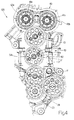
- numeral 10 indicates as a whole a distribution unit related to a single-cylinder endothermic engine 100 (figure 2) particularly suitable for motorcycle applications, such as motocross, enduro or supermotard.
- engine 100 (figure 2) further comprises a cylinder 20, in which a combustion chamber 21 (with central axis (a) of symmetry) is defined, within which combustion chamber there is a piston 20a to which a connecting rod 20b is hinged.
- a crank 22 belonging to a crankshaft 23 is associated to connecting rod 20b by means of a hinge (not shown).
- Engine 100 further comprises a head 30 resting on a horizontal upper surface SS of cylinder 20.
- the seats adapted to accommodate the two fuel/air mixture suction valves, the two burnt gas exhaust valves and a central accommodation spark plug seat, are obtained in head 30.
- valve actuating assembly 40 provided with two camshafts 41a, 41b and corresponding tappets (not shown) is located on top of head 30 (figure 4) .
- timing assembly 10 indeed, mechanically connects camshaft 23 with camshafts 41a, 41b for actuating the valves of head 30 according to a predetermined cycle (figure 4).
- timing assembly 10 extends laterally to cylinder 20 and to head 30, and is of the "rigid" type, not contemplating the use of belts or pulleys, but only of toothed wheels.
- timing assembly 10 comprises three straight toothed wheels 11, 12, 13 which form a gear set adapted to transfer the motion of crankshaft 23 to camshafts 41a, 41b, starting from a toothed pinion 24 (keyed onto crankshaft 23) for reaching toothed wheels 42a, 42b keyed onto corresponding camshafts 41a, 41b (figure 4).
- the innovative part resides essentially in a supporting system 50 of a generic toothed wheel 12 of a casing CT of engine 100 and external wall PT of cylinder 20 (figures 1, 2, 3).
- a through hole 51 in made in casing CT and a blank hole 52 is made in wall PT of cylinder 20.
- Holes 50 and 51 are aligned along a longitudinal axis of symmetry (c) (and of rotation of toothed wheel 12), which is perpendicular to the aforesaid axis (a) of combustion chamber 21.
- supporting system 50 belongs to a first bushing 53, presenting a shank 53a and a head 53b.
- First bushing 53 is supported by wall PT.
- Head 53b of first bushing 53 is located in a gap INT provided between casing CT and wall PT of cylinder 20.
- first bushing 53 Furthermore, a threaded through hole 53c and an aperture 53d are provided in first bushing 53 for the purposes which will be specified in greater detail below.
- a second bushing 54 which also comprises a shank 54a and a head 54b, also belongs to system 50.
- first bushing 53 and second bushing 54 have the same central axis of symmetry (c). Like first bushing 53, also second bushing 54 contemplates a central through hole 54d (not threaded) and an aperture 54e.
- toothed wheel 12 is accommodated in gap INT in use.
- head 54b ends with a flange 54c (figure 4), which, in use, rests on the external surface of casing CT.
- a screw 55 is used to secure second bushing 54 on first bushing 53.
- through holes 53c, 54d and screw 55 present a central axis of symmetry (d) which does not coincide with the aforesaid axis (c). Indeed, as shown in figure 1, axis (d) presents an eccentricity (E) with respect to axis (c).
- eccentricity (E) was provided to prevent undesired rotations of bushing 54 with respect to bushing 53 during the fastening of screw 55 in threaded hole 53c of bushing 53 itself.
- a seat 56 which contains a portion of a hub MZ of toothed wheel 12 and a roller bearing 57, is created between an upper surface 53e of head 53b of first bushing 53 and a lower surface 54f of head 54b of second bushing 54.
- Bearing 57 is used to support hub MZ and thus toothed wheel 12.
- hub MZ is provided in a known manner with a through hole MZ* in which bearing 57 is accommodated.
- head 30 is not yet mounted on cylinder 20.
- the assembler In use, the assembler firstly inserts shank 53a of first bushing 53 into blank hole 52 made on external wall PT of cylinder 20.
- the assembler starts to insert shank 54a in through hole 51 so that the end of such shank 54a is inserted in aperture 53d made in head 53b of first bushing 53.
- screw 55 can be inserted in through hole 54d and this screw 55 is indeed fastened in the treading provided on hole 53c.
- second bushing 54 is "packed” on first bushing 53, further “sandwiching” bearing 57 and hub MZ together.
- At least one screw 58a (or two) is provided, which is crossed through a hole 58b made on flange 54c and is fastened in a threaded hole 58c on a casing CT (figures 1, 4).
- screw 58a has the further function of preventing the random loosening of screw 55 due to the vibrations which are developed during the operation of engine 100.
- the main advantages of the supporting system object of the present invention are the maximum assembly simplicity and the capability of adapting to minor movements (in the order of a few hundredths of a millimeter) of the toothed wheel and/or the bearing axis along a direction identified by axis (c).
Landscapes
- Engineering & Computer Science (AREA)
- Mechanical Engineering (AREA)
- General Engineering & Computer Science (AREA)
- Chemical & Material Sciences (AREA)
- Combustion & Propulsion (AREA)
- Gears, Cams (AREA)
- Devices For Conveying Motion By Means Of Endless Flexible Members (AREA)
Applications Claiming Priority (1)
| Application Number | Priority Date | Filing Date | Title |
|---|---|---|---|
| IT000472A ITBO20060472A1 (it) | 2006-06-16 | 2006-06-16 | Sistema di supporto di una ruota dentata su un carter di un motore a combustiomne interna |
Publications (2)
| Publication Number | Publication Date |
|---|---|
| EP1867861A2 true EP1867861A2 (de) | 2007-12-19 |
| EP1867861A3 EP1867861A3 (de) | 2009-09-23 |
Family
ID=38565158
Family Applications (1)
| Application Number | Title | Priority Date | Filing Date |
|---|---|---|---|
| EP07110426A Withdrawn EP1867861A3 (de) | 2006-06-16 | 2007-06-15 | Stützsystem eines Zahnrades auf einem Gehäuse eines Verbrennungsmotors |
Country Status (2)
| Country | Link |
|---|---|
| EP (1) | EP1867861A3 (de) |
| IT (1) | ITBO20060472A1 (de) |
Cited By (3)
| Publication number | Priority date | Publication date | Assignee | Title |
|---|---|---|---|---|
| EP2664751A1 (de) * | 2012-05-15 | 2013-11-20 | MAN Truck & Bus AG | Steuertrieb für eine ventilgesteuerte Brennkraftmaschine |
| JP2014080883A (ja) * | 2012-10-15 | 2014-05-08 | Isuzu Motors Ltd | ギアシャフト支持構造 |
| EP3438434A4 (de) * | 2016-03-29 | 2019-02-06 | Yanmar Co., Ltd. | Motorvorrichtung |
Family Cites Families (4)
| Publication number | Priority date | Publication date | Assignee | Title |
|---|---|---|---|---|
| FR780109A (fr) * | 1933-10-31 | 1935-04-19 | Bristol Aeroplane Co Ltd | Perfectionnements aux mécanismes de commande des soupapes dans les moteurs à combustion interne à cylindres multiples |
| US4573439A (en) * | 1979-12-18 | 1986-03-04 | Cummins Engine Company, Inc. | Oil pump arrangement for supplying oil under pressure in an internal combustion engine |
| DE10124856A1 (de) * | 2001-05-22 | 2002-11-28 | Bayerische Motoren Werke Ag | Antrieb für einen Ventiltrieb einer Brennkraftmaschine |
| DE10306392A1 (de) * | 2003-02-15 | 2004-08-26 | Volkswagen Ag | Stirnrad-Nockenwellenantrieb für eine Brennkraftmaschine |
-
2006
- 2006-06-16 IT IT000472A patent/ITBO20060472A1/it unknown
-
2007
- 2007-06-15 EP EP07110426A patent/EP1867861A3/de not_active Withdrawn
Cited By (5)
| Publication number | Priority date | Publication date | Assignee | Title |
|---|---|---|---|---|
| EP2664751A1 (de) * | 2012-05-15 | 2013-11-20 | MAN Truck & Bus AG | Steuertrieb für eine ventilgesteuerte Brennkraftmaschine |
| CN103422927A (zh) * | 2012-05-15 | 2013-12-04 | 曼卡车和巴士股份公司 | 用于气门控制式内燃发动机的正时传动件 |
| RU2622358C2 (ru) * | 2012-05-15 | 2017-06-14 | Ман Трак Унд Бас Аг | Механизм клапанного газораспределения для управляемого с помощью клапанов двигателя внутреннего сгорания |
| JP2014080883A (ja) * | 2012-10-15 | 2014-05-08 | Isuzu Motors Ltd | ギアシャフト支持構造 |
| EP3438434A4 (de) * | 2016-03-29 | 2019-02-06 | Yanmar Co., Ltd. | Motorvorrichtung |
Also Published As
| Publication number | Publication date |
|---|---|
| ITBO20060472A1 (it) | 2007-12-17 |
| EP1867861A3 (de) | 2009-09-23 |
Similar Documents
| Publication | Publication Date | Title |
|---|---|---|
| CN111373124B (zh) | 发动机的可变气门正时系统 | |
| JP4975357B2 (ja) | カム軸により回転駆動される補機を備える内燃機関 | |
| CN101512109A (zh) | 组合式凸轮轴和设置有该组合式凸轮轴的内燃机 | |
| EP2057369B1 (de) | Zylinderkopf | |
| EP1867861A2 (de) | Stützsystem eines Zahnrades auf einem Gehäuse eines Verbrennungsmotors | |
| JPS60243306A (ja) | 内燃機関のシリンダヘツド組立体構造 | |
| JP2004278765A (ja) | ボルトおよび内燃機関 | |
| US6953015B2 (en) | Engine | |
| JP2008157107A (ja) | 気化器の取り付け構造 | |
| JP6069172B2 (ja) | 内燃機関のホルダ構造 | |
| JP6711147B2 (ja) | エンジンのチェーンカバー構造 | |
| TWI248491B (en) | Rotation prevention device for rocker arm shaft | |
| US10215061B2 (en) | Internal combustion engine | |
| JP2008157106A (ja) | V型エンジン | |
| JP4792423B2 (ja) | 空冷式v型エンジン | |
| JP3294963B2 (ja) | 熱機関のシリンダヘッドにおけるロッカシャフト用組立ユニット | |
| JP2003083009A (ja) | 内燃機関の動弁装置におけるロッカアームシャフトの回り止め装置 | |
| JP5226585B2 (ja) | カムギアトレーン式エンジン | |
| JP2013096389A (ja) | モノブロックエンジン | |
| JP6686417B2 (ja) | エンジン | |
| JPH08254167A (ja) | インジェクタの取付構造 | |
| JP6686416B2 (ja) | エンジン | |
| JP2006077705A (ja) | 内燃機関のシリンダヘッド組立体 | |
| JP2012087762A (ja) | 内燃機関の可変動弁装置 | |
| JP2004183587A (ja) | 直噴インジェクタの取付構造 |
Legal Events
| Date | Code | Title | Description |
|---|---|---|---|
| PUAI | Public reference made under article 153(3) epc to a published international application that has entered the european phase |
Free format text: ORIGINAL CODE: 0009012 |
|
| AK | Designated contracting states |
Kind code of ref document: A2 Designated state(s): AT BE BG CH CY CZ DE DK EE ES FI FR GB GR HU IE IS IT LI LT LU LV MC MT NL PL PT RO SE SI SK TR |
|
| AX | Request for extension of the european patent |
Extension state: AL BA HR MK YU |
|
| PUAL | Search report despatched |
Free format text: ORIGINAL CODE: 0009013 |
|
| AK | Designated contracting states |
Kind code of ref document: A3 Designated state(s): AT BE BG CH CY CZ DE DK EE ES FI FR GB GR HU IE IS IT LI LT LU LV MC MT NL PL PT RO SE SI SK TR |
|
| AX | Request for extension of the european patent |
Extension state: AL BA HR MK RS |
|
| AKX | Designation fees paid | ||
| REG | Reference to a national code |
Ref country code: DE Ref legal event code: 8566 |
|
| STAA | Information on the status of an ep patent application or granted ep patent |
Free format text: STATUS: THE APPLICATION IS DEEMED TO BE WITHDRAWN |
|
| 18D | Application deemed to be withdrawn |
Effective date: 20100324 |