EP1868286A2 - Doppelquellenstromerzeugungssystem - Google Patents
Doppelquellenstromerzeugungssystem Download PDFInfo
- Publication number
- EP1868286A2 EP1868286A2 EP07252030A EP07252030A EP1868286A2 EP 1868286 A2 EP1868286 A2 EP 1868286A2 EP 07252030 A EP07252030 A EP 07252030A EP 07252030 A EP07252030 A EP 07252030A EP 1868286 A2 EP1868286 A2 EP 1868286A2
- Authority
- EP
- European Patent Office
- Prior art keywords
- voltage
- power
- current
- magnitude
- low
- Prior art date
- Legal status (The legal status is an assumption and is not a legal conclusion. Google has not performed a legal analysis and makes no representation as to the accuracy of the status listed.)
- Withdrawn
Links
Images
Classifications
-
- H—ELECTRICITY
- H02—GENERATION; CONVERSION OR DISTRIBUTION OF ELECTRIC POWER
- H02J—ELECTRIC POWER NETWORKS; CIRCUIT ARRANGEMENTS OR SYSTEMS FOR SUPPLYING OR DISTRIBUTING ELECTRIC POWER; SYSTEMS FOR STORING ELECTRIC ENERGY
- H02J7/00—Circuit arrangements for charging or discharging batteries or for supplying loads from batteries
- H02J7/14—Circuit arrangements for charging or discharging batteries or for supplying loads from batteries for charging batteries from dynamo-electric generators driven at varying speed, e.g. on vehicle
- H02J7/1438—Circuit arrangements for charging or discharging batteries or for supplying loads from batteries for charging batteries from dynamo-electric generators driven at varying speed, e.g. on vehicle in combination with power supplies for loads other than batteries
-
- H—ELECTRICITY
- H02—GENERATION; CONVERSION OR DISTRIBUTION OF ELECTRIC POWER
- H02M—APPARATUS FOR CONVERSION BETWEEN AC AND AC, BETWEEN AC AND DC, OR BETWEEN DC AND DC, AND FOR USE WITH MAINS OR SIMILAR POWER SUPPLY SYSTEMS; CONVERSION OF DC OR AC INPUT POWER INTO SURGE OUTPUT POWER; CONTROL OR REGULATION THEREOF
- H02M3/00—Conversion of DC power input into DC power output
- H02M3/02—Conversion of DC power input into DC power output without intermediate conversion into AC
- H02M3/04—Conversion of DC power input into DC power output without intermediate conversion into AC by static converters
- H02M3/10—Conversion of DC power input into DC power output without intermediate conversion into AC by static converters using discharge tubes with control electrode or semiconductor devices with control electrode
- H02M3/145—Conversion of DC power input into DC power output without intermediate conversion into AC by static converters using discharge tubes with control electrode or semiconductor devices with control electrode using devices of a triode or transistor type requiring continuous application of a control signal
- H02M3/155—Conversion of DC power input into DC power output without intermediate conversion into AC by static converters using discharge tubes with control electrode or semiconductor devices with control electrode using devices of a triode or transistor type requiring continuous application of a control signal using semiconductor devices only
- H02M3/156—Conversion of DC power input into DC power output without intermediate conversion into AC by static converters using discharge tubes with control electrode or semiconductor devices with control electrode using devices of a triode or transistor type requiring continuous application of a control signal using semiconductor devices only with automatic control of output voltage or current, e.g. switching regulators
- H02M3/158—Conversion of DC power input into DC power output without intermediate conversion into AC by static converters using discharge tubes with control electrode or semiconductor devices with control electrode using devices of a triode or transistor type requiring continuous application of a control signal using semiconductor devices only with automatic control of output voltage or current, e.g. switching regulators including plural semiconductor devices as final control devices for a single load
- H02M3/1582—Buck-boost converters
-
- H—ELECTRICITY
- H02—GENERATION; CONVERSION OR DISTRIBUTION OF ELECTRIC POWER
- H02P—CONTROL OR REGULATION OF ELECTRIC MOTORS, ELECTRIC GENERATORS OR DYNAMO-ELECTRIC CONVERTERS; CONTROLLING TRANSFORMERS, REACTORS OR CHOKE COILS
- H02P9/00—Arrangements for controlling electric generators for the purpose of obtaining a desired output
- H02P9/14—Arrangements for controlling electric generators for the purpose of obtaining a desired output by variation of field
- H02P9/26—Arrangements for controlling electric generators for the purpose of obtaining a desired output by variation of field using discharge tubes or semiconductor devices
- H02P9/30—Arrangements for controlling electric generators for the purpose of obtaining a desired output by variation of field using discharge tubes or semiconductor devices using semiconductor devices
- H02P9/305—Arrangements for controlling electric generators for the purpose of obtaining a desired output by variation of field using discharge tubes or semiconductor devices using semiconductor devices controlling voltage
- H02P9/307—Arrangements for controlling electric generators for the purpose of obtaining a desired output by variation of field using discharge tubes or semiconductor devices using semiconductor devices controlling voltage more than one voltage output
Definitions
- the present invention relates to power generation systems, and more particularly to a power generation system for meeting a variety of voltage requirements.
- Generators are used to convert mechanical energy into electrical energy. Depending on the application, a specific type of generator may be employed to generate a desired output signal.
- a generator found on an automobile (commonly referred to as an alternator) converts mechanical energy provided by the vehicles combustion engine to provide electrical power to on-board electronics, as well as to charge the vehicle's battery.
- on-board electronics and the vehicle's battery are designed to require the same voltage (e.g., 12 volts (V)), which allows a single generator to provide the necessary electrical power.
- the voltage requirement of one load may differ from the voltage requirement of another load.
- a vehicle designed to provide refrigerated transportation requires high voltage alternating current (AC) power (e.g., 120 VAC) to operate the refrigeration system, and relatively low voltage (e.g., 12 VDC) to power on-board electronics and to charge the battery.
- AC alternating current
- relatively low voltage e.g. 12 VDC
- the generator could accurately maintain the DC voltage provided to the DC load at a desired level, providing a high-quality DC voltage.
- the present invention provides a dual source power generating system that includes a rotating magnetic field and a stator structure having a first winding and a second winding.
- the rotating magnetic field generates a high-voltage AC power in the first winding, and a low-voltage AC power in the second winding.
- a rectifier and DC-DC converter coupled to the second winding operates to convert the low-voltage AC power to a low-voltage DC power.
- a controller connected to monitor the voltage and current of the low-voltage DC power provided to a DC load calculates pulse width modulation (PWM) signals and provides the PWM signals to the DC-DC converter to maintain the low-voltage DC power at a desired level.
- PWM pulse width modulation
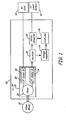
- FIG. 1 is a functional block diagram of a dual source power generating system connected to receive mechanical energy from a prime mover and to provide dual source power.
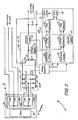
- FIG. 2 is a hybrid circuit/functional diagram of the dual source power generating system shown in FIG. 1.
- the power generating system of the present invention provides multiple output voltages using a single generator, including a high quality DC output.
- the generator includes a stator that is wound with a first winding and a second winding, wherein the first winding interacts with the magnetic flux generated by a rotor to generate a first AC output voltage and the second winding interacts with the magnetic flux generated by the rotor to generate a second AC output voltage.
- the magnitude of the AC output voltage generated by the first and second windings is dependent in part on the number of turns included in each winding.
- the power generating system includes a rectifier, a DC-DC converter and controller to convert the second AC output voltage to a desired DC output voltage.
- the present invention therefore provides a single generator that is capable of providing at least two types of output voltages that differ in magnitude, wherein at least one of the output voltages is a high quality DC voltage.
- One application of this system is for a vehicle having a refrigeration system that requires high voltage AC power (i.e., roughly 120 V AC, 60 Hz power).
- the generator of the present invention could be used in a number of similar applications that otherwise would require the use of at least two separate generators.
- FIG. 1 is a functional block diagram of power-generating system 10 connected to receive mechanical power from prime mover 12 and to deliver AC power to AC load 14 and high quality DC power to DC load/battery 16.
- Power generating system 10 includes AC generator 18, rectifier 20, DC-DC converter 22, voltage regulator 24 and controller 26.
- AC generator 18 includes rotor 28 and stator 30, wherein first stator windings 32 and second stator windings 34 are wound around stator 30. As shown in FIG. 2, first stator windings 32 and second stator windings 34 may each include three individual windings for generating three-phase AC power.
- generator 18 is a wound field synchronous machine, wherein field windings wrapped around rotor 28 are excited such that a magnetic field is generated by rotor 28.
- generator 18 is a permanent magnet machine in which no external excitation is required to generate the magnetic field. Mechanical energy received from prime mover 12 causes rotor 28 to turn, resulting in a rotating magnetic field being presented to stator 30. The rotating magnetic field generates a corresponding AC voltage in first stator winding 32 and second stator winding 34.
- first stator windings 32 and second stator windings 34 are based on the strength of the,magnetic field generated by rotor 28, the speed of rotor 28, and the number of turns making up first stator windings 32 and second stator windings 34.
- first stator winding 32 includes a large number of turns resulting in a relatively large AC voltage (e.g., 115 volts) being provided to AC load 14.
- DC load/battery 16 requires relatively low voltage DC power (e.g., 12 volts). Therefore, second stator windings 34 have a relatively low number of turns, resulting in relatively low voltage AC power (e.g., 20 volts) being provided by generator 18.
- the low voltage power generated by second stator windings 34 is first converted to low voltage DC power by rectifier 20.
- the rectified DC voltage is provided to both voltage regulator 24 and DC-DC converter 22.
- Voltage regulator 24 acts as a power supply, providing controller 26 with the necessary DC power to operate.
- Controller 26 monitors the DC output provided by DC-DC converter 22 to DC load 16 and provides input to DC-DC converter 22 based on the monitored DC output such that a desired DC output is provided to DC load 16. That is, DC-DC converter 22 provides a controlled DC output to DC load 16 based on input received from controller 26.
- generator 18 provides high voltage AC power to AC load 14 and a high quality-low voltage power to DC load 16 without the need for a second generator.
- DC-DC converter provides DC power that is controlled to a desired magnitude, resulting in high quality DC voltage being provided to DC load 16.
- FIG. 2 is a circuit diagram illustrating circuit components employed by power generation system 10.
- Generator 18 includes rotor 28 and stator 30, wherein stator 30 includes first stator windings 32 and second stator windings 34.
- first stator windings 32 include three individual windings 38, 40 and 42 for generating three phase AC power denoted Va, Vb, and Vc, respectively.
- second stator windings 34 include three individual windings 44, 46 and 48 for generating three phase AC denoted Vx, Vy and Vz.
- the number of turns included in individual windings 38, 40 and 42 is selected to generate approximately 120 volts AC line-to-neutral three-phase power at 60 Hz at outputs Va, Vb, and Vc.
- the number of turns included in windings 44, 46 and 48 is selected to generate approximately 20 volts AC line-to-neutral three-phase power at 60 Hz at outputs Vx, Vy, and Vz. Therefore, the number of turns included in windings 38, 40 and 42 is greater than the number of turns included in windings 44, 46 and 48.
- the AC output voltages generated by the first and second set of windings can be varied to meet the requirements of the application by varying the number of turns included in the respective windings.
- the AC output voltage generated by first set of windings 32 provides high voltage AC power to a respective load (not shown) via output voltages Va, Vb, and Vc.
- the AC output voltage generated by second stator windings. 34 provides low voltage AC power to rectifier 20, which includes diodes D1, D2, D3, D4, D5, and D6 connected in a bridge configuration that converts the low voltage AC power to a low voltage DC power.
- Capacitors C1 and C2 are connected in series across rectifier 20 and together act to reduce ripple in the low voltage DC power provided to DC-DC converter 22.
- Voltage regulator 24 is connected between capacitors C1 and C2, and provides the DC voltage necessary to operate controller 26.
- DC-DC converter 22 converts the low voltage DC power provided by rectifier 20 to a controlled, high quality, low voltage DC power that is provided to DC output/battery 16.
- DC-DC converter 22 includes transistor 50, inductor 52, diode D7, voltage sensor 54, and current sensor 56.
- DC-DC converter 22 is connected in a buck or step-down configuration to convert low voltage DC power received from rectifier 20 to a reduced voltage DC output that is provided to DC load/battery 16.
- DC-DC converter 22 may be connected to step-up voltage provided by rectifier 20. Control of the low voltage DC power provided by DC-DC converter 22 is done by selectively turning transistor 50 ON and OFF such that low voltage DC power provided by rectifier 20 is selectively applied to inductor 52.
- voltage sensor 54 and current sensor 56 provide feedback to controller 26 with respect to present output voltage and output current being provided to DC load 16. Based on the measurements received from voltage sensor 54 and current sensor 56, controller 26 controls the state of transistor 50 to maintain the desired DC output voltage.
- Controller 26 includes voltage reference 58, voltage comparator 60, carrier signal 64, first PWM generator 62, AND gate 66, current reference 68, current comparator 70, second PWM generator 72, and gate drive 74.
- Voltage reference 58 represents the desired DC output voltage to be provided by DC-DC converter 22
- current reference 68 represents the desired DC output current to be provided by DC-DC converter 22.
- Calculation of the PWM signal to be applied to the gate of transistor 50 includes calculating separately the PWM signals related to maintaining a desired voltage level and the PWM signals related to maintaining a desired current level.
- the voltage related PWM signals and current related PWM signals are combined to generate the actual PWM signal provided to the gate of transistor 50.
- the combination of voltage and current calculations performed by controller 26 not only maintains the desired DC output voltage, but also protects DC load 16 from overcurrent conditions.
- reference voltage 58 is compared with voltage sensed by voltage sensor 54 at voltage comparator block 60.
- Voltage comparator block 60 compares the desired DC output voltage represented by reference voltage 58 with the actual DC output voltage sensed by voltage sensor 54.
- voltage comparator block 60 calculates the difference between the sensed DC output and reference voltage 58.
- voltage comparator block 60 employs proportional, integral (PI) control to calculate error between the sensed DC output and the reference voltage 58.
- the calculated difference or error between the sensed DC output voltage and the reference voltage 58 along with a carrier waveform 64 are provided to PWM generator 64.
- Carrier waveform 64 is a saw-tooth shaped triangular waveform.
- the PWM waveform is generated by comparing the error generated by voltage comparator block 60 with carrier waveform 64.
- the resulting PWM signal is designed to cause the DC output voltage to increase or decrease (as required) toward the desired output voltage.
- a similar process is carried out with respect to the current sensed by current sensor 56.
- Current reference value 68 is compared with the measured DC current (as sensed by current sensor 56) by current comparator block 70.
- a resulting error value calculated either as a difference between the two values or using PI control, is provided to PWM generator 72, which calculates a PWM waveform related to DC output current using carrier signal 64.
- the PWM waveform generated by PWM generator 62 (and relating to sensed DC output voltage) and the PWM waveform generated by PWM generator 72 (and relating to sensed DC output current) are provided to AND gate 66, which performs a logical AND operation on the respective PWM waveforms.
- the resulting combination of the PWM waveform generated by PWM generator 62 and the PWM waveform generated by PWM generator 72 is the PWM signal that is provided to DC-DC converter 22 by gate drive 74.
- the benefit of combining PWM waveforms generated with respect to both measured voltage and current values of the DC output voltage is the ability of DC-DC converter to provide a DC output having a desired voltage magnitude, while protecting DC-DC converter (as well as DC load 16) from overcurrent or short circuit conditions. That is, if the DC output voltage provided to DC load 16 drops below the desired DC voltage level, the resulting PWM waveform generated by controller 26 will increase the ON time of transistor 50, increasing the DC output voltage. Likewise, if the current being drawn by DC load 16 exceeds the desired DC output current (such as in a overcurrent or short circuit situation), the resulting PWM waveform related to DC output current will reduce the ON time of transistor 50, and therefore reduce the amount of current provided to DC load 16.
Landscapes
- Engineering & Computer Science (AREA)
- Power Engineering (AREA)
- Rectifiers (AREA)
- Control Of Eletrric Generators (AREA)
Applications Claiming Priority (1)
| Application Number | Priority Date | Filing Date | Title |
|---|---|---|---|
| US11/439,480 US7439715B2 (en) | 2006-05-22 | 2006-05-22 | Dual source power generating system |
Publications (2)
| Publication Number | Publication Date |
|---|---|
| EP1868286A2 true EP1868286A2 (de) | 2007-12-19 |
| EP1868286A3 EP1868286A3 (de) | 2009-12-16 |
Family
ID=38476832
Family Applications (1)
| Application Number | Title | Priority Date | Filing Date |
|---|---|---|---|
| EP07252030A Withdrawn EP1868286A3 (de) | 2006-05-22 | 2007-05-17 | Doppelquellenstromerzeugungssystem |
Country Status (2)
| Country | Link |
|---|---|
| US (1) | US7439715B2 (de) |
| EP (1) | EP1868286A3 (de) |
Cited By (2)
| Publication number | Priority date | Publication date | Assignee | Title |
|---|---|---|---|---|
| US8581466B2 (en) | 2010-08-27 | 2013-11-12 | Hamilton Sundstrand Corporation | Knurled multiple conductor windings |
| WO2015183353A1 (en) * | 2014-05-30 | 2015-12-03 | Abb Technology Ag | Electric power generation and distribution for islanded or weakly-connected systems |
Families Citing this family (19)
| Publication number | Priority date | Publication date | Assignee | Title |
|---|---|---|---|---|
| US20080111422A1 (en) * | 2006-10-02 | 2008-05-15 | Minks Floyd M | Voltage Regulator and Power System with a Voltage Boost for a Low Input Voltage |
| KR101010352B1 (ko) * | 2008-05-30 | 2011-01-25 | 삼성중공업 주식회사 | 전력 제어 장치 및 방법 |
| US8203317B2 (en) * | 2009-03-24 | 2012-06-19 | Infineon Technologies Ag | Control parameter adaptation dependent on rotational speed |
| US8050004B2 (en) * | 2009-04-19 | 2011-11-01 | Hamilton Sundstrand Corporation | Power circuit with feed through protection circuit |
| US8269393B2 (en) * | 2009-06-18 | 2012-09-18 | Hamilton Sundstrand Corporation | Crowned end winding support for main wound field of a generator |
| US8299738B2 (en) * | 2009-11-20 | 2012-10-30 | Hamilton Sundstrand Corporation | Multi-tasking power processor for a vehicle electric system |
| US8358111B2 (en) * | 2009-12-03 | 2013-01-22 | Hamilton Sundstrand Corporation | Architecture for dual source electric power generating system |
| US8310211B1 (en) * | 2009-12-17 | 2012-11-13 | Advanced Power Systems, LLC | Auto-regulated motion power system |
| US8378641B2 (en) * | 2010-07-12 | 2013-02-19 | Hamilton Sundstrand Corporation | Electric power generating system with boost converter/synchronous active filter |
| US8536730B2 (en) * | 2010-07-12 | 2013-09-17 | Hamilton Sundstrand Corporation | Electric power generating and distribution system comprising a decoupling filter and a solid state power controller |
| US8487498B2 (en) | 2010-07-30 | 2013-07-16 | Hamilton Sundstrand Corporation | Multiple conductor winding in stator |
| US20120194030A1 (en) * | 2011-01-31 | 2012-08-02 | Kollmorgen Corporation | Force Balanced Multivoltage Winding Configuration |
| US9537307B2 (en) * | 2011-07-19 | 2017-01-03 | Hamilton Sundstrand Corporation | Overvoltage protection method and device |
| DE102012207809A1 (de) * | 2012-05-10 | 2013-11-14 | Robert Bosch Gmbh | Reichweitenverlängerer, Antrieb und Kraftfahrzeug |
| US9819192B2 (en) | 2014-07-29 | 2017-11-14 | General Electric Company | Solid oxide fuel cell-based power generation and delivery system and method of operating the same |
| US10870465B2 (en) * | 2015-05-22 | 2020-12-22 | Polaris Industries Inc. | Power boost regulator |
| CA2986482C (en) | 2015-05-22 | 2021-07-06 | Polaris Industries Inc. | Power boost regulator |
| AU2019335065B2 (en) | 2018-09-03 | 2024-07-18 | Milspec Technologies Pty Ltd | A DC to DC converter for a vehicle alternator |
| US12009772B2 (en) * | 2021-12-07 | 2024-06-11 | Hamilton Sundstrand Corporation | Parallel excitation of motor start function for three stage synchronous generator |
Family Cites Families (24)
| Publication number | Priority date | Publication date | Assignee | Title |
|---|---|---|---|---|
| US3793544A (en) * | 1972-02-10 | 1974-02-19 | Caterpillar Tractor Co | Multiple winding, multiple voltage, alternator system |
| JPS5223308U (de) * | 1975-08-09 | 1977-02-18 | ||
| JP2699187B2 (ja) * | 1988-12-28 | 1998-01-19 | 株式会社アイ・ライティング・システム | 放電灯点灯装置 |
| US5169287A (en) * | 1991-05-20 | 1992-12-08 | General Electric Company | Shroud cooling assembly for gas turbine engine |
| JPH04368220A (ja) * | 1991-06-17 | 1992-12-21 | Matsushita Electric Ind Co Ltd | 自動車用空調装置 |
| US5448154A (en) * | 1992-07-03 | 1995-09-05 | Hitachi, Ltd. | Control device for battery charging AC generator used in motor vehicle |
| JPH07220887A (ja) * | 1994-01-28 | 1995-08-18 | Eye Lighting Syst Corp | 放電灯点灯装置 |
| US5929611A (en) * | 1994-09-14 | 1999-07-27 | Coleman Powermate, Inc. | Light weight rotor and stator with multiple coil windings in thermal contact |
| US5510696A (en) * | 1994-11-03 | 1996-04-23 | General Motors Corporation | Zero current switching between winding sets in a permanent magnet alternator having a split winding stator |
| US5977648A (en) * | 1996-10-21 | 1999-11-02 | Sundstrand Corporation | Hydraulically driven low reactance, large air gap permanent magnet generator and voltage regulation system for use therewith |
| US6020713A (en) * | 1998-01-05 | 2000-02-01 | Capstone Turbine Corporation | Turbogenerator/motor pulse width modulated controller |
| US5986902A (en) * | 1998-06-16 | 1999-11-16 | Lucent Technologies Inc. | Integrated protection circuit, method of providing current-limiting and short-circuit protection and converter employing the same |
| EP1052758B1 (de) * | 1999-05-10 | 2004-10-13 | STMicroelectronics S.r.l. | In einem als Spannungsregler und Batterieladegerät arbeitenden Gleichspannungsschalterwandler verwendbarer Frequenzumsetzer und Verfahren zu dieser Frequenzumsetzung |
| US6275012B1 (en) * | 1999-12-16 | 2001-08-14 | C.E. Niehoff & Co. | Alternator with regulation of multiple voltage outputs |
| US6355987B1 (en) * | 2000-06-27 | 2002-03-12 | General Electric Company | Power converter and control for microturbine |
| JP2002027787A (ja) * | 2000-07-03 | 2002-01-25 | Keyence Corp | 電動機駆動装置 |
| US6455951B1 (en) * | 2000-08-16 | 2002-09-24 | Yazaki North America, Inc. | Auto charger for system including a high voltage supply and a low voltage supply |
| US20040231831A1 (en) * | 2001-05-31 | 2004-11-25 | Houck Glenn M. | Apparatus which eliminates the need for idling by trucks |
| US6853173B2 (en) * | 2002-01-25 | 2005-02-08 | Broadcom Corporation | Programmable dual mode hysteretic power output controller |
| JP3705490B2 (ja) * | 2002-02-14 | 2005-10-12 | 矢崎総業株式会社 | 負荷駆動装置 |
| JP2004282827A (ja) * | 2003-03-13 | 2004-10-07 | Honda Motor Co Ltd | 発電装置 |
| JP3973638B2 (ja) * | 2003-09-05 | 2007-09-12 | 三洋電機株式会社 | 電源ユニット及びこれを有する電源システム |
| JP2006345592A (ja) * | 2005-06-07 | 2006-12-21 | Fuji Seratekku Kk | 極低速で回転する高出力発電機 |
| US7288923B1 (en) * | 2006-04-21 | 2007-10-30 | Pratt & Whitney Canada Corp. | Voltage-limited electric machine |
-
2006
- 2006-05-22 US US11/439,480 patent/US7439715B2/en not_active Expired - Fee Related
-
2007
- 2007-05-17 EP EP07252030A patent/EP1868286A3/de not_active Withdrawn
Cited By (2)
| Publication number | Priority date | Publication date | Assignee | Title |
|---|---|---|---|---|
| US8581466B2 (en) | 2010-08-27 | 2013-11-12 | Hamilton Sundstrand Corporation | Knurled multiple conductor windings |
| WO2015183353A1 (en) * | 2014-05-30 | 2015-12-03 | Abb Technology Ag | Electric power generation and distribution for islanded or weakly-connected systems |
Also Published As
| Publication number | Publication date |
|---|---|
| EP1868286A3 (de) | 2009-12-16 |
| US7439715B2 (en) | 2008-10-21 |
| US20070268004A1 (en) | 2007-11-22 |
Similar Documents
| Publication | Publication Date | Title |
|---|---|---|
| EP1868286A2 (de) | Doppelquellenstromerzeugungssystem | |
| US12301071B2 (en) | Motor control device, mechatronic unit, power generation system, boost converter system, and electric vehicle system | |
| US8427116B2 (en) | Starting/generating system with multi-functional circuit breaker | |
| JP5340379B2 (ja) | 電気自動車用の急速充電装置 | |
| US9515484B2 (en) | System and method for reducing reactive current on a common DC bus with multiple inverters | |
| KR101172340B1 (ko) | 영구 자석 교류기용 제어기 | |
| US8750008B2 (en) | Multi-phase converter for DC power supply with two choppers having magnetically coupled reactors | |
| US9325274B2 (en) | Apparatus for carrying out improved control of rotary machine | |
| KR950035037A (ko) | 유도부하에 대한 제어회로 | |
| KR20050003732A (ko) | 유도 전동기용 벡터 제어형 듀얼 인버터 시스템 | |
| US10976762B2 (en) | Control of an electrical power system responsive to sensing a ground fault | |
| US8305786B2 (en) | Power controller for electric vehicle | |
| KR101247282B1 (ko) | 직렬형 하이브리드 동력장치의 제어장치 | |
| US8339074B2 (en) | Power converter control apparatus | |
| US20090033302A1 (en) | Voltage conversion device | |
| CN100431257C (zh) | 永磁激励的同步电机的减少传感器的调节方法和装置 | |
| US20140103650A1 (en) | Dual-dc bus starter/generator | |
| JP2011234485A (ja) | インバータ式発動発電機 | |
| JP2015116092A (ja) | 電動車両 | |
| US7786708B2 (en) | Starter/generator system with control to address a voltage rise | |
| EP2624441A2 (de) | Integriertes Hochspannungsgleichstromerzeugungssystem | |
| US20080084639A1 (en) | Method and system for improving voltage regulator accuracy in vehicle alternators | |
| US20160023572A1 (en) | Activation Method for an Electric Machine | |
| CN102598467A (zh) | 用于在机动车的起动阶段期间使机动车发电机从电池中的电流消耗得以最小化的装置 | |
| KR101813060B1 (ko) | 스위칭 모드 파워 서플라이 |
Legal Events
| Date | Code | Title | Description |
|---|---|---|---|
| PUAI | Public reference made under article 153(3) epc to a published international application that has entered the european phase |
Free format text: ORIGINAL CODE: 0009012 |
|
| AK | Designated contracting states |
Kind code of ref document: A2 Designated state(s): AT BE BG CH CY CZ DE DK EE ES FI FR GB GR HU IE IS IT LI LT LU LV MC MT NL PL PT RO SE SI SK TR |
|
| AX | Request for extension of the european patent |
Extension state: AL BA HR MK YU |
|
| PUAL | Search report despatched |
Free format text: ORIGINAL CODE: 0009013 |
|
| AK | Designated contracting states |
Kind code of ref document: A3 Designated state(s): AT BE BG CH CY CZ DE DK EE ES FI FR GB GR HU IE IS IT LI LT LU LV MC MT NL PL PT RO SE SI SK TR |
|
| AX | Request for extension of the european patent |
Extension state: AL BA HR MK RS |
|
| RIC1 | Information provided on ipc code assigned before grant |
Ipc: H02M 3/158 20060101ALI20091110BHEP Ipc: H02M 7/155 20060101AFI20070919BHEP |
|
| 17P | Request for examination filed |
Effective date: 20100317 |
|
| 17Q | First examination report despatched |
Effective date: 20100415 |
|
| AKX | Designation fees paid |
Designated state(s): DE FR GB IT SE |
|
| STAA | Information on the status of an ep patent application or granted ep patent |
Free format text: STATUS: THE APPLICATION IS DEEMED TO BE WITHDRAWN |
|
| 18D | Application deemed to be withdrawn |
Effective date: 20100826 |