EP1870246A2 - Procédé destiné à l'impression d'une matière d'impression - Google Patents
Procédé destiné à l'impression d'une matière d'impression Download PDFInfo
- Publication number
- EP1870246A2 EP1870246A2 EP07012240A EP07012240A EP1870246A2 EP 1870246 A2 EP1870246 A2 EP 1870246A2 EP 07012240 A EP07012240 A EP 07012240A EP 07012240 A EP07012240 A EP 07012240A EP 1870246 A2 EP1870246 A2 EP 1870246A2
- Authority
- EP
- European Patent Office
- Prior art keywords
- printing
- inkjet
- output data
- current
- printed
- Prior art date
- Legal status (The legal status is an assumption and is not a legal conclusion. Google has not performed a legal analysis and makes no representation as to the accuracy of the status listed.)
- Granted
Links
- 238000007639 printing Methods 0.000 title claims abstract description 170
- 238000000034 method Methods 0.000 title claims abstract description 56
- 239000000758 substrate Substances 0.000 title claims abstract description 27
- 238000007641 inkjet printing Methods 0.000 claims abstract description 76
- 239000011159 matrix material Substances 0.000 claims abstract description 71
- 239000000463 material Substances 0.000 claims abstract description 17
- 238000007645 offset printing Methods 0.000 claims abstract description 6
- 230000005540 biological transmission Effects 0.000 claims abstract description 4
- 238000006243 chemical reaction Methods 0.000 claims description 18
- 230000009466 transformation Effects 0.000 claims description 9
- 230000001419 dependent effect Effects 0.000 claims description 2
- 238000005259 measurement Methods 0.000 claims description 2
- 238000005070 sampling Methods 0.000 claims 1
- 238000010008 shearing Methods 0.000 claims 1
- 239000000976 ink Substances 0.000 description 10
- 230000003287 optical effect Effects 0.000 description 9
- 230000000694 effects Effects 0.000 description 5
- 238000005352 clarification Methods 0.000 description 4
- 230000007423 decrease Effects 0.000 description 1
- 238000005516 engineering process Methods 0.000 description 1
- 230000008092 positive effect Effects 0.000 description 1
- 238000000844 transformation Methods 0.000 description 1
Images

Classifications
-
- B—PERFORMING OPERATIONS; TRANSPORTING
- B41—PRINTING; LINING MACHINES; TYPEWRITERS; STAMPS
- B41J—TYPEWRITERS; SELECTIVE PRINTING MECHANISMS, i.e. MECHANISMS PRINTING OTHERWISE THAN FROM A FORME; CORRECTION OF TYPOGRAPHICAL ERRORS
- B41J3/00—Typewriters or selective printing or marking mechanisms characterised by the purpose for which they are constructed
- B41J3/54—Typewriters or selective printing or marking mechanisms characterised by the purpose for which they are constructed with two or more sets of type or printing elements
- B41J3/546—Combination of different types, e.g. using a thermal transfer head and an inkjet print head
-
- B—PERFORMING OPERATIONS; TRANSPORTING
- B41—PRINTING; LINING MACHINES; TYPEWRITERS; STAMPS
- B41J—TYPEWRITERS; SELECTIVE PRINTING MECHANISMS, i.e. MECHANISMS PRINTING OTHERWISE THAN FROM A FORME; CORRECTION OF TYPOGRAPHICAL ERRORS
- B41J11/00—Devices or arrangements of selective printing mechanisms, e.g. ink-jet printers or thermal printers, for supporting or handling copy material in sheet or web form
- B41J11/008—Controlling printhead for accurately positioning print image on printing material, e.g. with the intention to control the width of margins
Definitions
- the invention relates to a method for printing a printing material according to the preamble of claim 1.
- inkjet printing devices In printing form-based, preferably operating on the offset printing principle printing machines, such. B. in web-fed rotary printing presses and sheetfed presses, find increasingly pressure-free inkjet printing devices use, in particular the customization of printed products produced by offset printing with z. As barcodes, numbering or other markings serve.
- Such inkjet printing devices have at least one inkjet print head, the so-called continuous inkjet principle, the drop-on-demand inkjet principle, the thermal inkjet principle, the bubble inkjet principle or any other inkjet Principle can be formed.
- the inkjet printheads usually have a nozzle row of several juxtaposed nozzles over which ink can be directed to a substrate to be printed.
- inkjet printing devices Since the maximum printing speed of inkjet printing devices is significantly lower than the maximum printing speed of offset printing devices, it is difficult to print inline on a substrate after offset printing and after inkjet printing.
- inkjet printing devices With a variety of inkjet printheads, namely on the one hand with multiple inkjet printheads transversely to the transport direction of the substrate or to the printing direction and on the other with a plurality of inkjet printheads in the transport direction of the printing material or in the printing direction, wherein the plurality of inkjet printheads are arranged in an array-like or matrix-like manner next to one another.
- the required number of inkjet printheads transversely to the printing direction is defined primarily by the desired printing resolution in relation to the given printing resolution of the inkjet printhead used and by the desired total printing width based on the given printing width of an inkjet printhead.
- the required number of inkjet printheads in the printing direction is determined primarily by two points, namely firstly that the desired printing speed is greater than the given printing speed of an inkjet printhead, and secondly that a plurality of printing inks via the inkjet printing device to be applied to a substrate.
- the achievable printing speed can also be increased by the or each inkjet printhead of an inkjet printing device to the transport direction the printing material and thus obliquely aligned or inclined to the printing direction.
- the inclination has the consequence that the effective distance of the nozzles transversely to the printing direction or transport direction of the printing material is reduced and thus the printing resolution can be increased transversely to the printing direction.
- the printing speed remains unchanged, it can then be printed with a higher areal coverage or optical density. Equally, however, the areal coverage or optical density can be kept constant while increasing the printing speed.
- this implementation takes place in the hardware of the inkjet printheads, but this has the disadvantage that this conversion is valid only for a defined inclination, only for a defined drop frequency and only for a defined printing speed. Changes z. As the printing speed, so it can not be reacted to, which ultimately results in the printing quality impairing distortions for the print image to be printed with the inkjet printing device.
- output data, in particular an output data matrix, of a print image to be printed by the inkjet printing device depends on a current print speed, depending on a current drop frequency of the or each inkjet print head of the inkjet printer and depending on a current skew angle of the or each nozzle row of or each inkjet printhead with respect to the transport direction of the printing material before transmission of the data to the inkjet printing device in target data, in particular a target data matrix, converted to the control of the inkjet printing device in real time.
- the conversion of the output data into the target data for controlling an inkjet printing device inclined in the printing direction be carried out independently of the hardware of the inkjet print heads of the inkjet printing device.
- the inventive conversion of the output data in the target data is thus carried out before the transfer of image information from the prepress to the inkjet printing device and thus between the prepress and the inkjet printing device.
- the conversion of the output data into the target data takes place in real time, wherein the current print speed, the current drop frequency and the current skew angle are variable variables in the conversion of the output data into the target data.
- the conversion of the output data in the target data z. B. be adapted to a changing printing speed, so that even with changing printing speeds with the inkjet printing device, a high print quality can be guaranteed.
- the conversion of the output data into the target data takes place via a transformation, such that an output data matrix is scaled and sheared in the printing direction as well as transversely to the printing direction.
- a scaling factor for scaling the output data matrix transversely printing direction is determined from the current skew angle, namely from the ratio of the expansion of the print image transversely to the printing direction with inclined inkjet printing device for extending the same transversely to the printing direction with non-inclined inkjet printing device.
- a scaling factor for scaling the output data matrix in the printing direction is determined from the current print speed and the current drop frequency.
- a shear angle to shear the output data matrix is determined from the current skew angle.
- the conversion of the output data into the target data takes place in such a way that an output data matrix is scanned step by step depending on the current skew angle, the current print speed and the current drop frequency, wherein if one or more nozzle positions of the inkjet Printer to hit a pixel in an output data matrix, a corresponding pixel is set in a target data matrix.
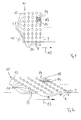
- FIG. 1 shows schematically an inkjet printhead comprising a nozzle row 10 of a plurality of juxtaposed nozzles 11, which are positioned along a row or line 12 at the same distance from each other.
- the spacing of the nozzles 11 of such a nozzle row 10 is predetermined by the technology used in the inkjet printing head.
- the printing material to be printed is preferably moved in the direction of the arrow 13 relative to the preferably stationary inkjet printing head, wherein in the case of a constant drop frequency of printing ink and a constant printing speed that shown in FIG Raster of possible positions 14 for drops of ink results.
- the droplet frequency, printing speed and the distance of the nozzles are selected such that four adjacent positions 14 of ink droplets describe a square 15 with a defined surface area.
- a distance X of the positions 14 in the printing direction determines the resolution in the printing direction
- a distance Y of the positions 14 transverse to the printing directions determines the resolution transverse to the printing direction, in Fig. 1, these two resolutions are equal.
- the resolution in the printing direction can be different in size than the resolution transverse to the printing direction. From the distance Y of the nozzles 11 transversely to the printing direction multiplied by the number of nozzles 11 results in the printable width or the extent of a printable with the inkjet print head print image transversely to the printing direction, wherein according to FIG. 1, the nozzle row 10 of nozzles 11 with the printing direction 13 includes an angle ⁇ of approximately 90 °.
- the surface area of the square 15 of FIG. 1 is a measure of the areal coverage or optical density with which printing can be carried out.
- Fig. 2 illustrates the pressure conditions, which then adjust when the nozzle row 10 is inclined from the nozzles 11 by an angle ⁇ to the printing direction 13, wherein in Fig. 2, the angle ⁇ , for example, 30 °. It follows immediately that the distance Y of the ink droplet positions 14 decreases transversely to the printing direction, whereby the resolution can be increased transversely to the printing direction. Should be printed in comparison to FIG. 1 with unchanged area coverage or unchanged optical density, the distance X between the positions for ink droplets can be increased in the printing direction by increasing the printing speed.
- the achievable area coverage or achievable optical density is visualized by a parallelogram 16 spanned by four adjacent positions 14, the area of the parallelogram 16 of FIG. 2 corresponding to the area of the square 15 of FIG.
- inkjet printheads or nozzle rows thereof are inclined relative to the transport direction of the printing material and thus the printing direction, there is a need to provide output data of a print image to be printed with the inkjet printing device in target data for controlling the inkjet printing device in a prepress stage to change.
- the conversion of the output data in the target data is done in real time, so that during printing z.
- B. changing printing speed the target data for controlling the inkjet printing device can be changed so as to always provide an optimal print image with the inkjet printing device under changing printing conditions.
- the current print speed, the current drop frequency and the current skew angle are therefore variable Sizes in the conversion of the output data of the prepress stage in the target data for controlling the inkjet printing device.
- the skew angle of the or each nozzle row of the or each inkjet printhead of the inkjet printing device is a variable size of the method of the invention, but the skew angle is ideally chosen so that at a given maximum printing speed and a given maximum printing speed maximum drop frequency just a geometric area coverage or optical density of 100% is given.
- the maximum printing speed is then only by physical parameters such. B. limits the drop speed itself and the associated placement accuracy of the ink droplets on the substrate.
- the skew angle can also be selected to provide areal coverage of less than 100%.
- the actual drop frequency is either the same or variable for all the nozzles of an inkjet printhead, and when a continuous inkjet printer is used, the drop frequency is the same for all nozzles, and then, if a drop-on-demand inkjet Pressure device is used, the drop frequency is variable.
- the current printing speed is detected by measurement via a sensor and represents a variable input variable for the conversion of the output data of the prepress for the inkjet printing device to be printed image in the target data for controlling the inkjet printing device.
- the output data is transformed into the target data via a transformation, namely such that output data in the printing direction and transversely to the output data are present in the form of an output data matrix, in particular an output bitmap print direction are scaled and further sheared to provide a target data matrix, in particular a target bitmap, for driving the inkjet printing device.
- a transformation namely such that output data in the printing direction and transversely to the output data are present in the form of an output data matrix, in particular an output bitmap print direction are scaled and further sheared to provide a target data matrix, in particular a target bitmap, for driving the inkjet printing device.
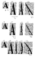
- reference numeral 17 is an output data matrix provided in a prepress stage for a print image to be printed by an inkjet printer, and this output data matrix 17 is an orthogonal output bitmap rastered using known techniques. In the simplest case, there are purely binary data per pixel, which means that one pixel of the output data matrix 17 is either set and thus black or unset and thus white.
- the printed image to be printed in the illustrated embodiment is an A, wherein in Fig. 3 an unencumbered and thus white pixel with the reference numeral 18 and a set and thus black pixel is designated by the reference numeral 19.
- the output data matrix 17 is first scaled transversely to the printing direction 13, whereby a scaling factor for the scaling transversely to the printing direction results from the current skew angle.
- the scaling factor for the scaling transversely to the printing direction results from a ratio of the printing width of the inclined inkjet printhead in relation to the printing width of the non-inclined inkjet printhead.
- the scaling factor for the scaling transversely to the printing direction results from the ratio of the extent of the printed image transversely to the printing direction with an inclined inkjet printing device for extending the printed image transversely to the printing direction with non-inclined inkjet printing device.
- a data matrix scaled by this scaling factor is designated by the reference numeral 20.
- FIG. 3 indicates a data matrix, which is scaled both transversely to the printing direction and in the printing direction, with the reference numeral 21.
- the output data matrix is sheared, a shear angle being determined from the current skew angle.
- a scaled by both scaling factors and transformed by the shear angle data matrix corresponding to the target data matrix for controlling the inkjet printing device is indicated in Fig. 3 by the reference numeral 22.
- Fig. 4 visualizes the effects on the transformation of the output data matrix when the printing speed is higher than in the embodiment of Fig. 3. Otherwise, in the embodiment of Fig. 4, all the parameters are unchanged from the embodiment of Fig. 3. Increasing the printing speed results in a different scaling in the printing direction, so that the data matrix 21 and thus ultimately also the target matrix 22 is changed compared to FIG. However, since only the printing speed has changed in comparison to FIG. 3, the scaling factor transversely to the printing direction and the shear angle remain unchanged.
- Fig. 5 visualizes the relationships in the transformation of the output data matrix 17 into a target data matrix 22 for the case in which the inkjet printing device relative to a curved guide element, such as. B. a cylinder, is tilted for printing material to be printed.
- a transformation is carried out to compensate for or compensate for differences in the transit time caused by the different distances of the nozzles of the or each inkjet printhead of the inkjet printing device to the printing substrate.
- this transformation is done to compensate for the different distances of the nozzles to the substrate between the scaling in the printing direction and the shear, but also here the order is arbitrary.
- a data matrix scaled in both directions and transformed to compensate for the different nozzle spacings is designated by the reference numeral 23, the target data matrix 22 additionally being sheared by the shear angle.
- the procedure is preferably such that the output data of the print image to be printed is adjusted so that such print image information associated with the nozzles at a greater distance from the substrate to be printed, compared with such print image information, the nozzles with a smaller distance are assigned by printing material to be printed, be moved to a position earlier in the printing direction.
- a second variant of the method according to the invention for converting the output data of the prepress stage into the target data for controlling the inkjet printing device is described below with reference to FIGS. 6 to 8, wherein this conversion of the output data into the target data according to the second variant of the present invention thereby in that an output data matrix is scanned step by step in dependence on the current skew angle, the current print speed and the current drop frequency, wherein if one or more nozzle positions of the inkjet printer device hit a pixel in the output data matrix, a corresponding pixel in the target data matrix is set.
- FIG. 6 shows, by way of example for an L to be printed with the aid of an inkjet printing device, an output data matrix 24 composed of 8 ⁇ 12 pixels, wherein pixels set for printing are shown in FIG. 6 as rounded squares 25.
- 200 dpi is assumed as the resolution for the output data matrix 24 in both directions, so that a screen width 26 of 127 ⁇ m results in both directions.
- this output data matrix 24 is virtually scanned. If one or more nozzle positions 11 strike a set pixel 25 in the output data matrix 24, a corresponding pixel 27 is set in the target data matrix.
- a step size 28 of this sample which corresponds to the raster width of the target data matrix, depends on the current print speed and the current drop frequency. The step size of the scan and thus the raster width of the target data matrix is greater, the greater the print speed.
- picture elements 27 set in the target data matrix are shown as circles, which are shown somewhat smaller than they could cover in terms of surface area, in order to ensure a clearer representation.
- the step size of the scanning or the raster width 28 of the target data matrix is increased by increasing the printing speed at a constant drop frequency, wherein in Fig. 8, the pixels 27 of the target data matrix have approximately the same dot density as the pixels 25 of the output data matrix. As a result, printing speed can be increased with almost unchanged optical density.
- the setting of the pixels in the target data matrix can be done in binary form or via gray scale modulation. Then, when the inkjet printing device uses binary inkjet printheads, pixels in the target data matrix, all of which have the same drop size, are set or not, depending on whether nozzle positions hit pixels in the output data matrix during the scan. If, on the other hand, an inkjet printing device is used whose inkjet printheads can modulate gray values, then when a nozzle position encounters a pixel in the output data matrix, the gray value in the target data matrix is set, which is the ratio of the areal coverage of an ink drop and the imaginary pixel area closest to this position.
- the target data matrix generated using the method described with reference to FIGS. 6 to 8 can be transformed to compensate for different distances of the nozzles from the print material to be printed, as described with reference to FIG. 5 become.
- the conversion of output data into target data described above is performed in real time, so that a speed change of the printing speed in the inkjet printing device can be taken into account.
- a side effect of the method described is that at a lower printing speed than the maximum printing speed, a higher optical density can be achieved. Especially when printing black and white graphics or when printing texts, this side effect has a positive effect on the print quality. However, if this side effect is perceived as disturbing, then the target data matrix can be thinned out by deleting pixels, in such a way that if only one pixel of the target data matrix has multiple pixels, only the best placed pixels are selected.
Landscapes
- Ink Jet (AREA)
- Particle Formation And Scattering Control In Inkjet Printers (AREA)
Applications Claiming Priority (1)
| Application Number | Priority Date | Filing Date | Title |
|---|---|---|---|
| DE102006029088A DE102006029088A1 (de) | 2006-06-24 | 2006-06-24 | Verfahren zum Bedrucken eines Bedruckstoffs |
Publications (3)
| Publication Number | Publication Date |
|---|---|
| EP1870246A2 true EP1870246A2 (fr) | 2007-12-26 |
| EP1870246A3 EP1870246A3 (fr) | 2008-07-16 |
| EP1870246B1 EP1870246B1 (fr) | 2010-01-06 |
Family
ID=38535370
Family Applications (1)
| Application Number | Title | Priority Date | Filing Date |
|---|---|---|---|
| EP07012240A Not-in-force EP1870246B1 (fr) | 2006-06-24 | 2007-06-22 | Procédé destiné à l'impression d'une matière d'impression |
Country Status (6)
| Country | Link |
|---|---|
| US (1) | US7571971B2 (fr) |
| EP (1) | EP1870246B1 (fr) |
| JP (1) | JP4885803B2 (fr) |
| CN (1) | CN101117061B (fr) |
| CA (1) | CA2592878C (fr) |
| DE (2) | DE102006029088A1 (fr) |
Families Citing this family (7)
| Publication number | Priority date | Publication date | Assignee | Title |
|---|---|---|---|---|
| US8201909B2 (en) * | 2008-12-03 | 2012-06-19 | Videojet Technologies Inc. | Inkjet printing system and method |
| JP5163669B2 (ja) * | 2010-02-26 | 2013-03-13 | 豊田合成株式会社 | 加飾印刷方法 |
| EP2420382B1 (fr) | 2010-08-20 | 2013-10-16 | Agfa Graphics N.V. | Système et procédé pour la création numérique d'un support d'impression utilisant une unité de tête d'impression multiple |
| JP5857205B2 (ja) * | 2012-09-10 | 2016-02-10 | パナソニックIpマネジメント株式会社 | ラインヘッド及びインクジェット装置 |
| US10321002B1 (en) * | 2018-02-14 | 2019-06-11 | Xerox Corporation | Variable data vector graphic pattern ink pantograph |
| KR102771553B1 (ko) * | 2019-07-15 | 2025-02-25 | 삼성디스플레이 주식회사 | 잉크젯 프린팅 장치 및 이를 이용한 잉크젯 프린팅 방법 |
| CN116021882B (zh) * | 2021-10-26 | 2025-09-16 | 深圳市汉森软件股份有限公司 | 喷头倾斜打印的参数计算方法、装置、设备及存储介质 |
Family Cites Families (20)
| Publication number | Priority date | Publication date | Assignee | Title |
|---|---|---|---|---|
| JPS60147348A (ja) * | 1984-01-11 | 1985-08-03 | Fuji Sangyo Kk | インクジエツトプリンタ |
| JPH02208049A (ja) * | 1989-02-08 | 1990-08-17 | Canon Inc | 液体噴射記録方法および装置 |
| JP3302785B2 (ja) * | 1993-06-08 | 2002-07-15 | 株式会社リコー | インクジェット記録装置 |
| DE4340164A1 (de) * | 1993-11-25 | 1995-06-01 | Roland Man Druckmasch | Verfahren zum Flüssigkeitsstrahldruck |
| JPH09201955A (ja) * | 1996-01-26 | 1997-08-05 | Seiko Epson Corp | 印刷装置 |
| DE19745136B4 (de) * | 1996-10-17 | 2007-07-12 | Heidelberger Druckmaschinen Ag | Rotationsbogendruckmaschine |
| JP2001232744A (ja) * | 2000-02-21 | 2001-08-28 | Fuji Photo Film Co Ltd | インクジェット記録方法を用いた平版印刷方法及び装置 |
| JP2001328254A (ja) * | 2000-05-19 | 2001-11-27 | Seiko Epson Corp | 記録方法及び記録装置 |
| DE10057061C1 (de) * | 2000-11-17 | 2002-05-23 | Koenig & Bauer Ag | Druckvorrichtung |
| JP2002361833A (ja) * | 2001-06-12 | 2002-12-18 | Fuji Photo Film Co Ltd | ハイブリッド印刷装置 |
| JP4704635B2 (ja) * | 2001-09-28 | 2011-06-15 | 株式会社セイコーアイ・インフォテック | インクジェットプリンタ |
| JP2003127368A (ja) * | 2001-10-29 | 2003-05-08 | Konica Corp | インクジェットプリント装置 |
| JP2003145777A (ja) * | 2001-11-16 | 2003-05-21 | Hitachi Printing Solutions Ltd | インクジェットプリンタ |
| US6533385B1 (en) * | 2001-12-14 | 2003-03-18 | Pitney Bowes Inc. | Method for determining a printer's signature and the number of dots per inch printed in a document to provide proof that the printer printed a particular document |
| JP4150250B2 (ja) * | 2002-12-02 | 2008-09-17 | 富士フイルム株式会社 | 描画ヘッド、描画装置及び描画方法 |
| JP3903073B2 (ja) * | 2004-03-31 | 2007-04-11 | 富士フイルム株式会社 | 滲み判定方法並びに画像記録方法及び装置 |
| JP2006076021A (ja) * | 2004-09-07 | 2006-03-23 | Tohoku Ricoh Co Ltd | 複合型画像形成装置 |
| JP2006076270A (ja) * | 2004-09-13 | 2006-03-23 | Tohoku Ricoh Co Ltd | 複合型画像形成装置 |
| JP4007357B2 (ja) * | 2004-09-29 | 2007-11-14 | 富士フイルム株式会社 | 画像形成装置及び方法 |
| US7448715B2 (en) * | 2004-10-08 | 2008-11-11 | Brother Kogyo Kabushiki Kaisha | Ink jet printer |
-
2006
- 2006-06-24 DE DE102006029088A patent/DE102006029088A1/de not_active Withdrawn
-
2007
- 2007-06-22 DE DE502007002529T patent/DE502007002529D1/de active Active
- 2007-06-22 JP JP2007165659A patent/JP4885803B2/ja not_active Expired - Fee Related
- 2007-06-22 CA CA2592878A patent/CA2592878C/fr not_active Expired - Fee Related
- 2007-06-22 EP EP07012240A patent/EP1870246B1/fr not_active Not-in-force
- 2007-06-22 US US11/767,310 patent/US7571971B2/en not_active Expired - Fee Related
- 2007-06-25 CN CN200710109562XA patent/CN101117061B/zh not_active Expired - Fee Related
Also Published As
| Publication number | Publication date |
|---|---|
| JP2008001105A (ja) | 2008-01-10 |
| DE502007002529D1 (de) | 2010-02-25 |
| US7571971B2 (en) | 2009-08-11 |
| JP4885803B2 (ja) | 2012-02-29 |
| CA2592878C (fr) | 2010-11-30 |
| DE102006029088A1 (de) | 2007-12-27 |
| CA2592878A1 (fr) | 2007-12-24 |
| CN101117061A (zh) | 2008-02-06 |
| US20080001982A1 (en) | 2008-01-03 |
| EP1870246B1 (fr) | 2010-01-06 |
| EP1870246A3 (fr) | 2008-07-16 |
| CN101117061B (zh) | 2011-04-20 |
Similar Documents
| Publication | Publication Date | Title |
|---|---|---|
| EP1870246B1 (fr) | Procédé destiné à l'impression d'une matière d'impression | |
| DE60025582T2 (de) | Drucker mit vereinfachtem Herstellungsverfahren und Herstellungsverfahren | |
| DE69221780T2 (de) | Tintenstrahlaufzeichnungsgerät | |
| DE69502605T2 (de) | Verfahren zum Betreiben eines Tintenstrahldruckers und Tintenstrahldrucker, dieses Verfahren benutzend | |
| DE60029291T2 (de) | Druckvorrichtung mit einer Funktion zur Korrektur der Fehlausrichtung von Punktpositionen | |
| DE69600415T2 (de) | Auflösungserhöhungs- und Verdünnungsverfahren zum Drucken von Rasterbildern | |
| EP1842668A2 (fr) | Dispositif supplémentaire pour une imprimante fonctionnant selon le principe d'impression offset | |
| EP0921008A1 (fr) | Procédé compensateur de tolérance dans une tête d'impression à jet d'encre | |
| EP3538373B1 (fr) | Procédé d'impression d'un motif variable de zones d'atterrissage sur un substrat au moyen d'une impression à jet d'encre | |
| EP3216611A1 (fr) | Méthode de compensation d'orifices défaillants d'une imprimante à jet d'encre | |
| EP0216176A1 (fr) | Dispositif relatif aux orifices de sortie d'une tête d'impression d'une imprimante fonctionnant avec des encres de différentes couleurs | |
| EP0257570A2 (fr) | Méthode d'alignement des injecteurs d'une tête d'impression à jet d'encre dans un dispositif d'enregistrement à encre et circuit électronique adapté à la mise en oeuvre de cette méthode | |
| DE60220124T2 (de) | Verfahren und Gerät zur Optimierung von diskreten Tropfenvolumen für Mehrfachtropfentintenstrahldrucker | |
| DE69515837T2 (de) | Tintenstrahlaufzeichnungsverfahren und -gerät | |
| DE60014644T2 (de) | Druckverfahren mit einem tintenstrahldrucker unter verwendung von mehrfachen druckwagengeschwindigkeiten | |
| DE60119684T2 (de) | Bestimmung des Einstellwertes zur Aufzeichnung der Änderung der Drucklage mittels mehreren Arten von Inspektionsmustern | |
| DE60030111T2 (de) | Seitlich verbreiteter druckkopf | |
| DE102018115296B4 (de) | Verfahren zur Verbesserung der Tropfenpositionierung einer Tintenstrahl-Druckvorrichtung | |
| DE69731263T2 (de) | Druckvorrichtung mit Justierung von Zeilendruckköpfen | |
| DE69905055T2 (de) | Verbesserte positionieren für kontinuierlich arbeitenden tintenstrahldrucker | |
| EP2162291A2 (fr) | Procédé d'impression d'une matière à imprimer | |
| DE69814518T2 (de) | Druckverfahren | |
| DE102005060785A1 (de) | Verfahren zum Betreiben einer Inkjet-Druckeinrichtung | |
| DE60307186T2 (de) | Druckvorrichtung und Steuerungsverfahren dafür | |
| DE60125503T2 (de) | Tintenstrahldrucker mit relativ zueinander beweglichen Düsenreihen |
Legal Events
| Date | Code | Title | Description |
|---|---|---|---|
| PUAI | Public reference made under article 153(3) epc to a published international application that has entered the european phase |
Free format text: ORIGINAL CODE: 0009012 |
|
| AK | Designated contracting states |
Kind code of ref document: A2 Designated state(s): AT BE BG CH CY CZ DE DK EE ES FI FR GB GR HU IE IS IT LI LT LU LV MC MT NL PL PT RO SE SI SK TR |
|
| AX | Request for extension of the european patent |
Extension state: AL BA HR MK YU |
|
| PUAL | Search report despatched |
Free format text: ORIGINAL CODE: 0009013 |
|
| AK | Designated contracting states |
Kind code of ref document: A3 Designated state(s): AT BE BG CH CY CZ DE DK EE ES FI FR GB GR HU IE IS IT LI LT LU LV MC MT NL PL PT RO SE SI SK TR |
|
| AX | Request for extension of the european patent |
Extension state: AL BA HR MK RS |
|
| RIC1 | Information provided on ipc code assigned before grant |
Ipc: B41J 3/54 20060101AFI20071004BHEP Ipc: G06F 3/12 20060101ALI20080611BHEP Ipc: B41J 11/00 20060101ALI20080611BHEP |
|
| RAP1 | Party data changed (applicant data changed or rights of an application transferred) |
Owner name: MANROLAND AG |
|
| 17P | Request for examination filed |
Effective date: 20090115 |
|
| AKX | Designation fees paid |
Designated state(s): BE CH DE FR GB LI SE |
|
| GRAP | Despatch of communication of intention to grant a patent |
Free format text: ORIGINAL CODE: EPIDOSNIGR1 |
|
| GRAS | Grant fee paid |
Free format text: ORIGINAL CODE: EPIDOSNIGR3 |
|
| GRAA | (expected) grant |
Free format text: ORIGINAL CODE: 0009210 |
|
| AK | Designated contracting states |
Kind code of ref document: B1 Designated state(s): BE CH DE FR GB LI SE |
|
| REG | Reference to a national code |
Ref country code: GB Ref legal event code: FG4D Free format text: NOT ENGLISH |
|
| REG | Reference to a national code |
Ref country code: CH Ref legal event code: NV Representative=s name: E. BLUM & CO. AG PATENT- UND MARKENANWAELTE VSP Ref country code: CH Ref legal event code: EP |
|
| REF | Corresponds to: |
Ref document number: 502007002529 Country of ref document: DE Date of ref document: 20100225 Kind code of ref document: P |
|
| PLBE | No opposition filed within time limit |
Free format text: ORIGINAL CODE: 0009261 |
|
| STAA | Information on the status of an ep patent application or granted ep patent |
Free format text: STATUS: NO OPPOSITION FILED WITHIN TIME LIMIT |
|
| 26N | No opposition filed |
Effective date: 20101007 |
|
| REG | Reference to a national code |
Ref country code: DE Ref legal event code: R081 Ref document number: 502007002529 Country of ref document: DE Owner name: MANROLAND WEB SYSTEMS GMBH, DE Free format text: FORMER OWNER: MANROLAND AG, 63075 OFFENBACH, DE Effective date: 20120626 |
|
| REG | Reference to a national code |
Ref country code: FR Ref legal event code: PLFP Year of fee payment: 10 |
|
| REG | Reference to a national code |
Ref country code: FR Ref legal event code: PLFP Year of fee payment: 11 |
|
| REG | Reference to a national code |
Ref country code: CH Ref legal event code: PUE Owner name: MANROLAND WEB SYSTEMS GMBH, DE Free format text: FORMER OWNER: MANROLAND AG, DE |
|
| REG | Reference to a national code |
Ref country code: FR Ref legal event code: TP Owner name: MANROLAND WEB SYSTEMS GMBH, DE Effective date: 20171019 |
|
| REG | Reference to a national code |
Ref country code: GB Ref legal event code: 732E Free format text: REGISTERED BETWEEN 20171109 AND 20171115 |
|
| REG | Reference to a national code |
Ref country code: BE Ref legal event code: PD Owner name: MANROLAND WEB SYSTEMS GMBH; DE Free format text: DETAILS ASSIGNMENT: CHANGE OF OWNER(S), AFFECTATION / CESSION; FORMER OWNER NAME: MANROLAND AG Effective date: 20171017 |
|
| REG | Reference to a national code |
Ref country code: FR Ref legal event code: PLFP Year of fee payment: 12 |
|
| PGFP | Annual fee paid to national office [announced via postgrant information from national office to epo] |
Ref country code: CH Payment date: 20180621 Year of fee payment: 12 Ref country code: DE Payment date: 20180625 Year of fee payment: 12 |
|
| PGFP | Annual fee paid to national office [announced via postgrant information from national office to epo] |
Ref country code: BE Payment date: 20180620 Year of fee payment: 12 Ref country code: FR Payment date: 20180620 Year of fee payment: 12 |
|
| PGFP | Annual fee paid to national office [announced via postgrant information from national office to epo] |
Ref country code: SE Payment date: 20180620 Year of fee payment: 12 |
|
| PGFP | Annual fee paid to national office [announced via postgrant information from national office to epo] |
Ref country code: GB Payment date: 20180620 Year of fee payment: 12 |
|
| REG | Reference to a national code |
Ref country code: DE Ref legal event code: R081 Ref document number: 502007002529 Country of ref document: DE Owner name: MANROLAND GOSS WEB SYSTEMS GMBH, DE Free format text: FORMER OWNER: MANROLAND WEB SYSTEMS GMBH, 86153 AUGSBURG, DE |
|
| REG | Reference to a national code |
Ref country code: DE Ref legal event code: R119 Ref document number: 502007002529 Country of ref document: DE |
|
| REG | Reference to a national code |
Ref country code: SE Ref legal event code: EUG |
|
| PG25 | Lapsed in a contracting state [announced via postgrant information from national office to epo] |
Ref country code: SE Free format text: LAPSE BECAUSE OF NON-PAYMENT OF DUE FEES Effective date: 20190623 |
|
| REG | Reference to a national code |
Ref country code: CH Ref legal event code: PL |
|
| GBPC | Gb: european patent ceased through non-payment of renewal fee |
Effective date: 20190622 |
|
| REG | Reference to a national code |
Ref country code: BE Ref legal event code: MM Effective date: 20190630 |
|
| PG25 | Lapsed in a contracting state [announced via postgrant information from national office to epo] |
Ref country code: GB Free format text: LAPSE BECAUSE OF NON-PAYMENT OF DUE FEES Effective date: 20190622 Ref country code: DE Free format text: LAPSE BECAUSE OF NON-PAYMENT OF DUE FEES Effective date: 20200101 |
|
| PG25 | Lapsed in a contracting state [announced via postgrant information from national office to epo] |
Ref country code: CH Free format text: LAPSE BECAUSE OF NON-PAYMENT OF DUE FEES Effective date: 20190630 Ref country code: BE Free format text: LAPSE BECAUSE OF NON-PAYMENT OF DUE FEES Effective date: 20190630 Ref country code: LI Free format text: LAPSE BECAUSE OF NON-PAYMENT OF DUE FEES Effective date: 20190630 |
|
| PG25 | Lapsed in a contracting state [announced via postgrant information from national office to epo] |
Ref country code: FR Free format text: LAPSE BECAUSE OF NON-PAYMENT OF DUE FEES Effective date: 20190630 |