EP1870514A2 - Bande de transport pour une machine destinée à la fabrication de matériaux en bande et méthode de réalisation d'une telle bande de transport - Google Patents
Bande de transport pour une machine destinée à la fabrication de matériaux en bande et méthode de réalisation d'une telle bande de transport Download PDFInfo
- Publication number
- EP1870514A2 EP1870514A2 EP07105720A EP07105720A EP1870514A2 EP 1870514 A2 EP1870514 A2 EP 1870514A2 EP 07105720 A EP07105720 A EP 07105720A EP 07105720 A EP07105720 A EP 07105720A EP 1870514 A2 EP1870514 A2 EP 1870514A2
- Authority
- EP
- European Patent Office
- Prior art keywords
- conveyor belt
- depressions
- machine
- contact surface
- depression
- Prior art date
- Legal status (The legal status is an assumption and is not a legal conclusion. Google has not performed a legal analysis and makes no representation as to the accuracy of the status listed.)
- Granted
Links
Images

Classifications
-
- D—TEXTILES; PAPER
- D21—PAPER-MAKING; PRODUCTION OF CELLULOSE
- D21F—PAPER-MAKING MACHINES; METHODS OF PRODUCING PAPER THEREON
- D21F1/00—Wet end of machines for making continuous webs of paper
- D21F1/10—Wire-cloths
-
- D—TEXTILES; PAPER
- D21—PAPER-MAKING; PRODUCTION OF CELLULOSE
- D21F—PAPER-MAKING MACHINES; METHODS OF PRODUCING PAPER THEREON
- D21F3/00—Press section of machines for making continuous webs of paper
- D21F3/02—Wet presses
- D21F3/0209—Wet presses with extended press nip
- D21F3/0218—Shoe presses
- D21F3/0227—Belts or sleeves therefor
-
- D—TEXTILES; PAPER
- D21—PAPER-MAKING; PRODUCTION OF CELLULOSE
- D21F—PAPER-MAKING MACHINES; METHODS OF PRODUCING PAPER THEREON
- D21F7/00—Other details of machines for making continuous webs of paper
- D21F7/08—Felts
-
- D—TEXTILES; PAPER
- D21—PAPER-MAKING; PRODUCTION OF CELLULOSE
- D21F—PAPER-MAKING MACHINES; METHODS OF PRODUCING PAPER THEREON
- D21F7/00—Other details of machines for making continuous webs of paper
- D21F7/08—Felts
- D21F7/086—Substantially impermeable for transferring fibrous webs
-
- Y—GENERAL TAGGING OF NEW TECHNOLOGICAL DEVELOPMENTS; GENERAL TAGGING OF CROSS-SECTIONAL TECHNOLOGIES SPANNING OVER SEVERAL SECTIONS OF THE IPC; TECHNICAL SUBJECTS COVERED BY FORMER USPC CROSS-REFERENCE ART COLLECTIONS [XRACs] AND DIGESTS
- Y10—TECHNICAL SUBJECTS COVERED BY FORMER USPC
- Y10S—TECHNICAL SUBJECTS COVERED BY FORMER USPC CROSS-REFERENCE ART COLLECTIONS [XRACs] AND DIGESTS
- Y10S162/00—Paper making and fiber liberation
- Y10S162/901—Impermeable belts for extended nip press
-
- Y—GENERAL TAGGING OF NEW TECHNOLOGICAL DEVELOPMENTS; GENERAL TAGGING OF CROSS-SECTIONAL TECHNOLOGIES SPANNING OVER SEVERAL SECTIONS OF THE IPC; TECHNICAL SUBJECTS COVERED BY FORMER USPC CROSS-REFERENCE ART COLLECTIONS [XRACs] AND DIGESTS
- Y10—TECHNICAL SUBJECTS COVERED BY FORMER USPC
- Y10T—TECHNICAL SUBJECTS COVERED BY FORMER US CLASSIFICATION
- Y10T428/00—Stock material or miscellaneous articles
- Y10T428/24—Structurally defined web or sheet [e.g., overall dimension, etc.]
- Y10T428/24355—Continuous and nonuniform or irregular surface on layer or component [e.g., roofing, etc.]
-
- Y—GENERAL TAGGING OF NEW TECHNOLOGICAL DEVELOPMENTS; GENERAL TAGGING OF CROSS-SECTIONAL TECHNOLOGIES SPANNING OVER SEVERAL SECTIONS OF THE IPC; TECHNICAL SUBJECTS COVERED BY FORMER USPC CROSS-REFERENCE ART COLLECTIONS [XRACs] AND DIGESTS
- Y10—TECHNICAL SUBJECTS COVERED BY FORMER USPC
- Y10T—TECHNICAL SUBJECTS COVERED BY FORMER US CLASSIFICATION
- Y10T428/00—Stock material or miscellaneous articles
- Y10T428/24—Structurally defined web or sheet [e.g., overall dimension, etc.]
- Y10T428/24355—Continuous and nonuniform or irregular surface on layer or component [e.g., roofing, etc.]
- Y10T428/24471—Crackled, crazed or slit
-
- Y—GENERAL TAGGING OF NEW TECHNOLOGICAL DEVELOPMENTS; GENERAL TAGGING OF CROSS-SECTIONAL TECHNOLOGIES SPANNING OVER SEVERAL SECTIONS OF THE IPC; TECHNICAL SUBJECTS COVERED BY FORMER USPC CROSS-REFERENCE ART COLLECTIONS [XRACs] AND DIGESTS
- Y10—TECHNICAL SUBJECTS COVERED BY FORMER USPC
- Y10T—TECHNICAL SUBJECTS COVERED BY FORMER US CLASSIFICATION
- Y10T428/00—Stock material or miscellaneous articles
- Y10T428/24—Structurally defined web or sheet [e.g., overall dimension, etc.]
- Y10T428/24479—Structurally defined web or sheet [e.g., overall dimension, etc.] including variation in thickness
- Y10T428/2457—Parallel ribs and/or grooves
-
- Y—GENERAL TAGGING OF NEW TECHNOLOGICAL DEVELOPMENTS; GENERAL TAGGING OF CROSS-SECTIONAL TECHNOLOGIES SPANNING OVER SEVERAL SECTIONS OF THE IPC; TECHNICAL SUBJECTS COVERED BY FORMER USPC CROSS-REFERENCE ART COLLECTIONS [XRACs] AND DIGESTS
- Y10—TECHNICAL SUBJECTS COVERED BY FORMER USPC
- Y10T—TECHNICAL SUBJECTS COVERED BY FORMER US CLASSIFICATION
- Y10T428/00—Stock material or miscellaneous articles
- Y10T428/24—Structurally defined web or sheet [e.g., overall dimension, etc.]
- Y10T428/24479—Structurally defined web or sheet [e.g., overall dimension, etc.] including variation in thickness
- Y10T428/24612—Composite web or sheet
Definitions
- the present invention relates to a conveyor belt used in machines for producing sheet material, such as e.g. Paper or cardboard for advancing such web material or the starting material for it, can be used. Furthermore, the present invention relates to a method for producing such a conveyor belt.
- Conveyor belts are used, for example, in paper machines to receive the paper or the starting material therefor or through various processing stations, such as e.g. Press stations to move through. Especially when passing through press stations or press nips liquid is pressed out of the web material to be produced, which then accumulates in the region of the surface of the conveyor belt on which the web material is transported.
- this liquid generally water
- this web material-side surface of a conveyor belt with recesses, for example groove or groove-like recesses. In this way, not only the required volume for receiving liquid is provided, but providing such recesses also has the advantage that the conveyor belt can be more easily detached from the web material.
- this object is achieved by a conveyor belt for a machine, in particular paper or cardboard, wherein the conveyor belt has a web material contact surface on a web material side and a machine contact surface on a machine side, wherein in the conveyor belt on the machine side a plurality of depressions is provided.
- the conveyor belt according to the invention is therefore not or not only the web material surface of the conveyor belt with depressions provided there to absorb a certain amount of liquid and transported away from the web material can. Indentations are also provided on the machine side so that liquid or contaminants accumulating on this side of the conveyor belt can be received therein and thus a suitable static contact of the machine contact surface of the conveyor belt with drive rollers and the like can be ensured.
- the depressions are elongated substantially in a longitudinal direction of the conveyor belt.
- the depressions are groove or groove-like designed.
- a depression depth of the depressions is at least 50 microns.
- a depression depth of the depressions in the range of 100 .mu.m to 1000 .mu.m, preferably 200 .mu.m to 800 .mu.m, is located.
- the surface roughness in the region of the depression surface is smaller than Rz 8 ⁇ m, preferably smaller than Rz 5 ⁇ m, most preferably smaller than Rz 4 ⁇ m, and if the surface roughness in the area of the machine contact surface is greater than Rz 30 ⁇ m.
- the easier release of materials accumulating in the depressions can also be assisted or achieved by the depressions having a depression surface coated with an adhesion-reducing material.
- the conveyor belt By forming the conveyor belt such that at least a part of the depressions are tapered away from the machine contact surface, particularly, immediately adjacent to the machine contact surface, a large volume or opening area of the depressions is provided so that liquid and particles or the like are easy can get into the depressions and thus can be removed quickly from the machine contact surface of the conveyor belt.
- At least a part of the depressions is designed to widen in the direction away from the machine contact surface. In this way, a comparatively large total volume of the depressions can be provided while likewise having a very large machine contact surface. This brings with it the advantage that through This comparatively large machine contact surface whose load and thus wear can be reduced.
- At least a part of the depressions is formed in the direction away from the machine contact surface with a substantially constant depression dimension.
- the above-mentioned object is achieved by a method for producing a conveyor belt for a machine for producing web material, in particular paper or cardboard, comprising providing depressions on a machine side of the conveyor belt.
- the procedure can be such that the depressions are incorporated into a conveyor belt blank.
- the depressions are formed during production of the conveyor belt.
- the conveyor belt has on its machine side a machine contact surface which is provided at least partially with a surface roughness, the is greater than the surface roughness in the region of a depression surface formed in the depressions.
- the easier dissolution of accumulating in the depressions materials can also be obtained or supported that the conveyor belt is provided after provision of the depressions on the machine side with an adhesion-reducing material and the adhesion-reducing material is removed from a machine contact surface of the conveyor belt.
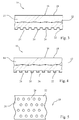
- a conveyor belt 10 shown in cross-section in FIG. 1 is generally constructed in such a way that, in its interior volume region, it has a reinforcing structure 12 formed, for example, by a woven fabric or other fiber material.
- This reinforcing structure 12 is embedded or surrounded on both sides by building material 14 of the conveyor belt 10.
- This building material 14 may comprise, for example, polymer material, such as Polyurtehan. It may be composed of various materials in multiple layers, and it may be provided that different types of construction materials are used on both sides of the reinforcement structure 12. It can further be provided that the reinforcing structure 12 is encapsulated by the building material 14 or on both sides or on one side of the layered or laminated construction material 14 carries.
- the conveyor belt 10 basically constructed as described above with the reinforcing structure 12 and the building material 14 has a web material side 16 at which this conveyor belt 10 comes into contact with a web material contacting surface 18 with the web material to be produced, e.g. Paper or cardboard, or the starting material for it.
- a web material contacting surface 18 with the web material to be produced, e.g. Paper or cardboard, or the starting material for it.
- the conveyor belt 10 On the opposite side, ie a machine side 20, the conveyor belt 10 has a machine contact surface 22. With this machine contact surface 22, the conveyor belt 10 is in contact with several of these leading or also for movement driving rollers.
- liquid In the production of web material, such as paper or cardboard, in various processing stations, especially in pressing stations, liquid, generally water, is pressed out of the construction material of the web material. This accumulates primarily at the web material contact surface 18. In order not to press this liquid back into the web material, ie to avoid rewetting, and to be able to discharge it reliably from the web material, depressions, not shown, can be provided on the web material side 16 in FIG. 1, in which this liquid can accumulate. In the course of a manufacturing process, however, such liquid will also reach the rear side, that is to say the machine side 20 of the conveyor belt 10. Also dissolved from the building material of the web material out particles can get into the area of the machine side 20 together with the liquid. This could lead to the problem that by reducing the static friction coefficient, a required drive friction contact with one or more drive rollers can no longer be ensured and thus a drive slip occurs between a drive roller and the conveyor belt 10.
- the conveyor belt 10 is configured on its machine side 20 with a plurality of depressions 24.
- These recesses 24 may be configured groove-like and may, as shown in FIG. 1, approximately perpendicular to the transverse direction CMD of the conveyor belt 10, ie substantially in a longitudinal direction of the orthogonal to the plane of FIG. 1 Conveyor belt 10, extend.
- the depressions 24 may be arranged in a regular pattern, as shown in FIG. 1, ie they may also have a uniform mutual distance, or they may be in an irregular, statistically distributed pattern in terms of distance and orientation and optionally also dimensioning be provided.
- the depression depth d of these depressions 24 should be at least 50 ⁇ m. It has proved to be advantageous if this depression depth is in the range of 100 ⁇ m to 1000 ⁇ m, preferably between 200 ⁇ m and 800 ⁇ m. In this way, it can be ensured that substantially all of the liquid occurring and / or accumulating on the machine side 20 and particles also contained therein can be received in the depressions 24 and thus a reliable frictional contact of the machine contact surface 22 with drive rollers is present.
- the materials received in the depressions 24 should advantageously be removed, for example after passing through a pressing station, by using a cleaning device, such as a cleaning scraper or a cleaning brush, from the machine side 20 of the conveyor belt 10.
- a cleaning device such as a cleaning scraper or a cleaning brush
- the surface roughness in the region of the machine contact surface 22 is preferably at a value Rz of at least 30 ⁇ m, it is advantageous if the surface roughness in the region of the depression surfaces 26 is most preferred at a value of at most Rz 8 ⁇ m, preferably below Rz 5 ⁇ m is below Rz 4 microns.
- Such a smooth surface ensures the easy detachment of existing in the region of the depressions 24 materials.
- an adhesion-reducing layer This can be constructed for example of Teflon (PTFE).
- PTFE Teflon
- the conveyor belt 10 with the depressions 24, the entire machine side 20, ie the depression surfaces 26 and the machine contact surface 22, with this adhesion-reducing material with one especially for the coating the sinking surfaces 26 are coated with a suitable or desired layer thickness.
- the machine side 20 can then be subjected to a roughening or removal treatment in which the adhesion-reducing material deposited on the machine contact surface 22 is then removed again and the desired surface roughness is provided in the region of the machine contact surface 22.
- FIG. 2 An alternative embodiment of a conveyor belt is shown in Fig. 2.
- the same components or subregions of the conveyor belt are denoted by the same reference numerals, as in Fig. 1.
- Fig. 2 a difference in the shape of the depressions 24 is present.
- the recognizable in Fig. 2 recesses 24 are tapered away in the direction of the machine contact surface 22 away. That is, an opening dimension decreases in the direction from this machine contact surface 22 toward a sinking ground. While in the embodiment shown in Fig. 1, this dimensional decrease or tapering shape is provided with a rounded, for example, circular, oval or elliptical contour, is provided for the embodiment in Fig. 2, a substantially cone-like tapered contour of the depressions 24.
- depressions 24 with tapering shape away from the machine contact surface 22 ensures that where these depressions 24 adjoin the machine contact surface 22, comparatively large openings are formed, such that existing on the machine side 20 and in the depressions 24 material to be recorded quickly and reliably passes into these depressions 24.
- FIG. 24 A further modification with regard to the shaping of the depressions 24 is shown in FIG. It can be seen here that the depressions 24 in the illustrated section are approximately rectangular or square, ie in the direction of the machine contact surface 22 away an approximately constant Einenkungsabunk, in elongated configuration, in particular in the longitudinal direction of the conveyor belt 10 elongated configuration, ie approximately constant width exhibit. This leads to a very stable, with pressure loads only slightly deforming and thus the predetermined volume of the depressions 24 approximately retaining arrangement.
- the depressions 24 are designed to widen in the direction away from the machine contact surface 22.
- a conical or dovetail-like widening shape of the depressions 24 is provided.
- the advantage of this embodiment variant is that, with a comparatively large volume of the depressions 24, the interruptions in the machine contact surface 22 generated by these depressions 24 are significantly lower than, for example, in the embodiment shown in FIGS. 1 and 2. That is to say, the total machine contact surface 22 provided with a construction shown in FIG. 4 for a conveyor belt 10 is larger for the same dimensioning of the conveyor belt 10. This leads to a relief of the conveyor belt 10 on the machine contact surface, since occurring pressure loads are distributed over a larger machine contact surface. Especially with regard to the wear occurring during operation, this is a very advantageous embodiment.
- Fig. 5 is a plan view of the machine side 20 and the machine contact surface 22 of a conveyor belt 10 can be seen. Again, only a partial section of such a conveyor belt 10 is shown.
- the depressions 24 are not elongated in a longitudinal direction of the conveyor belt 10 or a transverse direction of the conveyor belt 10, but are formed as discrete depressions. These can, as shown in Fig. 5, be designed with a circular shape, but may for example also be oval, square, elliptical or the like. Of course, these discrete depressions 24, as previously shown, may be tapered away in the direction away from the machine contact surface 22, be widening or be formed with approximately constant dimension. These discrete depressions 24 can be distributed on the machine side 20 in a regular pattern, as can be seen in FIG. 5, or can be distributed statistically, whereby care can also be taken in the statistical distribution that for a given area unit a certain total volume the depressions 24 is provided.
- the depressions in a partial region of their extension length can extend, for example, with a constant dimension, while in a subsequent region a tapering or possibly widening contour is predetermined.
- a combination of expanding and tapering portions of respective depressions is possible, as well as the combination depressions of different shapes on one and the same conveyor belt.
- the construction according to the invention of a conveyor belt 10 thus ensures, in a simple and reliable manner, that the running properties of the conveyor belt 10 are not impaired by the leading or driving rollers on the rear side, ie the machine side, the conveyor belt.
- sufficient friction contact of the machine contact surface with the leading or driving beams can be ensured.
- by designing the depressions it can be ensured that materials accumulating therein, such as e.g. Water and particles emerging from the stock material for the web material can be easily released from the depressions, so that a gradual closing of these depressions over the service life can be prevented.
- Fig. 1 depressions 24 in adaptation to those in use to expected ambient conditions can be selected. Also, the way in which these depressions can be provided, for example by molding, pressing, material lifting, drilling or the like, can be selected so that the depressions then formed are optimally adapted for each existing operating conditions.
Landscapes
- Belt Conveyors (AREA)
- Structure Of Belt Conveyors (AREA)
Applications Claiming Priority (1)
| Application Number | Priority Date | Filing Date | Title |
|---|---|---|---|
| DE102006024343A DE102006024343A1 (de) | 2006-05-24 | 2006-05-24 | Transportband für eine Maschine zur Herstellung von Bahnmaterial und Verfahren zur Herstellung eines derartigen Transportbandes |
Publications (3)
| Publication Number | Publication Date |
|---|---|
| EP1870514A2 true EP1870514A2 (fr) | 2007-12-26 |
| EP1870514A3 EP1870514A3 (fr) | 2013-09-25 |
| EP1870514B1 EP1870514B1 (fr) | 2021-06-30 |
Family
ID=38622162
Family Applications (1)
| Application Number | Title | Priority Date | Filing Date |
|---|---|---|---|
| EP07105720.2A Active EP1870514B1 (fr) | 2006-05-24 | 2007-04-05 | Bande de transport pour une machine destinée à la fabrication de matériaux en bande et méthode de réalisation d'une telle bande de transport |
Country Status (3)
| Country | Link |
|---|---|
| US (1) | US7776188B2 (fr) |
| EP (1) | EP1870514B1 (fr) |
| DE (1) | DE102006024343A1 (fr) |
Cited By (2)
| Publication number | Priority date | Publication date | Assignee | Title |
|---|---|---|---|---|
| CN103046422A (zh) * | 2011-10-12 | 2013-04-17 | 市川株式会社 | 传送湿纸幅用皮带 |
| EP3404140A1 (fr) * | 2017-05-15 | 2018-11-21 | Heimbach GmbH & Co. KG | Bande de transfert ou de presse à sabot pour une machine à papier, utilisation de la bande dans une machine à papier et procédé de fabrication de la bande |
Families Citing this family (1)
| Publication number | Priority date | Publication date | Assignee | Title |
|---|---|---|---|---|
| JP5044301B2 (ja) * | 2007-06-25 | 2012-10-10 | イチカワ株式会社 | 製紙機械用シュープレスベルトおよびその製造方法 |
Family Cites Families (11)
| Publication number | Priority date | Publication date | Assignee | Title |
|---|---|---|---|---|
| US3613258A (en) * | 1969-09-15 | 1971-10-19 | Draper Brothers Co | Felt for papermaking machine |
| CS198481B1 (en) * | 1977-05-20 | 1980-06-30 | Cestmir Balcar | Multilayer felt,method of and apparatus for manufacturing same |
| FI75620C (fi) * | 1982-04-01 | 1988-07-11 | Tampella Oy Ab | Laongzonspress foer en pappersmaskin. |
| US4740409A (en) * | 1987-03-31 | 1988-04-26 | Lefkowitz Leonard R | Nonwoven fabric and method of manufacture |
| US4842905A (en) * | 1988-02-03 | 1989-06-27 | Asten Group, Inc. | Tessellated papermakers fabric and elements for producing the same |
| DE4202731C2 (de) * | 1992-01-31 | 1997-04-17 | Voith Gmbh J M | Preßmantel für eine Schuhpresse |
| JPH1150386A (ja) * | 1997-06-30 | 1999-02-23 | Christian Schiel | 改善された両面構造を有する抄紙用フェルト及びその製造方法 |
| US6183601B1 (en) * | 1999-02-03 | 2001-02-06 | Kimberly-Clark Worldwide, Inc. | Method of calendering a sheet material web carried by a fabric |
| US6726809B2 (en) * | 2001-09-26 | 2004-04-27 | Albany International Corp. | Industrial process fabric |
| DE50313235D1 (de) * | 2003-08-13 | 2010-12-16 | Heimbach Gmbh & Co | Papiermaschinenbespannung |
| DE102005039301A1 (de) * | 2005-08-19 | 2007-02-22 | Voith Patent Gmbh | Transferband |
-
2006
- 2006-05-24 DE DE102006024343A patent/DE102006024343A1/de not_active Withdrawn
-
2007
- 2007-04-05 EP EP07105720.2A patent/EP1870514B1/fr active Active
- 2007-05-16 US US11/749,451 patent/US7776188B2/en not_active Expired - Fee Related
Cited By (6)
| Publication number | Priority date | Publication date | Assignee | Title |
|---|---|---|---|---|
| CN103046422A (zh) * | 2011-10-12 | 2013-04-17 | 市川株式会社 | 传送湿纸幅用皮带 |
| EP2581493A1 (fr) * | 2011-10-12 | 2013-04-17 | Ichikawa Co., Ltd. | Bande pour transférer une bande humide |
| US8709214B2 (en) | 2011-10-12 | 2014-04-29 | Ichikawa Co., Ltd. | Belt for transferring wet web |
| CN103046422B (zh) * | 2011-10-12 | 2015-04-22 | 市川株式会社 | 传送湿纸幅用皮带 |
| EP3404140A1 (fr) * | 2017-05-15 | 2018-11-21 | Heimbach GmbH & Co. KG | Bande de transfert ou de presse à sabot pour une machine à papier, utilisation de la bande dans une machine à papier et procédé de fabrication de la bande |
| CN108867139A (zh) * | 2017-05-15 | 2018-11-23 | 亨巴赫有限公司&两合公司 | 造纸机的转移或靴型压带、在造纸机中的用途及制造方法 |
Also Published As
| Publication number | Publication date |
|---|---|
| US7776188B2 (en) | 2010-08-17 |
| US20070275214A1 (en) | 2007-11-29 |
| DE102006024343A1 (de) | 2007-11-29 |
| EP1870514B1 (fr) | 2021-06-30 |
| EP1870514A3 (fr) | 2013-09-25 |
Similar Documents
| Publication | Publication Date | Title |
|---|---|---|
| EP2167726A1 (fr) | Bande pour une machine de fabrication de materiau en bande, notamment de papier ou de carton, et procede de fabrication d'une telle bande | |
| EP0100085A2 (fr) | Rouleau, notamment rouleau pour machine à papier | |
| EP1870514B1 (fr) | Bande de transport pour une machine destinée à la fabrication de matériaux en bande et méthode de réalisation d'une telle bande de transport | |
| EP2360314B1 (fr) | Bande de transfert | |
| EP1813715A1 (fr) | Bande de transport | |
| EP2072669B1 (fr) | Bande pour une machine destinée à la fabrication de matériaux en bande et procédé de fabrication d'une telle bande | |
| EP3404140B1 (fr) | Bande de transfert ou de presse à sabot pour une machine à papier, utilisation de la bande dans une machine à papier et procédé de fabrication de la bande | |
| DE102016102567B4 (de) | Verbundwalze und Verwendung der Verbundwalze | |
| EP3597821B1 (fr) | Dispositif de tension pour une machine destinée à la fabrication d'une bande de matière fibreuse | |
| DE102008042690B4 (de) | Breitstreckwalze mit aufgerauter, wendelförmiger Oberfläche | |
| WO2008068015A1 (fr) | Ligne de coupe rotative | |
| DE102015217941A1 (de) | Pressmmantel und Verfahren zur Herstellung eines solchen | |
| EP1837438A2 (fr) | Machine de fabrication de matériaux roulant, en particulier du papier ou du carton, et procédé de traitement d'une surface d'une bande de transport dans une machine destinée à la fabrication de matériaux roulants | |
| EP1813716A1 (fr) | Bande de transport | |
| DE3913110C2 (fr) | ||
| WO2013149795A1 (fr) | Tamis | |
| DE102024101687A1 (de) | Verfahren zur abfallfreien Herstellung einer Bespannung für eine Faserstoffbahn-Maschine und eine solche Bespannung | |
| DE102006057254A1 (de) | Transportband für eine Maschine zur Herstellung von Bahnmaterial, insbesondere Papier oder Karton | |
| DE102006003708A1 (de) | Transportband | |
| AT10291U1 (de) | Reibungs- bzw. verschleissarme lagervorrichtung | |
| DE212016000259U1 (de) | Pressband, Anordnung in einem langen Nip und Herstellungssystem eines Pressbands | |
| DE102006003704A1 (de) | Transportband | |
| DE102023121031A1 (de) | Formiersieb mit unperforierten Längsstreifen | |
| WO2025171972A1 (fr) | Élément de déshydratation, et procédé de production et utilisation d'un tel élément de déshydratation | |
| DE10227848A1 (de) | Walze einer Papiermaschine und Verfahren zu ihrer Herstellung |
Legal Events
| Date | Code | Title | Description |
|---|---|---|---|
| PUAI | Public reference made under article 153(3) epc to a published international application that has entered the european phase |
Free format text: ORIGINAL CODE: 0009012 |
|
| AK | Designated contracting states |
Kind code of ref document: A2 Designated state(s): AT BE BG CH CY CZ DE DK EE ES FI FR GB GR HU IE IS IT LI LT LU LV MC MT NL PL PT RO SE SI SK TR |
|
| AX | Request for extension of the european patent |
Extension state: AL BA HR MK YU |
|
| PUAL | Search report despatched |
Free format text: ORIGINAL CODE: 0009013 |
|
| AK | Designated contracting states |
Kind code of ref document: A3 Designated state(s): AT BE BG CH CY CZ DE DK EE ES FI FR GB GR HU IE IS IT LI LT LU LV MC MT NL PL PT RO SE SI SK TR |
|
| AX | Request for extension of the european patent |
Extension state: AL BA HR MK RS |
|
| RIC1 | Information provided on ipc code assigned before grant |
Ipc: D21F 3/02 20060101ALI20130822BHEP Ipc: D21F 1/10 20060101AFI20130822BHEP Ipc: D21F 7/08 20060101ALI20130822BHEP |
|
| REG | Reference to a national code |
Ref country code: DE Ref legal event code: R108 |
|
| AKY | No designation fees paid | ||
| REG | Reference to a national code |
Ref country code: DE Ref legal event code: R108 Effective date: 20140527 |
|
| 17P | Request for examination filed |
Effective date: 20140714 |
|
| RBV | Designated contracting states (corrected) |
Designated state(s): AT BE BG CH CY CZ DE DK EE ES FI FR GB GR HU IE IS IT LI LT LU LV MC MT NL PL PT RO SE SI SK TR |
|
| 17Q | First examination report despatched |
Effective date: 20140808 |
|
| STAA | Information on the status of an ep patent application or granted ep patent |
Free format text: STATUS: EXAMINATION IS IN PROGRESS |
|
| RAP1 | Party data changed (applicant data changed or rights of an application transferred) |
Owner name: VOITH PATENT GMBH |
|
| GRAP | Despatch of communication of intention to grant a patent |
Free format text: ORIGINAL CODE: EPIDOSNIGR1 |
|
| STAA | Information on the status of an ep patent application or granted ep patent |
Free format text: STATUS: GRANT OF PATENT IS INTENDED |
|
| INTG | Intention to grant announced |
Effective date: 20210204 |
|
| GRAS | Grant fee paid |
Free format text: ORIGINAL CODE: EPIDOSNIGR3 |
|
| GRAA | (expected) grant |
Free format text: ORIGINAL CODE: 0009210 |
|
| STAA | Information on the status of an ep patent application or granted ep patent |
Free format text: STATUS: THE PATENT HAS BEEN GRANTED |
|
| AK | Designated contracting states |
Kind code of ref document: B1 Designated state(s): AT BE BG CH CY CZ DE DK EE ES FI FR GB GR HU IE IS IT LI LT LU LV MC MT NL PL PT RO SE SI SK TR |
|
| REG | Reference to a national code |
Ref country code: GB Ref legal event code: FG4D Free format text: NOT ENGLISH Ref country code: CH Ref legal event code: EP |
|
| REG | Reference to a national code |
Ref country code: AT Ref legal event code: REF Ref document number: 1406432 Country of ref document: AT Kind code of ref document: T Effective date: 20210715 |
|
| REG | Reference to a national code |
Ref country code: DE Ref legal event code: R096 Ref document number: 502007016954 Country of ref document: DE |
|
| REG | Reference to a national code |
Ref country code: IE Ref legal event code: FG4D Free format text: LANGUAGE OF EP DOCUMENT: GERMAN |
|
| REG | Reference to a national code |
Ref country code: FI Ref legal event code: FGE |
|
| REG | Reference to a national code |
Ref country code: LT Ref legal event code: MG9D |
|
| PG25 | Lapsed in a contracting state [announced via postgrant information from national office to epo] |
Ref country code: BG Free format text: LAPSE BECAUSE OF FAILURE TO SUBMIT A TRANSLATION OF THE DESCRIPTION OR TO PAY THE FEE WITHIN THE PRESCRIBED TIME-LIMIT Effective date: 20210930 |
|
| REG | Reference to a national code |
Ref country code: NL Ref legal event code: MP Effective date: 20210630 |
|
| PG25 | Lapsed in a contracting state [announced via postgrant information from national office to epo] |
Ref country code: GR Free format text: LAPSE BECAUSE OF FAILURE TO SUBMIT A TRANSLATION OF THE DESCRIPTION OR TO PAY THE FEE WITHIN THE PRESCRIBED TIME-LIMIT Effective date: 20211001 Ref country code: LV Free format text: LAPSE BECAUSE OF FAILURE TO SUBMIT A TRANSLATION OF THE DESCRIPTION OR TO PAY THE FEE WITHIN THE PRESCRIBED TIME-LIMIT Effective date: 20210630 Ref country code: SE Free format text: LAPSE BECAUSE OF FAILURE TO SUBMIT A TRANSLATION OF THE DESCRIPTION OR TO PAY THE FEE WITHIN THE PRESCRIBED TIME-LIMIT Effective date: 20210630 |
|
| PG25 | Lapsed in a contracting state [announced via postgrant information from national office to epo] |
Ref country code: ES Free format text: LAPSE BECAUSE OF FAILURE TO SUBMIT A TRANSLATION OF THE DESCRIPTION OR TO PAY THE FEE WITHIN THE PRESCRIBED TIME-LIMIT Effective date: 20210630 Ref country code: NL Free format text: LAPSE BECAUSE OF FAILURE TO SUBMIT A TRANSLATION OF THE DESCRIPTION OR TO PAY THE FEE WITHIN THE PRESCRIBED TIME-LIMIT Effective date: 20210630 Ref country code: RO Free format text: LAPSE BECAUSE OF FAILURE TO SUBMIT A TRANSLATION OF THE DESCRIPTION OR TO PAY THE FEE WITHIN THE PRESCRIBED TIME-LIMIT Effective date: 20210630 Ref country code: PT Free format text: LAPSE BECAUSE OF FAILURE TO SUBMIT A TRANSLATION OF THE DESCRIPTION OR TO PAY THE FEE WITHIN THE PRESCRIBED TIME-LIMIT Effective date: 20211102 Ref country code: SK Free format text: LAPSE BECAUSE OF FAILURE TO SUBMIT A TRANSLATION OF THE DESCRIPTION OR TO PAY THE FEE WITHIN THE PRESCRIBED TIME-LIMIT Effective date: 20210630 Ref country code: CZ Free format text: LAPSE BECAUSE OF FAILURE TO SUBMIT A TRANSLATION OF THE DESCRIPTION OR TO PAY THE FEE WITHIN THE PRESCRIBED TIME-LIMIT Effective date: 20210630 Ref country code: EE Free format text: LAPSE BECAUSE OF FAILURE TO SUBMIT A TRANSLATION OF THE DESCRIPTION OR TO PAY THE FEE WITHIN THE PRESCRIBED TIME-LIMIT Effective date: 20210630 |
|
| PG25 | Lapsed in a contracting state [announced via postgrant information from national office to epo] |
Ref country code: PL Free format text: LAPSE BECAUSE OF FAILURE TO SUBMIT A TRANSLATION OF THE DESCRIPTION OR TO PAY THE FEE WITHIN THE PRESCRIBED TIME-LIMIT Effective date: 20210630 |
|
| REG | Reference to a national code |
Ref country code: DE Ref legal event code: R097 Ref document number: 502007016954 Country of ref document: DE |
|
| PG25 | Lapsed in a contracting state [announced via postgrant information from national office to epo] |
Ref country code: DK Free format text: LAPSE BECAUSE OF FAILURE TO SUBMIT A TRANSLATION OF THE DESCRIPTION OR TO PAY THE FEE WITHIN THE PRESCRIBED TIME-LIMIT Effective date: 20210630 |
|
| PLBE | No opposition filed within time limit |
Free format text: ORIGINAL CODE: 0009261 |
|
| STAA | Information on the status of an ep patent application or granted ep patent |
Free format text: STATUS: NO OPPOSITION FILED WITHIN TIME LIMIT |
|
| 26N | No opposition filed |
Effective date: 20220331 |
|
| PG25 | Lapsed in a contracting state [announced via postgrant information from national office to epo] |
Ref country code: IT Free format text: LAPSE BECAUSE OF FAILURE TO SUBMIT A TRANSLATION OF THE DESCRIPTION OR TO PAY THE FEE WITHIN THE PRESCRIBED TIME-LIMIT Effective date: 20210630 |
|
| REG | Reference to a national code |
Ref country code: CH Ref legal event code: PL |
|
| REG | Reference to a national code |
Ref country code: BE Ref legal event code: MM Effective date: 20220430 |
|
| PG25 | Lapsed in a contracting state [announced via postgrant information from national office to epo] |
Ref country code: MC Free format text: LAPSE BECAUSE OF FAILURE TO SUBMIT A TRANSLATION OF THE DESCRIPTION OR TO PAY THE FEE WITHIN THE PRESCRIBED TIME-LIMIT Effective date: 20210630 Ref country code: LU Free format text: LAPSE BECAUSE OF NON-PAYMENT OF DUE FEES Effective date: 20220405 Ref country code: LI Free format text: LAPSE BECAUSE OF NON-PAYMENT OF DUE FEES Effective date: 20220430 Ref country code: FR Free format text: LAPSE BECAUSE OF NON-PAYMENT OF DUE FEES Effective date: 20220430 Ref country code: CH Free format text: LAPSE BECAUSE OF NON-PAYMENT OF DUE FEES Effective date: 20220430 |
|
| PG25 | Lapsed in a contracting state [announced via postgrant information from national office to epo] |
Ref country code: BE Free format text: LAPSE BECAUSE OF NON-PAYMENT OF DUE FEES Effective date: 20220430 |
|
| PG25 | Lapsed in a contracting state [announced via postgrant information from national office to epo] |
Ref country code: LT Free format text: LAPSE BECAUSE OF FAILURE TO SUBMIT A TRANSLATION OF THE DESCRIPTION OR TO PAY THE FEE WITHIN THE PRESCRIBED TIME-LIMIT Effective date: 20210630 Ref country code: IE Free format text: LAPSE BECAUSE OF NON-PAYMENT OF DUE FEES Effective date: 20220405 |
|
| REG | Reference to a national code |
Ref country code: AT Ref legal event code: MM01 Ref document number: 1406432 Country of ref document: AT Kind code of ref document: T Effective date: 20220405 |
|
| PG25 | Lapsed in a contracting state [announced via postgrant information from national office to epo] |
Ref country code: AT Free format text: LAPSE BECAUSE OF NON-PAYMENT OF DUE FEES Effective date: 20220405 |
|
| PGFP | Annual fee paid to national office [announced via postgrant information from national office to epo] |
Ref country code: FI Payment date: 20230419 Year of fee payment: 17 |
|
| PG25 | Lapsed in a contracting state [announced via postgrant information from national office to epo] |
Ref country code: HU Free format text: LAPSE BECAUSE OF FAILURE TO SUBMIT A TRANSLATION OF THE DESCRIPTION OR TO PAY THE FEE WITHIN THE PRESCRIBED TIME-LIMIT; INVALID AB INITIO Effective date: 20070405 |
|
| PG25 | Lapsed in a contracting state [announced via postgrant information from national office to epo] |
Ref country code: CY Free format text: LAPSE BECAUSE OF FAILURE TO SUBMIT A TRANSLATION OF THE DESCRIPTION OR TO PAY THE FEE WITHIN THE PRESCRIBED TIME-LIMIT Effective date: 20210630 |
|
| PG25 | Lapsed in a contracting state [announced via postgrant information from national office to epo] |
Ref country code: TR Free format text: LAPSE BECAUSE OF FAILURE TO SUBMIT A TRANSLATION OF THE DESCRIPTION OR TO PAY THE FEE WITHIN THE PRESCRIBED TIME-LIMIT Effective date: 20210630 |
|
| PG25 | Lapsed in a contracting state [announced via postgrant information from national office to epo] |
Ref country code: MT Free format text: LAPSE BECAUSE OF FAILURE TO SUBMIT A TRANSLATION OF THE DESCRIPTION OR TO PAY THE FEE WITHIN THE PRESCRIBED TIME-LIMIT Effective date: 20210630 |
|
| PG25 | Lapsed in a contracting state [announced via postgrant information from national office to epo] |
Ref country code: FI Free format text: LAPSE BECAUSE OF NON-PAYMENT OF DUE FEES Effective date: 20240405 |
|
| PG25 | Lapsed in a contracting state [announced via postgrant information from national office to epo] |
Ref country code: FI Free format text: LAPSE BECAUSE OF NON-PAYMENT OF DUE FEES Effective date: 20240405 |
|
| PGFP | Annual fee paid to national office [announced via postgrant information from national office to epo] |
Ref country code: DE Payment date: 20250422 Year of fee payment: 19 |
|
| PGFP | Annual fee paid to national office [announced via postgrant information from national office to epo] |
Ref country code: GB Payment date: 20250418 Year of fee payment: 19 |