EP1870536B1 - Verstellbare klemme zur sicherung von schalungstafeln - Google Patents
Verstellbare klemme zur sicherung von schalungstafeln Download PDFInfo
- Publication number
- EP1870536B1 EP1870536B1 EP06743431.6A EP06743431A EP1870536B1 EP 1870536 B1 EP1870536 B1 EP 1870536B1 EP 06743431 A EP06743431 A EP 06743431A EP 1870536 B1 EP1870536 B1 EP 1870536B1
- Authority
- EP
- European Patent Office
- Prior art keywords
- shaped members
- intermediate support
- adjustable clamp
- clamp
- pins
- Prior art date
- Legal status (The legal status is an assumption and is not a legal conclusion. Google has not performed a legal analysis and makes no representation as to the accuracy of the status listed.)
- Expired - Lifetime
Links
Images



Classifications
-
- E—FIXED CONSTRUCTIONS
- E04—BUILDING
- E04G—SCAFFOLDING; FORMS; SHUTTERING; BUILDING IMPLEMENTS OR AIDS, OR THEIR USE; HANDLING BUILDING MATERIALS ON THE SITE; REPAIRING, BREAKING-UP OR OTHER WORK ON EXISTING BUILDINGS
- E04G17/00—Connecting or other auxiliary members for forms, falsework structures, or shutterings
- E04G17/04—Connecting or fastening means for metallic forming or stiffening elements, e.g. for connecting metallic elements to non-metallic elements
- E04G17/042—Connecting or fastening means for metallic forming or stiffening elements, e.g. for connecting metallic elements to non-metallic elements being tensioned by threaded elements
-
- E—FIXED CONSTRUCTIONS
- E04—BUILDING
- E04G—SCAFFOLDING; FORMS; SHUTTERING; BUILDING IMPLEMENTS OR AIDS, OR THEIR USE; HANDLING BUILDING MATERIALS ON THE SITE; REPAIRING, BREAKING-UP OR OTHER WORK ON EXISTING BUILDINGS
- E04G17/00—Connecting or other auxiliary members for forms, falsework structures, or shutterings
- E04G17/04—Connecting or fastening means for metallic forming or stiffening elements, e.g. for connecting metallic elements to non-metallic elements
-
- E—FIXED CONSTRUCTIONS
- E04—BUILDING
- E04G—SCAFFOLDING; FORMS; SHUTTERING; BUILDING IMPLEMENTS OR AIDS, OR THEIR USE; HANDLING BUILDING MATERIALS ON THE SITE; REPAIRING, BREAKING-UP OR OTHER WORK ON EXISTING BUILDINGS
- E04G9/00—Forming or shuttering elements for general use
- E04G9/02—Forming boards or similar elements
- E04G2009/023—Forming boards or similar elements with edge protection
- E04G2009/025—Forming boards or similar elements with edge protection by a flange of the board's frame
-
- Y—GENERAL TAGGING OF NEW TECHNOLOGICAL DEVELOPMENTS; GENERAL TAGGING OF CROSS-SECTIONAL TECHNOLOGIES SPANNING OVER SEVERAL SECTIONS OF THE IPC; TECHNICAL SUBJECTS COVERED BY FORMER USPC CROSS-REFERENCE ART COLLECTIONS [XRACs] AND DIGESTS
- Y10—TECHNICAL SUBJECTS COVERED BY FORMER USPC
- Y10T—TECHNICAL SUBJECTS COVERED BY FORMER US CLASSIFICATION
- Y10T24/00—Buckles, buttons, clasps, etc.
- Y10T24/44—Clasp, clip, support-clamp, or required component thereof
- Y10T24/44291—Clasp, clip, support-clamp, or required component thereof including pivoted gripping member
- Y10T24/44496—Clasp, clip, support-clamp, or required component thereof including pivoted gripping member with operator means for moving pivoted member
- Y10T24/44504—Threaded cylindrical rod and mating cavity
-
- Y—GENERAL TAGGING OF NEW TECHNOLOGICAL DEVELOPMENTS; GENERAL TAGGING OF CROSS-SECTIONAL TECHNOLOGIES SPANNING OVER SEVERAL SECTIONS OF THE IPC; TECHNICAL SUBJECTS COVERED BY FORMER USPC CROSS-REFERENCE ART COLLECTIONS [XRACs] AND DIGESTS
- Y10—TECHNICAL SUBJECTS COVERED BY FORMER USPC
- Y10T—TECHNICAL SUBJECTS COVERED BY FORMER US CLASSIFICATION
- Y10T403/00—Joints and connections
- Y10T403/32—Articulated members
- Y10T403/32254—Lockable at fixed position
- Y10T403/32426—Plural distinct positions
Definitions
- the present invention is intended to disclose a clamp of adjustable type for securing the frames of panels for shuttering concrete, for walls and the like.
- clamps for securing the frames of the panels for shuttering concrete is well known and numerous types having different characteristics have been used in the course of time.
- a clamp for securing concrete panels must basically comply with characteristics of mechanical strength, partly because of the efforts which it must perform during its functioning and partly because of the rough treatment to which concrete shuttering members are customarily subjected during building work.
- clamps of this type must have characteristics of easy and rapid application to the frames of the shuttering panels, in order to facilitate handling.
- GB 04721 discloses a cramp for supporting the sheeting for concrete constructions which has two jaws articulated on an intermediate body from which a bracket is held carrying an arm to embrace a bearer for the sheeting and another arm carrying a roller acting on the bearer. GB 04721 does disclose the preamble of claim 1.
- the present invention is intended to disclose .an adjustable clamp which makes it possible to obtain, with a minimum number of parts and with simplified manufacturing methods for same, a clamp adjustable within wide limits so that it is possible to use it on different types of panels having widths substantially different from the profile sections of the frames, so that a clamp is obtained which is highly effective and of relatively reduced cost.
- the present invention provides an adjustable clamp according to claim 1, whereby it provides for the clamp to be constituted simply by three basic members, two of which are the actual members of the clamp, and substantially L-shaped, and the third is an intermediate support member on which they are articulated and which is intended to receive the profile sections of the frames of the shuttering panels to be joined.
- the clamp is complemented simply by pins for articulating the two L-shaped members on the intermediate support and optionally by a threaded rod with its wing nut.
- the L-shaped members may be constituted by a base of sheet steel simply cut and pressed, equipped with an assembly of ribs to increase their strength, avoiding any type of welding or other operations which increase the complexity and cost of the clamp and at the same time raise problems regarding protection against corrosion.
- the adjustable clamp of the present invention is constituted by two L-shaped members which may assume the structure of double laminar arms, parallel to each other, two of which have ends of a shape complementary to the lateral cavities which the profile sections of the frames of the shuttering boards have in order to permit easy coupling thereof, while the other arms of the L-shaped members are articulated with one another by means of a transverse pin.
- the two L-shaped members are further articulated by two other points with respective transverse pins.
- the other elongated holes two have their axes parallel to the central elongated hole which has been described and the other two are elongated holes in the shape of an arc of a circle, so that the centre and the radius of this arc is such that the path of the central point of the protuberances for contact with the profile sections approximates to a straight line parallel to the intermediate member, so that it is possible to obtain one of the essential characteristics of the clamp of the present invention, which is that the displacement of the L-shaped members for the adjustment of the clamp to different widths of the profile sections to be clamped occurs without changing the relative height of the bearing points with the aforesaid profile sections, thereby obtaining the characteristic of adjustability of the clamp to different widths of profiles, all of which have the same shape of the lateral securing cavities.
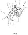
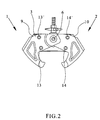
- the clamp is constituted fundamentally by two L-shaped members 1 and 2 which have the structure of double arms parallel to one another, such as those shown by the numbers 3, 3', and 4, 4' for the member 1.
- the end of the arm 3 has an end stamping 5 which overlaps with the corresponding non-stamped arm of the member 2 and is traversed by the central pivot pin 6.
- the stamping 5' is provided on the arm of the member 2, and it is the arm 3' of the member 1 which is flat, without stamping.
- the ends of the arms 4 and 4' have profiles 7 of a shape complementary to the profile sections of the frames of the shuttering panels which they are to clamp, preferably reinforced by means of auxiliary plates that are welded or joined in some other way, as may be observed in Figure 1 .
- the two L-shaped members 1 and 2 are articulated on an intermediate support 8 which is intended to receive the profile sections which form part of the frames of the shuttering panels to be joined, as shown by way of example in Figure 6 .
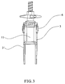
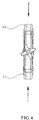
- Said intermediate support 8 is preferably tubular and has its ends 9 and 10 cut in a bevel and surrounded by the end bridges 11 and 12 for joining the double arms of the L-shaped members 1 and 2.
- the articulation of the L-shaped members is effected by means of the central pin 6 and four other pins, two for each L-shaped member, which have been indicated by the numbers 13 and 13' for the member 1, and 14, 14' for the L-shaped member 2. All the pivot pins pass through the intermediate support 8 by means of corresponding elongated holes, as can be seen in Figures 6 to 8 .
- the central pin 6 passes through the inside of a straight elongated hole 15 parallel to the axis of the threaded actuating rod 16 and, therefore, perpendicular to the axis of the intermediate support 8.
- Said pin 6 also passes through an end head 17 of the threaded rod 16, which carries coupled on it a wing nut 26 which permits the adjustment of the clamp, bearing on the side 27 of the intermediate support 8.
- the pins 13' and 14' move within respective straight elongated holes 18 and 19 which are parallel to the elongated hole 15, and finally the pins 13 and 14 move within respective curved elongated holes 20 and 21 which are in the shape of an arc of a circle, so that the centre and the radius of this arc is such that the trajectory of the central point of the protuberances 22 and 23 for contact with the profile sections approximates to a straight line 24 parallel to the intermediate member.
- Figure 6 shows diagrammatically two profile sections 28 and 29 of respective frames of shuttering panels, these not having been shown in the rest of the views for the purpose of simplification.
Landscapes
- Engineering & Computer Science (AREA)
- Architecture (AREA)
- Mechanical Engineering (AREA)
- Civil Engineering (AREA)
- Structural Engineering (AREA)
- Forms Removed On Construction Sites Or Auxiliary Members Thereof (AREA)
- Moulds, Cores, Or Mandrels (AREA)
- Clamps And Clips (AREA)
Claims (2)
- Einstellbare Klemme zur Sicherung von Schaltafeln, wobei die einstellbare Klemme zwei im Wesentlichen L-förmige Elemente (1, 2) umfasst, die an einem Zwischenträger (8), an dem Profilabschnitte (28, 29) von Rahmen der einzuklemmenden Tafeln anliegen, gelenkig angebracht sind, wobei die L-förmigen Elemente (1, 2) ferner einen zentralen Stift (6), um die zwei L-förmigen Elemente (1, 2) gelenkig anzubringen, einen ersten Stiftsatz (13, 13') für das erste L-förmige Element (1) und einen zweiten Stiftsatz (14, 14') für das zweite L-förmige Element (2) umfassen, wobei:der Zwischenträger (8) das Folgende umfasst:- ein verlängertes Loch (15) zum Durchtritt eines zentralen Stifts (6), um die zwei L-förmigen Elemente (1, 2) gelenkig anzubringen, wobei das verlängerte Loch (15) rechtwinkelig zu einer Längsachse des Zwischenträgers (8) verläuft;- zwei gekrümmte verlängerte Löcher (20, 21) in Kreisbogenform, um das zweite Stiftpaar (13, 14) der L-förmigen Elemente (1, 2) aufzunehmen,dadurch gekennzeichnet, dass der Zwischenträger (8) das Folgende umfasst:- zwei gerade verlängerte Löcher (18, 19), entlang derer das erste Stiftpaar (13', 14') der L-förmigen Elemente (1, 2) gleiten kann, wobei die zwei geraden verlängerten Löcher (18, 19) parallel zu dem verlängerten Loch (15) verlaufen,und dadurch gekennzeichnet, dass jedes der im Wesentlichen L-förmigen Elemente (1, 2) das Folgende umfasst:- zugehörige Stiftpaare (13, 13'), (14, 14'), die durch zugehörige gerade und gekrümmte verlängerte Löcher (20, 18) und (21, 19) der L-förmigen Elemente (1, 2) hindurchtreten,dadurch gekennzeichnet, dass der zentrale Stift (6), um die zwei L-förmigen Elemente (1, 2) gelenkig miteinander zu verbinden, durch das Innere des verlängerten Lochs (15) in dem Zwischenträger (8) hindurchtritt,und darüber hinaus dadurch gekennzeichnet, dass sowohl der Mittelpunkt als auch der Radius des Kreisbogens von den gekrümmten verlängerten Löchern (20, 21) in Kreisbogenform derart gestaltet sind, dass sie die Einstellung der einstellbaren Klemme derart erlauben, dass die Angriffspunkte (22, 23) der L-förmigen Elemente (1, 2) der Klemme an den Profilabschnitten (28, 29) auf einer geraden Linie parallel zur Längsachse des Zwischenträgers (8) verschoben werden, um die Einstellung der einstellbaren Klemme derart zu erlauben, dass die Angriffspunkte (22, 23) der L-förmigen Elemente (1, 2) der einstellbaren Klemme an den Profilabschnitten (28, 29), für unterschiedliche Breiten der Profilabschnitte, parallel in Bezug auf die Seite des Zwischenträgers (8), an der die obenerwähnten Profilabschnitte (28, 29) anliegen, bleiben.
- Einstellbare Klemme zur Sicherung von Schaltafeln nach Anspruch 1, dadurch gekennzeichnet, dass der zentrale Stift (6), um die zwei L-förmigen Elemente (1, 2) gelenkig anzubringen, durch einen Kopf (17) einer Gewindestange (16) hindurchtritt, die mit dem Zwischenträger (8) verbunden ist, wobei die Gewindestange eine Festellmutter umfasst, die auf die Seiten des Zwischenträgers (8) einwirkt.
Priority Applications (1)
| Application Number | Priority Date | Filing Date | Title |
|---|---|---|---|
| PL06743431T PL1870536T3 (pl) | 2005-04-11 | 2006-04-10 | Regulowany zacisk do mocowania paneli szalunkowych |
Applications Claiming Priority (2)
| Application Number | Priority Date | Filing Date | Title |
|---|---|---|---|
| ES200500833A ES2245264B1 (es) | 2005-04-11 | 2005-04-11 | Mordaza ajustable para sujecion de paneles de encofrado. |
| PCT/ES2006/000172 WO2006108894A1 (es) | 2005-04-11 | 2006-04-10 | Mordaza ajustable para sujeción de paneles de encofrado. |
Publications (3)
| Publication Number | Publication Date |
|---|---|
| EP1870536A1 EP1870536A1 (de) | 2007-12-26 |
| EP1870536A4 EP1870536A4 (de) | 2011-09-28 |
| EP1870536B1 true EP1870536B1 (de) | 2016-03-23 |
Family
ID=35601603
Family Applications (1)
| Application Number | Title | Priority Date | Filing Date |
|---|---|---|---|
| EP06743431.6A Expired - Lifetime EP1870536B1 (de) | 2005-04-11 | 2006-04-10 | Verstellbare klemme zur sicherung von schalungstafeln |
Country Status (9)
| Country | Link |
|---|---|
| US (1) | US7703358B2 (de) |
| EP (1) | EP1870536B1 (de) |
| BR (1) | BRPI0609403A2 (de) |
| ES (2) | ES2245264B1 (de) |
| MA (1) | MA29419B1 (de) |
| MX (1) | MX2007010641A (de) |
| PL (1) | PL1870536T3 (de) |
| UA (1) | UA88946C2 (de) |
| WO (1) | WO2006108894A1 (de) |
Families Citing this family (29)
| Publication number | Priority date | Publication date | Assignee | Title |
|---|---|---|---|---|
| ES2249188B1 (es) * | 2005-04-11 | 2006-12-01 | Ingenieria De Encofrados Y Servicios, S.L. | Mordaza para sujecion de paneles de encofrado. |
| CA2694437C (en) * | 2007-07-26 | 2016-09-06 | Glenn R. Buttermann | Segmental orthopedic device for spinal elongation and for treatment of scoliosis |
| US9204908B2 (en) * | 2007-07-26 | 2015-12-08 | Dynamic Spine, Llc | Segmental orthopedic device for spinal elongation and for treatment of scoliosis |
| EP2765257A1 (de) * | 2008-03-13 | 2014-08-13 | WOLF Holding GmbH | Leiterkorb |
| JP5078928B2 (ja) * | 2009-02-27 | 2012-11-21 | 三菱重工業株式会社 | 反転装置 |
| US8573576B2 (en) * | 2009-06-26 | 2013-11-05 | Intuitive Research And Technology Corporation | Clamp for single-handed operation |
| JP2011079657A (ja) * | 2009-10-09 | 2011-04-21 | Murata Machinery Ltd | 移載装置、移載方法 |
| EP2579795B1 (de) | 2010-06-10 | 2018-10-31 | Globus Medical, Inc. | Uniplanare niedrigprofil-knochenschraube |
| US20120126079A1 (en) * | 2010-11-23 | 2012-05-24 | Acist Medical Systems, Inc. | Bedrail clamp |
| USD646137S1 (en) * | 2010-11-24 | 2011-10-04 | Rockler Companies, Inc. | 3 way edge clamp |
| US20120248673A1 (en) * | 2011-04-01 | 2012-10-04 | Yung Yang Jen | Point-welding clamp |
| US8528888B2 (en) | 2011-05-27 | 2013-09-10 | Gregory A. Header | Flanged material and standing seam clamp |
| US9375180B2 (en) | 2012-04-29 | 2016-06-28 | Acist Medical Systems, Inc. | Universal pressure transducer mounting device |
| USD695585S1 (en) * | 2013-03-18 | 2013-12-17 | Christopher Bryan Trussell | Hold-down clamp |
| MX388543B (es) * | 2014-03-06 | 2025-03-20 | Hubbell Inc | Sistema sujetador de molde, de accionamiento eléctrico, para soldeo por reacción exotérmica. |
| US9585806B2 (en) | 2015-06-11 | 2017-03-07 | Acist Medical Systems, Inc. | Variable rate bedrail clamp |
| USD798697S1 (en) * | 2016-03-26 | 2017-10-03 | Francois Roy | Expanding corner for an art canvas frame |
| USD796943S1 (en) * | 2016-03-26 | 2017-09-12 | Francois Roy | Expanding corner for an art canvas frame |
| US12195961B2 (en) | 2016-06-24 | 2025-01-14 | Apache Industrial Services, Inc. | Formwork system |
| US10472823B2 (en) | 2016-06-24 | 2019-11-12 | Apache Industrial Services, Inc. | Formwork system |
| US11976483B2 (en) | 2016-06-24 | 2024-05-07 | Apache Industrial Services, Inc | Modular posts of an integrated construction system |
| US11306492B2 (en) | 2016-06-24 | 2022-04-19 | Apache Industrial Services, Inc | Load bearing components and safety deck of an integrated construction system |
| US11624196B2 (en) | 2016-06-24 | 2023-04-11 | Apache Industrial Services, Inc | Connector end fitting for an integrated construction system |
| US10938192B2 (en) * | 2018-06-08 | 2021-03-02 | Panduit Corp. | Cable cleat assembly |
| US10923892B2 (en) * | 2018-06-08 | 2021-02-16 | Panduit Corp. | Cable cleat assembly |
| CN109098444B (zh) * | 2018-08-16 | 2020-10-16 | 江苏省苏中建设集团股份有限公司 | 建筑模板 |
| WO2020159455A1 (en) * | 2019-01-30 | 2020-08-06 | Urti̇m Kalip Ve İskele Si̇stemleri̇ Sanayi̇ Ve Ti̇caret Anoni̇m Şi̇rketi̇ | Locking mechanism for the panel formwork systems |
| US10823329B1 (en) | 2019-05-29 | 2020-11-03 | 1514 Tech, Llc | Clamp and computing device stand incorporating same |
| CN114482521B (zh) * | 2022-01-27 | 2023-07-14 | 南通四建集团有限公司 | 一种适用于建筑土建施工的预留孔模板 |
Family Cites Families (13)
| Publication number | Priority date | Publication date | Assignee | Title |
|---|---|---|---|---|
| GB191404721A (en) | 1914-02-24 | 1915-02-24 | John Adamson | A Cramp for Supporting the Sheeting used in Applying Concrete. |
| US2183680A (en) * | 1938-04-12 | 1939-12-19 | William T Kahliff | Clamp for grounding electrical equipment |
| US2432139A (en) * | 1944-12-15 | 1947-12-09 | Dill Mfg Co | Portable tire repair unit |
| US2422865A (en) * | 1945-01-04 | 1947-06-24 | James I Tucker | Quick detachable hook |
| US2543017A (en) * | 1945-06-23 | 1951-02-27 | John A Hagan | Quick release clamp |
| US2915096A (en) * | 1957-04-08 | 1959-12-01 | Mooney Edward | Hand clamp |
| US3039161A (en) * | 1960-08-29 | 1962-06-19 | Paul L Gagnon | Clamp |
| US3984798A (en) * | 1974-11-21 | 1976-10-05 | International Telephone And Telegraph Corporation | Hotstick applicator for fault indicator cores |
| US4541155A (en) * | 1983-04-07 | 1985-09-17 | Gagnon Paul L | Portable beam clamp |
| EP0201887B2 (de) * | 1985-05-14 | 1996-03-20 | THYSSEN HÜNNEBECK GmbH | Vorrichtung zum Verbinden und Zusammenhalten nebeneinander angeordneter Schalungselemente wie Schaltafeln |
| DE8814208U1 (de) * | 1988-11-12 | 1989-01-05 | Maier, Josef, 7619 Steinach | Klammer zum Verbinden von Schaltafeln |
| ES2063635B1 (es) * | 1992-04-09 | 1997-05-01 | Ulma S Coop | Grapa de union de marcos portantes para tableros de encofrados modulares. |
| US5598775A (en) * | 1995-10-04 | 1997-02-04 | Lsi Logic Corporation | Centering lid seal clip apparatus |
-
2005
- 2005-04-11 ES ES200500833A patent/ES2245264B1/es not_active Expired - Lifetime
-
2006
- 2006-04-10 MX MX2007010641A patent/MX2007010641A/es active IP Right Grant
- 2006-04-10 PL PL06743431T patent/PL1870536T3/pl unknown
- 2006-04-10 BR BRPI0609403-1A patent/BRPI0609403A2/pt not_active Application Discontinuation
- 2006-04-10 WO PCT/ES2006/000172 patent/WO2006108894A1/es not_active Ceased
- 2006-04-10 US US11/911,285 patent/US7703358B2/en active Active
- 2006-04-10 UA UAA200710261A patent/UA88946C2/ru unknown
- 2006-04-10 ES ES06743431.6T patent/ES2574583T3/es not_active Expired - Lifetime
- 2006-04-10 EP EP06743431.6A patent/EP1870536B1/de not_active Expired - Lifetime
-
2007
- 2007-10-30 MA MA30346A patent/MA29419B1/fr unknown
Also Published As
| Publication number | Publication date |
|---|---|
| US20080193204A1 (en) | 2008-08-14 |
| MA29419B1 (fr) | 2008-04-01 |
| ES2245264A1 (es) | 2005-12-16 |
| US7703358B2 (en) | 2010-04-27 |
| UA88946C2 (ru) | 2009-12-10 |
| ES2245264B1 (es) | 2007-03-16 |
| WO2006108894A8 (es) | 2007-10-25 |
| ES2574583T3 (es) | 2016-06-20 |
| EP1870536A4 (de) | 2011-09-28 |
| MX2007010641A (es) | 2007-10-08 |
| PL1870536T3 (pl) | 2017-10-31 |
| WO2006108894A1 (es) | 2006-10-19 |
| EP1870536A1 (de) | 2007-12-26 |
| BRPI0609403A2 (pt) | 2010-04-06 |
Similar Documents
| Publication | Publication Date | Title |
|---|---|---|
| EP1870536B1 (de) | Verstellbare klemme zur sicherung von schalungstafeln | |
| EP1870535B1 (de) | Klemme zur sicherung von schalungstafeln | |
| AT394960B (de) | Mobiles abbrennstumpf-schweissaggregat | |
| KR20170013219A (ko) | 크레인, 특히 오버헤드 또는 갠트리 크레인용 크레인 거더, 및 그러한 거더를 포함하는 크레인 | |
| EP2292873B1 (de) | Justierbares Paneel zum Umschalen von gewölbten Wänden | |
| DE102012200458A1 (de) | Schienenführung für mobile Schweiß- oder Schneidgeräte und Verfahren zu ihrer Herstellung | |
| CN114227126A (zh) | 用于生产钢结构的夹持式拼装装置 | |
| EP1736602B1 (de) | Schweissmaschine zum Verschweissen von Schienen eines Gleises | |
| CN210255803U (zh) | 一种铝型材生产加工用固定夹紧装置 | |
| KR20130142929A (ko) | 시스템 서포트 | |
| CN202010751U (zh) | 钢筋折弯机 | |
| CN219864145U (zh) | 张紧组件 | |
| US7269990B1 (en) | Portable frame puller | |
| WO2025023838A1 (en) | Jig for aligning knuckles of door hinges | |
| CN114211187B (zh) | 一种用于钢结构桥梁焊接施工的送料装置 | |
| CN210457187U (zh) | 一种抓手 | |
| JP3145030B2 (ja) | クランプ装置 | |
| EP1625898A1 (de) | Vorrichtung zum Herstellen von Rohren | |
| CN220347584U (zh) | 一种钢筋对接辅助装置 | |
| DE102006016879B4 (de) | Verbindungsvorrichtung zum Verbinden zweier Schalungselemente | |
| CN112176868A (zh) | 一种架设主桁的焊接式下弦杆的定位方法 | |
| EP0475344B1 (de) | Richtgerät | |
| WO2006099487A2 (en) | Clamp for interconnecting components of concrete forming apparatus | |
| CN224092840U (zh) | 一种精确定位的大跨度组合截面贝雷梁 | |
| CN116181085B (zh) | 张紧组件 |
Legal Events
| Date | Code | Title | Description |
|---|---|---|---|
| PUAI | Public reference made under article 153(3) epc to a published international application that has entered the european phase |
Free format text: ORIGINAL CODE: 0009012 |
|
| 17P | Request for examination filed |
Effective date: 20070827 |
|
| AK | Designated contracting states |
Kind code of ref document: A1 Designated state(s): AT BE BG CH CY CZ DE DK EE ES FI FR GB GR HU IE IS IT LI LT LU LV MC NL PL PT RO SE SI SK TR |
|
| DAX | Request for extension of the european patent (deleted) | ||
| A4 | Supplementary search report drawn up and despatched |
Effective date: 20110829 |
|
| RIC1 | Information provided on ipc code assigned before grant |
Ipc: E04G 17/04 20060101AFI20110823BHEP |
|
| 17Q | First examination report despatched |
Effective date: 20150212 |
|
| GRAP | Despatch of communication of intention to grant a patent |
Free format text: ORIGINAL CODE: EPIDOSNIGR1 |
|
| INTG | Intention to grant announced |
Effective date: 20151013 |
|
| GRAS | Grant fee paid |
Free format text: ORIGINAL CODE: EPIDOSNIGR3 |
|
| GRAA | (expected) grant |
Free format text: ORIGINAL CODE: 0009210 |
|
| AK | Designated contracting states |
Kind code of ref document: B1 Designated state(s): AT BE BG CH CY CZ DE DK EE ES FI FR GB GR HU IE IS IT LI LT LU LV MC NL PL PT RO SE SI SK TR |
|
| REG | Reference to a national code |
Ref country code: GB Ref legal event code: FG4D |
|
| REG | Reference to a national code |
Ref country code: CH Ref legal event code: EP |
|
| REG | Reference to a national code |
Ref country code: AT Ref legal event code: REF Ref document number: 783321 Country of ref document: AT Kind code of ref document: T Effective date: 20160415 |
|
| REG | Reference to a national code |
Ref country code: IE Ref legal event code: FG4D |
|
| REG | Reference to a national code |
Ref country code: DE Ref legal event code: R096 Ref document number: 602006048345 Country of ref document: DE |
|
| REG | Reference to a national code |
Ref country code: ES Ref legal event code: FG2A Ref document number: 2574583 Country of ref document: ES Kind code of ref document: T3 Effective date: 20160620 |
|
| REG | Reference to a national code |
Ref country code: LT Ref legal event code: MG4D |
|
| REG | Reference to a national code |
Ref country code: NL Ref legal event code: MP Effective date: 20160323 |
|
| PG25 | Lapsed in a contracting state [announced via postgrant information from national office to epo] |
Ref country code: GR Free format text: LAPSE BECAUSE OF FAILURE TO SUBMIT A TRANSLATION OF THE DESCRIPTION OR TO PAY THE FEE WITHIN THE PRESCRIBED TIME-LIMIT Effective date: 20160624 Ref country code: FI Free format text: LAPSE BECAUSE OF FAILURE TO SUBMIT A TRANSLATION OF THE DESCRIPTION OR TO PAY THE FEE WITHIN THE PRESCRIBED TIME-LIMIT Effective date: 20160323 |
|
| REG | Reference to a national code |
Ref country code: AT Ref legal event code: MK05 Ref document number: 783321 Country of ref document: AT Kind code of ref document: T Effective date: 20160323 |
|
| PG25 | Lapsed in a contracting state [announced via postgrant information from national office to epo] |
Ref country code: NL Free format text: LAPSE BECAUSE OF FAILURE TO SUBMIT A TRANSLATION OF THE DESCRIPTION OR TO PAY THE FEE WITHIN THE PRESCRIBED TIME-LIMIT Effective date: 20160323 Ref country code: LV Free format text: LAPSE BECAUSE OF FAILURE TO SUBMIT A TRANSLATION OF THE DESCRIPTION OR TO PAY THE FEE WITHIN THE PRESCRIBED TIME-LIMIT Effective date: 20160323 Ref country code: SE Free format text: LAPSE BECAUSE OF FAILURE TO SUBMIT A TRANSLATION OF THE DESCRIPTION OR TO PAY THE FEE WITHIN THE PRESCRIBED TIME-LIMIT Effective date: 20160323 Ref country code: LT Free format text: LAPSE BECAUSE OF FAILURE TO SUBMIT A TRANSLATION OF THE DESCRIPTION OR TO PAY THE FEE WITHIN THE PRESCRIBED TIME-LIMIT Effective date: 20160323 Ref country code: BE Free format text: LAPSE BECAUSE OF NON-PAYMENT OF DUE FEES Effective date: 20160430 |
|
| PG25 | Lapsed in a contracting state [announced via postgrant information from national office to epo] |
Ref country code: IS Free format text: LAPSE BECAUSE OF FAILURE TO SUBMIT A TRANSLATION OF THE DESCRIPTION OR TO PAY THE FEE WITHIN THE PRESCRIBED TIME-LIMIT Effective date: 20160723 Ref country code: EE Free format text: LAPSE BECAUSE OF FAILURE TO SUBMIT A TRANSLATION OF THE DESCRIPTION OR TO PAY THE FEE WITHIN THE PRESCRIBED TIME-LIMIT Effective date: 20160323 |
|
| REG | Reference to a national code |
Ref country code: DE Ref legal event code: R119 Ref document number: 602006048345 Country of ref document: DE |
|
| PG25 | Lapsed in a contracting state [announced via postgrant information from national office to epo] |
Ref country code: RO Free format text: LAPSE BECAUSE OF FAILURE TO SUBMIT A TRANSLATION OF THE DESCRIPTION OR TO PAY THE FEE WITHIN THE PRESCRIBED TIME-LIMIT Effective date: 20160323 Ref country code: SK Free format text: LAPSE BECAUSE OF FAILURE TO SUBMIT A TRANSLATION OF THE DESCRIPTION OR TO PAY THE FEE WITHIN THE PRESCRIBED TIME-LIMIT Effective date: 20160323 Ref country code: AT Free format text: LAPSE BECAUSE OF FAILURE TO SUBMIT A TRANSLATION OF THE DESCRIPTION OR TO PAY THE FEE WITHIN THE PRESCRIBED TIME-LIMIT Effective date: 20160323 Ref country code: CZ Free format text: LAPSE BECAUSE OF FAILURE TO SUBMIT A TRANSLATION OF THE DESCRIPTION OR TO PAY THE FEE WITHIN THE PRESCRIBED TIME-LIMIT Effective date: 20160323 Ref country code: PT Free format text: LAPSE BECAUSE OF FAILURE TO SUBMIT A TRANSLATION OF THE DESCRIPTION OR TO PAY THE FEE WITHIN THE PRESCRIBED TIME-LIMIT Effective date: 20160725 |
|
| REG | Reference to a national code |
Ref country code: CH Ref legal event code: PL |
|
| PG25 | Lapsed in a contracting state [announced via postgrant information from national office to epo] |
Ref country code: BE Free format text: LAPSE BECAUSE OF FAILURE TO SUBMIT A TRANSLATION OF THE DESCRIPTION OR TO PAY THE FEE WITHIN THE PRESCRIBED TIME-LIMIT Effective date: 20160323 Ref country code: IT Free format text: LAPSE BECAUSE OF FAILURE TO SUBMIT A TRANSLATION OF THE DESCRIPTION OR TO PAY THE FEE WITHIN THE PRESCRIBED TIME-LIMIT Effective date: 20160323 |
|
| REG | Reference to a national code |
Ref country code: IE Ref legal event code: MM4A |
|
| PLBE | No opposition filed within time limit |
Free format text: ORIGINAL CODE: 0009261 |
|
| REG | Reference to a national code |
Ref country code: FR Ref legal event code: ST Effective date: 20161230 |
|
| STAA | Information on the status of an ep patent application or granted ep patent |
Free format text: STATUS: NO OPPOSITION FILED WITHIN TIME LIMIT |
|
| PG25 | Lapsed in a contracting state [announced via postgrant information from national office to epo] |
Ref country code: DE Free format text: LAPSE BECAUSE OF NON-PAYMENT OF DUE FEES Effective date: 20161101 Ref country code: CH Free format text: LAPSE BECAUSE OF NON-PAYMENT OF DUE FEES Effective date: 20160430 Ref country code: FR Free format text: LAPSE BECAUSE OF NON-PAYMENT OF DUE FEES Effective date: 20160523 Ref country code: LI Free format text: LAPSE BECAUSE OF NON-PAYMENT OF DUE FEES Effective date: 20160430 Ref country code: DK Free format text: LAPSE BECAUSE OF FAILURE TO SUBMIT A TRANSLATION OF THE DESCRIPTION OR TO PAY THE FEE WITHIN THE PRESCRIBED TIME-LIMIT Effective date: 20160323 |
|
| PG25 | Lapsed in a contracting state [announced via postgrant information from national office to epo] |
Ref country code: BG Free format text: LAPSE BECAUSE OF FAILURE TO SUBMIT A TRANSLATION OF THE DESCRIPTION OR TO PAY THE FEE WITHIN THE PRESCRIBED TIME-LIMIT Effective date: 20160623 |
|
| 26N | No opposition filed |
Effective date: 20170102 |
|
| GBPC | Gb: european patent ceased through non-payment of renewal fee |
Effective date: 20160623 |
|
| PG25 | Lapsed in a contracting state [announced via postgrant information from national office to epo] |
Ref country code: GB Free format text: LAPSE BECAUSE OF NON-PAYMENT OF DUE FEES Effective date: 20160623 Ref country code: IE Free format text: LAPSE BECAUSE OF NON-PAYMENT OF DUE FEES Effective date: 20160410 Ref country code: SI Free format text: LAPSE BECAUSE OF FAILURE TO SUBMIT A TRANSLATION OF THE DESCRIPTION OR TO PAY THE FEE WITHIN THE PRESCRIBED TIME-LIMIT Effective date: 20160323 |
|
| PG25 | Lapsed in a contracting state [announced via postgrant information from national office to epo] |
Ref country code: HU Free format text: LAPSE BECAUSE OF FAILURE TO SUBMIT A TRANSLATION OF THE DESCRIPTION OR TO PAY THE FEE WITHIN THE PRESCRIBED TIME-LIMIT; INVALID AB INITIO Effective date: 20060410 Ref country code: CY Free format text: LAPSE BECAUSE OF FAILURE TO SUBMIT A TRANSLATION OF THE DESCRIPTION OR TO PAY THE FEE WITHIN THE PRESCRIBED TIME-LIMIT Effective date: 20160323 |
|
| PG25 | Lapsed in a contracting state [announced via postgrant information from national office to epo] |
Ref country code: TR Free format text: LAPSE BECAUSE OF FAILURE TO SUBMIT A TRANSLATION OF THE DESCRIPTION OR TO PAY THE FEE WITHIN THE PRESCRIBED TIME-LIMIT Effective date: 20160323 Ref country code: LU Free format text: LAPSE BECAUSE OF NON-PAYMENT OF DUE FEES Effective date: 20160410 Ref country code: MC Free format text: LAPSE BECAUSE OF FAILURE TO SUBMIT A TRANSLATION OF THE DESCRIPTION OR TO PAY THE FEE WITHIN THE PRESCRIBED TIME-LIMIT Effective date: 20160323 |
|
| PGFP | Annual fee paid to national office [announced via postgrant information from national office to epo] |
Ref country code: PL Payment date: 20250205 Year of fee payment: 20 |
|
| PGFP | Annual fee paid to national office [announced via postgrant information from national office to epo] |
Ref country code: ES Payment date: 20250505 Year of fee payment: 20 |