EP1870631B1 - Lampe d'éclairage à LED équippée d'un boîtier compact et à orientation multidirectionnelle - Google Patents
Lampe d'éclairage à LED équippée d'un boîtier compact et à orientation multidirectionnelle Download PDFInfo
- Publication number
- EP1870631B1 EP1870631B1 EP07354027A EP07354027A EP1870631B1 EP 1870631 B1 EP1870631 B1 EP 1870631B1 EP 07354027 A EP07354027 A EP 07354027A EP 07354027 A EP07354027 A EP 07354027A EP 1870631 B1 EP1870631 B1 EP 1870631B1
- Authority
- EP
- European Patent Office
- Prior art keywords
- lamp according
- case
- selector switch
- lighting module
- fixing plate
- Prior art date
- Legal status (The legal status is an assumption and is not a legal conclusion. Google has not performed a legal analysis and makes no representation as to the accuracy of the status listed.)
- Active
Links
Images


Classifications
-
- F—MECHANICAL ENGINEERING; LIGHTING; HEATING; WEAPONS; BLASTING
- F21—LIGHTING
- F21L—LIGHTING DEVICES OR SYSTEMS THEREOF, BEING PORTABLE OR SPECIALLY ADAPTED FOR TRANSPORTATION
- F21L4/00—Electric lighting devices with self-contained electric batteries or cells
- F21L4/04—Electric lighting devices with self-contained electric batteries or cells characterised by the provision of a light source housing portion adjustably fixed to the remainder of the device
- F21L4/045—Pocket lamps
-
- F—MECHANICAL ENGINEERING; LIGHTING; HEATING; WEAPONS; BLASTING
- F21—LIGHTING
- F21L—LIGHTING DEVICES OR SYSTEMS THEREOF, BEING PORTABLE OR SPECIALLY ADAPTED FOR TRANSPORTATION
- F21L4/00—Electric lighting devices with self-contained electric batteries or cells
- F21L4/02—Electric lighting devices with self-contained electric batteries or cells characterised by the provision of two or more light sources
- F21L4/022—Pocket lamps
- F21L4/027—Pocket lamps the light sources being a LED
-
- F—MECHANICAL ENGINEERING; LIGHTING; HEATING; WEAPONS; BLASTING
- F21—LIGHTING
- F21V—FUNCTIONAL FEATURES OR DETAILS OF LIGHTING DEVICES OR SYSTEMS THEREOF; STRUCTURAL COMBINATIONS OF LIGHTING DEVICES WITH OTHER ARTICLES, NOT OTHERWISE PROVIDED FOR
- F21V23/00—Arrangement of electric circuit elements in or on lighting devices
- F21V23/04—Arrangement of electric circuit elements in or on lighting devices the elements being switches
- F21V23/0414—Arrangement of electric circuit elements in or on lighting devices the elements being switches specially adapted to be used with portable lighting devices
-
- F—MECHANICAL ENGINEERING; LIGHTING; HEATING; WEAPONS; BLASTING
- F21—LIGHTING
- F21Y—INDEXING SCHEME ASSOCIATED WITH SUBCLASSES F21K, F21L, F21S and F21V, RELATING TO THE FORM OR THE KIND OF THE LIGHT SOURCES OR OF THE COLOUR OF THE LIGHT EMITTED
- F21Y2115/00—Light-generating elements of semiconductor light sources
- F21Y2115/10—Light-emitting diodes [LED]
Definitions
- the invention relates to a portable lighting lamp comprising an LED lighting module, an operating mode selection switch, and a power supply battery, the assembly being housed in a housing which is coupled to a mounting plate by a ball joint.
- the document EP-A-1445532 discloses a front electric lamp comprising an LED lighting module arranged on the front side, and an ignition control switch located on the upper side face of the housing.
- a mounting plate of an elastic is shaped U-shaped stirrup hinged to the housing around a horizontal axis to orient the lamp from bottom to top.
- the lamp is powered by three cylindrical batteries housed inside the housing. The size of such a housing is quite important, and the orientation of the lamp is limited to a simple pivoting movement about a horizontal axis.
- the object of the invention is to provide an LED lighting lamp having a compact footprint, allowing selection of different modes of operation, and a multidirectional orientation.
- the lighting lamp according to the invention is characterized in that the LED lighting module and the switch are arranged side by side on the front face, and that the ball joint is arranged in a housing provided at the base of the housing between the switch and the lighting module.
- the size of the lamp in the direction of the depth is very compact, and the ball joint allows a multidirectional orientation of the plate relative to the housing of the lamp, as well as the mounting on different supports.
- the platen also serves as a cover that can be manipulated by turning over on the rear face or on the front of the housing.
- the switch is rotatably mounted on an axis perpendicular to the front face, and comprises a gripping tab equipped with a movable guide pin along a circular groove formed in the narrow side face of the housing.
- the groove is provided with a plurality of indexing notches for determining successive angular positions relating to the various modes of operation.
- the lighting module has three white LEDs arranged at the vertices of a triangle, and a central red LED.
- the housing advantageously has a flattened shape.
- the LEDs are powered by means of two stacked flat batteries, which can be accessed by means of a rotatable cover integrated into the back of the housing.
- the plate further comprises means for the introduction of an elastic or a winder, and is equipped with a spring clip made of steel wire for attachment to a support means.
- an LED lighting lamp 10 comprises a housing 11 mounted on a plate 12 by a ball joint 13 allowing a multidirectional orientation.
- the housing 11 is compact in the depth direction, and encloses at least one circular shaped button cell 14 accessible by means of a rotatable cover 16 integrated in a circular opening 17 formed in the rear face 15.
- the lighting module 18 is housed in a recess 19 of the front face 20 of the housing 11, and comprises three LEDs 21 of white colors arranged at the vertices of a triangle, and a red LED 22 inserted in the center of the three white LEDs 21 .
- a multi-position rotary switch 23 causes a wiper contact on an electronic board (not shown) to select the various modes of operation of the lamp 10.
- the switch 23 is arranged next to the lighting module 18 while being rotatably mounted on an axis 24 perpendicular to the front face 20.
- the axis 24 of the switch 23 extends parallel to the light beam emitted by the LEDs 21, 22 .
- Actuation of the switch 23 is effected by means of a gripping tab 25, which is equipped with a guide pin 26 moving along a circular groove 27 formed in the narrow side face of the housing 11.
- the groove 27 comprises a plurality of indexing notches 33 cooperating with the lug 26 to determine the successive angular positions relating to the various modes of incremental operation.
- the ball joint 13 is integral with the plate 12, and is engaged in a housing 28 of complementary shape, provided at the base of the housing 11 opposite the gripping tab 25 when it is in the end position of run off locked.
- the plate 12 has a flattened shape on the outer side, and a bowl 29 on the inner side. Two loops 30 split in the plate 12 allow the assembly and disassembly of an elastic to form a headlamp.
- the plate 12 is additionally provided with two orifices 31 for the use of a winder, and a spring clip 32 made of stainless steel wire for hanging on any type of support, for example a strap, pocket , elastic, belt, etc ...
- the incremental displacement by pivoting of the switch 23 makes it possible to obtain the various modes of operation of the LEDs 21, 22.
- At each stable position of the switch 23 in a notch 33 corresponds a specific mode of illumination.
- the ball joint 13 allows a multidirectional orientation of the plate 13 relative to the housing 11 of the lamp 10, and the mounting on different supports.
- the plate 12 can bear against the cup side 29 on the front face 20 so as to cover the lighting module 18 with LEDs 21, 22, and the switch 23 (see figures 3 and 7 ).
- the housing 11 of the lamp is tilted 90 ° downwards, followed by a rotation of 180 ° with respect to the axis of the foot of the ball 13, and finally a rise of 90 °.
- the flattened outer side of the plate 12 also allows to put the lamp on a flat surface (table, or other).
- the plate 12 can also be plated on the rear face of the housing 11 ( Figures 2 and 1 ). It can be associated with a rubber band, a winder, and can be clipped on any support thanks to the spring clip 32.
- the lighting module 18 may be constituted by a different number of LEDs, or by a single power LED.
- the rotary switch 23 can also be replaced by a push button pulses protruding from the front face 20.
Landscapes
- Engineering & Computer Science (AREA)
- General Engineering & Computer Science (AREA)
- Arrangement Of Elements, Cooling, Sealing, Or The Like Of Lighting Devices (AREA)
- Non-Portable Lighting Devices Or Systems Thereof (AREA)
- Lighting Device Outwards From Vehicle And Optical Signal (AREA)
- Arrangements Of Lighting Devices For Vehicle Interiors, Mounting And Supporting Thereof, Circuits Therefore (AREA)
- Switches With Compound Operations (AREA)
Description
- L'invention est relative à une lampe d'éclairage portative comprenant un module d'éclairage à LED, un commutateur de sélection du mode de fonctionnement, et une pile d'alimentation, l'ensemble étant logé dans un boîtier lequel est accouplé à une platine de fixation par une liaison à rotule.
- Le document
EP-A-1445532 décrit une lampe électrique frontale comprenant un module d'éclairage à LED agencé sur la face avant, et un interrupteur de commande d'allumage situé sur la face latérale supérieure du boîtier. Une platine de fixation d'un élastique est conformée en étrier en U articulé au boîtier autour d'un axe horizontal permettant d'orienter la lampe de bas en haut. La lampe est alimentée par trois piles cylindriques logées à l'intérieur du boîtier. L'encombrement d'un tel boîtier est assez important, et l'orientation de la lampe est limitée à un simple mouvement de pivotement autour d'un axe horizontal. - On a déjà proposé dans les documents
US 2003/0179570 etUS 6672972 de monter une lampe d'éclairage sur un support au moyen d'une articulation à rotule. Outre la longueur importante du boîtier, l'articulation à rotule est située à l'arrière du boîtier, et le support est conformé selon un clip ou une pince. - L'objet de l'invention consiste à réaliser une lampe d'éclairage à LED ayant un encombrement compact, autorisant une sélection de différents modes de fonctionnement, et une orientation multidirectionnelle.
- La lampe d'éclairage selon l'invention est caractérisée en ce que le module d'éclairage à LED et le commutateur sont disposés côte à côte sur la face avant, et que la liaison à rotule est agencée dans un logement prévu à la base du boîtier entre le commutateur et le module d'éclairage.
- L'encombrement de la lampe dans le sens de la profondeur est très compact, et la liaison à rotule permet une orientation multidirectionnelle de la platine par rapport au boîtier de la lampe, ainsi que le montage sur différents supports. La platine sert également de couvercle pouvant être manipulé par retournement sur la face arrière ou sur la face avant du boîtier.
- Selon un mode de réalisation préférentiel, le commutateur est monté à rotation sur un axe perpendiculaire à la face avant, et comporte une patte de préhension équipée d'un ergot de guidage mobile le long d'une rainure circulaire aménagée dans la face latérale étroite du boîtier. La rainure est munie d'une pluralité de crans d'indexage pour déterminer des positions angulaires successives relatives aux divers modes de fonctionnement. Le module d'éclairage comporte trois LED blanches disposées aux sommets d'un triangle, et une LED rouge centrale.
- Le boîtier possède avantageusement une forme aplatie. L'alimentation des LED s'effectue au moyen de deux piles plates empilées, accessibles au moyen d'un couvercle rotatif intégré dans la face arrière du boîtier.
- La platine comporte en plus des moyens pour la mise en place d'un élastique ou d'un enrouleur, et est équipée d'un clip à ressort en fil d'acier pour l'accrochage à un moyen support.
- D'autres avantages et caractéristiques ressortiront plus clairement de la description qui va suivre d'un mode particulier de réalisation de l'invention donné à titre d'exemple non limitatif et représenté aux dessins annexés, dans lesquels :
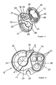
- la
figure 1 est une vue en perspective de la lampe d'éclairage selon l'invention, la platine étant rangée contre la face arrière du boîtier ; - les
figures 2 et3 montrent respectivement des vues en perspective de la face arrière et de la face avant de la lampe, la platine étant représentée en position déployée ; - la
figure 4 est une vue de face de la lampe de lafigure 1 , la platine avec sa liaison à rotule n'étant pas représentées ; - la
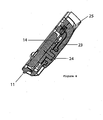
figure 5 est une vue en perspective de profil de la lampe, montrant la rainure avec les crans d'indexage du commutateur; - la
figure 6 illustre une vue en coupe selon la ligne 6-6 de lafigure 4 ; - la
figure 7 montre une vue de profil de la lampe avec la platine rangée en position de couvercle sur la face avant pour la protection des LED. - En référence aux figures, une lampe 10 d'éclairage à LED comporte un boîtier 11 monté sur une platine 12 par une liaison à rotule 13 permettant une orientation multidirectionnelle.
- Le boîtier 11 est compact dans le sens de la profondeur, et renferme au moins une pile 14 bouton de forme circulaire accessible au moyen d'un couvercle 16 rotatif intégré dans une ouverture 17 circulaire ménagée dans la face arrière 15.
- Le module d'éclairage 18 est logé dans un évidement 19 de la face avant 20 du boîtier 11, et comporte trois LED 21 de couleurs blanches disposées aux sommets d'un triangle, et une LED 22 rouge insérée au centre des trois LED 21 blanches.
- Un commutateur 23 rotatif à plusieurs positions entraîne un contact frotteur sur une carte électronique (non représentée) pour sélectionner les différents modes de fonctionnement de la lampe 10.
- Par pivotement successif du commutateur 23 de droite vers la gauche, on obtient les états suivants :
- éteint et verrouillage mécanique en fin de course à droite,
- éteint et déverrouillé,
- différentes puissances d'éclairage dans le sens croissant,
- clignotement des trois LED 21 de couleurs blanches,
- clignotement de la LED 22 rouge centrale,
- allumage permanent de la LED 22 rouge,
- extinction en fin de course à gauche.
- Le commutateur 23 est agencé à côté du module d'éclairage 18 en étant monté à rotation sur un axe 24 perpendiculaire à la face avant 20. L'axe 24 du commutateur 23 s'étend parallèlement au faisceau lumineux émis par les LED 21, 22.
- L'actionnement du commutateur 23 s'effectue au moyen d'une patte de préhension 25, laquelle est équipée d'un ergot 26 de guidage se déplaçant le long d'une rainure 27 circulaire aménagée dans la face latérale étroite du boîtier 11. De préférence, la rainure 27 comporte une pluralité de crans 33 d'indexage coopérant avec l'ergot 26 pour déterminer les positions angulaires successives relatives aux divers modes de fonctionnement incrémental.
- La liaison à rotule 13 est solidaire de la platine 12, et est engagée dans un logement 28 de forme complémentaire, prévu à la base du boîtier 11 à l'opposé de la patte de préhension 25 lorsqu'elle se trouve en position de fin de course éteint verrouillé. La platine 12 présente une forme aplatie du côté extérieur, et une cuvette 29 du côté intérieur. Deux passants 30 fendus dans la platine 12 permettent le montage et le démontage d'un élastique pour constituer une lampe frontale.
- La platine 12 est dotée en plus de deux orifices 31 pour l'utilisation d'un enrouleur, et d'un clip à ressort 32 en fil d'acier inoxydable permettant l'accrochage sur tout type de support, par exemple une sangle, poche, élastique, ceinture, etc...
- Le fonctionnement de la lampe et l'orientation multiple de la platine 12 sont les suivants :
- Le déplacement incrémental par pivotement du commutateur 23 permet d'obtenir les divers modes de fonctionnement des LED 21, 22. A chaque position stable du commutateur 23 dans un cran 33, correspond un mode spécifique d'éclairage.
- La liaison à rotule 13 permet une orientation multidirectionnelle de la platine 13 par rapport au boîtier 11 de la lampe 10, ainsi que le montage sur différents supports.
- La platine 12 peut venir en appui côté cuvette 29 sur la face avant 20 de manière à recouvrir le module d'éclairage 18 à LED 21, 22, et le commutateur 23 (voir
figures 3 et7 ). On incline le boîtier 11 de la lampe de 90° vers le bas, suivi d'une rotation de 180° par rapport à l'axe du pied de la rotule 13, et enfin une remontée de 90°. - Le côté extérieur aplati de la platine 12 permet aussi de poser la lampe sur une surface plane (table, ou autre).
- La platine 12 peut également être plaquée sur la face arrière du boîtier 11 (
figures 2 et 1 ). Elle peut être associée à un élastique, un enrouleur, et peut être clipper sur tout support grâce au clip à ressort 32. - Il est clair que le module d'éclairage 18 peut être constitué par un nombre différent de LED, ou par une seule LED de puissance. Le commutateur 23 rotatif peut aussi être remplacé par un bouton poussoir à impulsions faisant saillie de la face avant 20.
Claims (9)
- Lampe d'éclairage portative comprenant un module d'éclairage (18) à LED, un commutateur (23) de sélection du mode de fonctionnement, et une pile (14) d'alimentation, l'ensemble étant logé dans un boîtier (11) lequel est accouplé à une platine (12) de fixation par une liaison à rotule (13),
caractérisée en ce que le module d'éclairage (18) à LED et le commutateur (23) sont disposés côte à côte sur la face avant (20), et que la liaison à rotule (13) est agencée dans un logement (28) prévu à la base du boîtier (11) entre le commutateur (23) et le module d'éclairage (18). - Lampe d'éclairage selon la revendication 1, caractérisée en ce que le commutateur (23) est monté à rotation sur un axe (24) perpendiculaire à la face avant (20).
- Lampe d'éclairage selon la revendication 2, caractérisée en ce que le commutateur (23) rotatif comporte une patte de préhension (25) équipée d'un ergot (26) de guidage mobile le long d'une rainure (27) circulaire aménagée dans la face latérale étroite du boîtier (11).
- Lampe d'éclairage selon la revendication 3, caractérisée en ce que la rainure (27) est munie d'une pluralité de crans (33) d'indexage pour déterminer des positions angulaires successives relatives aux divers modes de fonctionnement.
- Lampe d'éclairage selon la revendication 1, caractérisée en ce que la platine (12) est agencée en couvercle multidirectionnel pouvant être manipulé par retournement sur la face arrière (15) ou sur la face avant (20) du boîtier (11).
- Lampe d'éclairage selon la revendication 1, caractérisée en ce que la platine (12) comporte des moyens (30,31) pour la mise en place d'un élastique ou d'un enrouleur.
- Lampe d'éclairage selon la revendication 1, caractérisée en ce que la platine (12) est équipée d'un clip à ressort (32) en fil d'acier pour l'accrochage à un moyen support.
- Lampe d'éclairage selon la revendication 1, caractérisée en ce que le module d'éclairage (18) comporte trois LED blanches (21) disposées aux sommets d'un triangle, et une LED rouge (22) positionnée au centre des trois LED blanches (21).
- Lampe d'éclairage selon la revendication 1, caractérisée en ce que le boîtier (11) possède une forme aplatie, et que la pile (14) d'alimentation est formée par au moins une pile plate du type bouton, accessible au moyen d'un couvercle (16) rotatif intégré dans une ouverture (17) circulaire de la face arrière (15).
Applications Claiming Priority (1)
| Application Number | Priority Date | Filing Date | Title |
|---|---|---|---|
| FR0605466A FR2902489B1 (fr) | 2006-06-20 | 2006-06-20 | Lampe d'eclairage a led equipee d'un boitier compact et a orientation multidirectionnelle |
Publications (2)
| Publication Number | Publication Date |
|---|---|
| EP1870631A1 EP1870631A1 (fr) | 2007-12-26 |
| EP1870631B1 true EP1870631B1 (fr) | 2009-07-01 |
Family
ID=37564185
Family Applications (1)
| Application Number | Title | Priority Date | Filing Date |
|---|---|---|---|
| EP07354027A Active EP1870631B1 (fr) | 2006-06-20 | 2007-05-04 | Lampe d'éclairage à LED équippée d'un boîtier compact et à orientation multidirectionnelle |
Country Status (7)
| Country | Link |
|---|---|
| US (1) | US7478918B2 (fr) |
| EP (1) | EP1870631B1 (fr) |
| CN (1) | CN101093060B (fr) |
| AT (1) | ATE435399T1 (fr) |
| DE (1) | DE602007001417D1 (fr) |
| ES (1) | ES2328644T3 (fr) |
| FR (1) | FR2902489B1 (fr) |
Families Citing this family (11)
| Publication number | Priority date | Publication date | Assignee | Title |
|---|---|---|---|---|
| EP2172703A1 (fr) * | 2008-10-03 | 2010-04-07 | J & H ApS | Dispositif d'éclairage d'urgence pour environnements marins |
| US8348449B2 (en) * | 2009-04-22 | 2013-01-08 | Mccorkle Christopher | Flashlight mounting system |
| US8366293B2 (en) * | 2009-06-22 | 2013-02-05 | Mcdermott Damien | Color changing lighting device |
| GB201200439D0 (en) * | 2012-01-10 | 2012-02-22 | Sparrow Roger L D | Lamp |
| US8814395B1 (en) | 2013-03-05 | 2014-08-26 | Osram Sylvania Inc. | Solid state lighting device with extensible mounting base |
| CN104071072A (zh) * | 2013-03-28 | 2014-10-01 | 青岛理工大学琴岛学院 | 灯具调节器 |
| USD743596S1 (en) | 2014-01-06 | 2015-11-17 | Nite Ize, Inc. | Headlamp |
| US9726356B2 (en) | 2014-01-06 | 2017-08-08 | Nite Ize, Inc. | Systems and methods for a headlamp |
| US9638379B2 (en) * | 2015-03-11 | 2017-05-02 | Shanghai Easy—Use Tools Enterprise Co., Ltd. | Work lamp with magnetic tray and tools |
| AT519453B1 (de) * | 2017-03-30 | 2018-07-15 | Zkw Group Gmbh | Lasermodul und Laserquellenanordnung für einen Fahrzeugscheinwerfer |
| WO2023137157A1 (fr) * | 2022-01-14 | 2023-07-20 | Filip Postolek | Support de lumière portable et procédés associés |
Family Cites Families (9)
| Publication number | Priority date | Publication date | Assignee | Title |
|---|---|---|---|---|
| US5359165A (en) * | 1993-07-16 | 1994-10-25 | Eaton Corporation | Illuminated rotary switch assembly |
| US5738432A (en) * | 1996-12-04 | 1998-04-14 | Okko; Koussay | Illumination device and a method |
| FR2826706B1 (fr) * | 2001-07-02 | 2004-01-30 | Facom | Dispositif mobile d'eclairage |
| US6672972B1 (en) * | 2002-01-14 | 2004-01-06 | Robert Allen Stone | Instructional device for improving golf skills |
| US6619813B1 (en) * | 2002-03-19 | 2003-09-16 | Ip Holdings, Inc. | Multi-purpose LED light |
| CN2563435Y (zh) * | 2002-06-03 | 2003-07-30 | 杨昌尧 | 多功能手电筒 |
| FR2851027B1 (fr) | 2003-02-10 | 2005-05-06 | Zedel | Lampe electrique portative equipee d'un filtre colore basculant |
| US6953259B2 (en) * | 2003-06-13 | 2005-10-11 | Armament Systems And Procedures, Inc. | Adjustable flashlight case |
| US6951409B2 (en) * | 2003-08-29 | 2005-10-04 | Chih-Ching Hsien | Lamp assembly attached on a hand tool |
-
2006
- 2006-06-20 FR FR0605466A patent/FR2902489B1/fr active Active
-
2007
- 2007-05-04 AT AT07354027T patent/ATE435399T1/de active
- 2007-05-04 ES ES07354027T patent/ES2328644T3/es active Active
- 2007-05-04 EP EP07354027A patent/EP1870631B1/fr active Active
- 2007-05-04 DE DE602007001417T patent/DE602007001417D1/de active Active
- 2007-05-11 US US11/798,263 patent/US7478918B2/en active Active
- 2007-06-14 CN CN2007101100647A patent/CN101093060B/zh active Active
Also Published As
| Publication number | Publication date |
|---|---|
| ES2328644T3 (es) | 2009-11-16 |
| US20070291478A1 (en) | 2007-12-20 |
| CN101093060A (zh) | 2007-12-26 |
| FR2902489B1 (fr) | 2008-08-29 |
| EP1870631A1 (fr) | 2007-12-26 |
| FR2902489A1 (fr) | 2007-12-21 |
| DE602007001417D1 (de) | 2009-08-13 |
| ATE435399T1 (de) | 2009-07-15 |
| CN101093060B (zh) | 2012-07-04 |
| US7478918B2 (en) | 2009-01-20 |
Similar Documents
| Publication | Publication Date | Title |
|---|---|---|
| EP1870631A1 (fr) | Lampe déclairage à LED équippée d'un boîtier compact et à orientation multidirectionnelle | |
| EP1570205B1 (fr) | Dispositif mobile d eclairage du type comportant un boitier tubulaire | |
| FR2943399A1 (fr) | Lampe torche fixee par pince | |
| EP1813862B1 (fr) | Lampe d'éclairage électrique équipée d'un dispositif de fixation et de positionnement sur un support | |
| FR2870492A1 (fr) | Lampe d'eclairage interieure pour vehicule | |
| US6913371B2 (en) | Swivel flashlight | |
| EP1445532B1 (fr) | Lampe électrique portative équipée d'un système optique basculant | |
| US6394631B1 (en) | Swivel lantern with tripod | |
| FR2830425A1 (fr) | Moulin a poivre a levier lateral actionne d'une seule main | |
| CH629341A5 (fr) | Douille de lampe articulee. | |
| FR2909167A1 (fr) | Dispositif de nivellement laser | |
| WO2002003761A1 (fr) | Dispositif mobile d'eclairage | |
| EP4344591A1 (fr) | Appareil de cuisson avec poignee de prehension rotative | |
| FR2973933A1 (fr) | Dispositif d'interrupteur | |
| EP2135002B1 (fr) | Dispositif d'éclairage portable polyvalent et compact | |
| FR2914982A1 (fr) | Dispositif d'eclairage portable a accrochage ameliore | |
| EP2639492B1 (fr) | Lampe électrique portative à boîtier compact monté angulairement déplaçable | |
| EP0363278B1 (fr) | Dispositif d'éclairage intérieur pour véhicule automobile | |
| EP2436241B1 (fr) | Module de circuits imprimes, mis cote a cote et articules entre eux, comportant des composants electroniques electroluminescents | |
| BE1012503A3 (fr) | Dispositif pour un commutateur a bouton-poussoir, qui peut etre eclaire electriquement. | |
| FR2946123A1 (fr) | Lampe electrique d'eclairage portative a platine orientable | |
| FR3163713A1 (fr) | Lampe de travail à diffuseur amovible | |
| EP3630540B1 (fr) | Ensemble de poignée de maintien pour véhicule automobile | |
| FR2515865A1 (fr) | Commutateur a plusieurs fonctions | |
| FR3044742A1 (fr) | Module d'eclairage et ensemble d'eclairage comprenent un tel module d'eclairage |
Legal Events
| Date | Code | Title | Description |
|---|---|---|---|
| PUAI | Public reference made under article 153(3) epc to a published international application that has entered the european phase |
Free format text: ORIGINAL CODE: 0009012 |
|
| AK | Designated contracting states |
Kind code of ref document: A1 Designated state(s): AT BE BG CH CY CZ DE DK EE ES FI FR GB GR HU IE IS IT LI LT LU LV MC MT NL PL PT RO SE SI SK TR |
|
| AX | Request for extension of the european patent |
Extension state: AL BA HR MK YU |
|
| 17P | Request for examination filed |
Effective date: 20080530 |
|
| AKX | Designation fees paid |
Designated state(s): AT BE BG CH CY CZ DE DK EE ES FI FR GB GR HU IE IS IT LI LT LU LV MC MT NL PL PT RO SE SI SK TR |
|
| GRAP | Despatch of communication of intention to grant a patent |
Free format text: ORIGINAL CODE: EPIDOSNIGR1 |
|
| RIN1 | Information on inventor provided before grant (corrected) |
Inventor name: BORTOLOTTI, RAFAEL Inventor name: PETZL, PAUL |
|
| GRAS | Grant fee paid |
Free format text: ORIGINAL CODE: EPIDOSNIGR3 |
|
| GRAA | (expected) grant |
Free format text: ORIGINAL CODE: 0009210 |
|
| AK | Designated contracting states |
Kind code of ref document: B1 Designated state(s): AT BE BG CH CY CZ DE DK EE ES FI FR GB GR HU IE IS IT LI LT LU LV MC MT NL PL PT RO SE SI SK TR |
|
| REG | Reference to a national code |
Ref country code: GB Ref legal event code: FG4D Free format text: NOT ENGLISH |
|
| REG | Reference to a national code |
Ref country code: CH Ref legal event code: EP |
|
| REG | Reference to a national code |
Ref country code: IE Ref legal event code: FG4D |
|
| REF | Corresponds to: |
Ref document number: 602007001417 Country of ref document: DE Date of ref document: 20090813 Kind code of ref document: P |
|
| REG | Reference to a national code |
Ref country code: CH Ref legal event code: NV Representative=s name: CABINET ROLAND NITHARDT CONSEILS EN PROPRIETE INDU |
|
| REG | Reference to a national code |
Ref country code: SE Ref legal event code: TRGR |
|
| REG | Reference to a national code |
Ref country code: ES Ref legal event code: FG2A Ref document number: 2328644 Country of ref document: ES Kind code of ref document: T3 |
|
| PG25 | Lapsed in a contracting state [announced via postgrant information from national office to epo] |
Ref country code: SI Free format text: LAPSE BECAUSE OF FAILURE TO SUBMIT A TRANSLATION OF THE DESCRIPTION OR TO PAY THE FEE WITHIN THE PRESCRIBED TIME-LIMIT Effective date: 20090701 |
|
| NLV1 | Nl: lapsed or annulled due to failure to fulfill the requirements of art. 29p and 29m of the patents act | ||
| PG25 | Lapsed in a contracting state [announced via postgrant information from national office to epo] |
Ref country code: LT Free format text: LAPSE BECAUSE OF FAILURE TO SUBMIT A TRANSLATION OF THE DESCRIPTION OR TO PAY THE FEE WITHIN THE PRESCRIBED TIME-LIMIT Effective date: 20090701 Ref country code: EE Free format text: LAPSE BECAUSE OF FAILURE TO SUBMIT A TRANSLATION OF THE DESCRIPTION OR TO PAY THE FEE WITHIN THE PRESCRIBED TIME-LIMIT Effective date: 20090701 Ref country code: FI Free format text: LAPSE BECAUSE OF FAILURE TO SUBMIT A TRANSLATION OF THE DESCRIPTION OR TO PAY THE FEE WITHIN THE PRESCRIBED TIME-LIMIT Effective date: 20090701 Ref country code: IS Free format text: LAPSE BECAUSE OF FAILURE TO SUBMIT A TRANSLATION OF THE DESCRIPTION OR TO PAY THE FEE WITHIN THE PRESCRIBED TIME-LIMIT Effective date: 20091101 |
|
| REG | Reference to a national code |
Ref country code: IE Ref legal event code: FD4D |
|
| PG25 | Lapsed in a contracting state [announced via postgrant information from national office to epo] |
Ref country code: NL Free format text: LAPSE BECAUSE OF FAILURE TO SUBMIT A TRANSLATION OF THE DESCRIPTION OR TO PAY THE FEE WITHIN THE PRESCRIBED TIME-LIMIT Effective date: 20090701 Ref country code: PL Free format text: LAPSE BECAUSE OF FAILURE TO SUBMIT A TRANSLATION OF THE DESCRIPTION OR TO PAY THE FEE WITHIN THE PRESCRIBED TIME-LIMIT Effective date: 20090701 Ref country code: LV Free format text: LAPSE BECAUSE OF FAILURE TO SUBMIT A TRANSLATION OF THE DESCRIPTION OR TO PAY THE FEE WITHIN THE PRESCRIBED TIME-LIMIT Effective date: 20090701 |
|
| PG25 | Lapsed in a contracting state [announced via postgrant information from national office to epo] |
Ref country code: PT Free format text: LAPSE BECAUSE OF FAILURE TO SUBMIT A TRANSLATION OF THE DESCRIPTION OR TO PAY THE FEE WITHIN THE PRESCRIBED TIME-LIMIT Effective date: 20091102 Ref country code: BG Free format text: LAPSE BECAUSE OF FAILURE TO SUBMIT A TRANSLATION OF THE DESCRIPTION OR TO PAY THE FEE WITHIN THE PRESCRIBED TIME-LIMIT Effective date: 20091001 |
|
| PG25 | Lapsed in a contracting state [announced via postgrant information from national office to epo] |
Ref country code: DK Free format text: LAPSE BECAUSE OF FAILURE TO SUBMIT A TRANSLATION OF THE DESCRIPTION OR TO PAY THE FEE WITHIN THE PRESCRIBED TIME-LIMIT Effective date: 20090701 Ref country code: CZ Free format text: LAPSE BECAUSE OF FAILURE TO SUBMIT A TRANSLATION OF THE DESCRIPTION OR TO PAY THE FEE WITHIN THE PRESCRIBED TIME-LIMIT Effective date: 20090701 Ref country code: RO Free format text: LAPSE BECAUSE OF FAILURE TO SUBMIT A TRANSLATION OF THE DESCRIPTION OR TO PAY THE FEE WITHIN THE PRESCRIBED TIME-LIMIT Effective date: 20090701 Ref country code: IE Free format text: LAPSE BECAUSE OF FAILURE TO SUBMIT A TRANSLATION OF THE DESCRIPTION OR TO PAY THE FEE WITHIN THE PRESCRIBED TIME-LIMIT Effective date: 20090701 |
|
| PLBE | No opposition filed within time limit |
Free format text: ORIGINAL CODE: 0009261 |
|
| STAA | Information on the status of an ep patent application or granted ep patent |
Free format text: STATUS: NO OPPOSITION FILED WITHIN TIME LIMIT |
|
| PG25 | Lapsed in a contracting state [announced via postgrant information from national office to epo] |
Ref country code: SK Free format text: LAPSE BECAUSE OF FAILURE TO SUBMIT A TRANSLATION OF THE DESCRIPTION OR TO PAY THE FEE WITHIN THE PRESCRIBED TIME-LIMIT Effective date: 20090701 |
|
| 26N | No opposition filed |
Effective date: 20100406 |
|
| PG25 | Lapsed in a contracting state [announced via postgrant information from national office to epo] |
Ref country code: GR Free format text: LAPSE BECAUSE OF FAILURE TO SUBMIT A TRANSLATION OF THE DESCRIPTION OR TO PAY THE FEE WITHIN THE PRESCRIBED TIME-LIMIT Effective date: 20091002 |
|
| BERE | Be: lapsed |
Owner name: ZEDEL Effective date: 20100531 |
|
| PG25 | Lapsed in a contracting state [announced via postgrant information from national office to epo] |
Ref country code: MC Free format text: LAPSE BECAUSE OF NON-PAYMENT OF DUE FEES Effective date: 20100531 |
|
| PG25 | Lapsed in a contracting state [announced via postgrant information from national office to epo] |
Ref country code: IT Free format text: LAPSE BECAUSE OF NON-PAYMENT OF DUE FEES Effective date: 20100504 Ref country code: BE Free format text: LAPSE BECAUSE OF NON-PAYMENT OF DUE FEES Effective date: 20100531 |
|
| PG25 | Lapsed in a contracting state [announced via postgrant information from national office to epo] |
Ref country code: MT Free format text: LAPSE BECAUSE OF FAILURE TO SUBMIT A TRANSLATION OF THE DESCRIPTION OR TO PAY THE FEE WITHIN THE PRESCRIBED TIME-LIMIT Effective date: 20090701 |
|
| PG25 | Lapsed in a contracting state [announced via postgrant information from national office to epo] |
Ref country code: CY Free format text: LAPSE BECAUSE OF FAILURE TO SUBMIT A TRANSLATION OF THE DESCRIPTION OR TO PAY THE FEE WITHIN THE PRESCRIBED TIME-LIMIT Effective date: 20090701 |
|
| PG25 | Lapsed in a contracting state [announced via postgrant information from national office to epo] |
Ref country code: HU Free format text: LAPSE BECAUSE OF FAILURE TO SUBMIT A TRANSLATION OF THE DESCRIPTION OR TO PAY THE FEE WITHIN THE PRESCRIBED TIME-LIMIT Effective date: 20100102 Ref country code: LU Free format text: LAPSE BECAUSE OF NON-PAYMENT OF DUE FEES Effective date: 20100504 |
|
| PG25 | Lapsed in a contracting state [announced via postgrant information from national office to epo] |
Ref country code: TR Free format text: LAPSE BECAUSE OF FAILURE TO SUBMIT A TRANSLATION OF THE DESCRIPTION OR TO PAY THE FEE WITHIN THE PRESCRIBED TIME-LIMIT Effective date: 20090701 |
|
| REG | Reference to a national code |
Ref country code: FR Ref legal event code: PLFP Year of fee payment: 10 |
|
| REG | Reference to a national code |
Ref country code: FR Ref legal event code: PLFP Year of fee payment: 11 |
|
| REG | Reference to a national code |
Ref country code: FR Ref legal event code: PLFP Year of fee payment: 12 |
|
| PGFP | Annual fee paid to national office [announced via postgrant information from national office to epo] |
Ref country code: GB Payment date: 20240522 Year of fee payment: 18 |
|
| PGFP | Annual fee paid to national office [announced via postgrant information from national office to epo] |
Ref country code: DE Payment date: 20240517 Year of fee payment: 18 |
|
| PGFP | Annual fee paid to national office [announced via postgrant information from national office to epo] |
Ref country code: CH Payment date: 20240602 Year of fee payment: 18 |
|
| PGFP | Annual fee paid to national office [announced via postgrant information from national office to epo] |
Ref country code: ES Payment date: 20240614 Year of fee payment: 18 |
|
| PGFP | Annual fee paid to national office [announced via postgrant information from national office to epo] |
Ref country code: AT Payment date: 20240517 Year of fee payment: 18 |
|
| PGFP | Annual fee paid to national office [announced via postgrant information from national office to epo] |
Ref country code: SE Payment date: 20240522 Year of fee payment: 18 |
|
| PGFP | Annual fee paid to national office [announced via postgrant information from national office to epo] |
Ref country code: IT Payment date: 20240531 Year of fee payment: 18 |
|
| PGFP | Annual fee paid to national office [announced via postgrant information from national office to epo] |
Ref country code: FR Payment date: 20250523 Year of fee payment: 19 |
|
| REG | Reference to a national code |
Ref country code: DE Ref legal event code: R119 Ref document number: 602007001417 Country of ref document: DE |
|
| REG | Reference to a national code |
Ref country code: CH Ref legal event code: H13 Free format text: ST27 STATUS EVENT CODE: U-0-0-H10-H13 (AS PROVIDED BY THE NATIONAL OFFICE) Effective date: 20251223 |
|
| PG25 | Lapsed in a contracting state [announced via postgrant information from national office to epo] |
Ref country code: AT Free format text: LAPSE BECAUSE OF NON-PAYMENT OF DUE FEES Effective date: 20250504 |
|
| REG | Reference to a national code |
Ref country code: AT Ref legal event code: MM01 Ref document number: 435399 Country of ref document: AT Kind code of ref document: T Effective date: 20250504 |
|
| PG25 | Lapsed in a contracting state [announced via postgrant information from national office to epo] |
Ref country code: CH Free format text: LAPSE BECAUSE OF NON-PAYMENT OF DUE FEES Effective date: 20250531 |
|
| PG25 | Lapsed in a contracting state [announced via postgrant information from national office to epo] |
Ref country code: SE Free format text: LAPSE BECAUSE OF NON-PAYMENT OF DUE FEES Effective date: 20250505 |
|
| REG | Reference to a national code |
Ref country code: SE Ref legal event code: EUG |
|
| GBPC | Gb: european patent ceased through non-payment of renewal fee |
Effective date: 20250504 |
|
| PG25 | Lapsed in a contracting state [announced via postgrant information from national office to epo] |
Ref country code: GB Free format text: LAPSE BECAUSE OF NON-PAYMENT OF DUE FEES Effective date: 20250504 |
|
| PG25 | Lapsed in a contracting state [announced via postgrant information from national office to epo] |
Ref country code: DE Free format text: LAPSE BECAUSE OF NON-PAYMENT OF DUE FEES Effective date: 20251202 |