EP1870677A2 - Appareil de calcul d'amplitude du signal de sortie d'un encodeur et programme de calcul d'amplitude du signal de sortie d'un encodeur - Google Patents
Appareil de calcul d'amplitude du signal de sortie d'un encodeur et programme de calcul d'amplitude du signal de sortie d'un encodeur Download PDFInfo
- Publication number
- EP1870677A2 EP1870677A2 EP07011383A EP07011383A EP1870677A2 EP 1870677 A2 EP1870677 A2 EP 1870677A2 EP 07011383 A EP07011383 A EP 07011383A EP 07011383 A EP07011383 A EP 07011383A EP 1870677 A2 EP1870677 A2 EP 1870677A2
- Authority
- EP
- European Patent Office
- Prior art keywords
- sine wave
- phase
- wave signal
- signal
- phase sine
- Prior art date
- Legal status (The legal status is an assumption and is not a legal conclusion. Google has not performed a legal analysis and makes no representation as to the accuracy of the status listed.)
- Granted
Links
Images




Classifications
-
- G—PHYSICS
- G01—MEASURING; TESTING
- G01D—MEASURING NOT SPECIALLY ADAPTED FOR A SPECIFIC VARIABLE; ARRANGEMENTS FOR MEASURING TWO OR MORE VARIABLES NOT COVERED IN A SINGLE OTHER SUBCLASS; TARIFF METERING APPARATUS; MEASURING OR TESTING NOT OTHERWISE PROVIDED FOR
- G01D1/00—Measuring arrangements giving results other than momentary value of variable, of general application
- G01D1/16—Measuring arrangements giving results other than momentary value of variable, of general application giving a value which is a function of two or more values, e.g. product or ratio
Definitions
- the present invention relates to an amplitude calculation apparatus of an output signal of an encoder and amplitude calculation program of an output signal of an encoder detecting a linear displacement, angle, angular speed, etc. between members.
- An encoder is used for detecting the angle and radius (resurge radius) at sampling points of a resurge waveform based on digital signal values A and B obtained by sampling at the same timing the sine wave signals differing in phase by about 90 degrees output from a detector due to mutual movement between members or signals similar to the same, that is, an A-phase signal and B-phase signal, and converting them from an analog to digital format.
- the resurge radius corresponds to the amplitude of the output signal of an encoder.
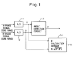
- FIG. 1 is a schematic block diagram showing a conventional amplitude calculation apparatus of an output signal of an encoder.
- 11 indicates an A/D converter converting from an analog to digital format the output of a detector (not shown) detecting the linear displacement, angle, angular speed, etc.
- an A-phase signal (sine wave)
- A-phase signal (sine wave)
- A/D converter converting from an analog to digital format a B-phase signal (sine wave) of the same member differing in phase from the A-phase signal by exactly 90° and outputting a digital value A
- 13 indicates an angle detection circuit detecting a phase difference ⁇ between the A-phase and B-phase based on the A-value and B-value
- 14 indicates an R calculation circuit calculating the resurge radius R.
- Past calculations include calculation of the squares and calculation of the square roots of the digital values A and B, so if calculated by hardware, the circuit size becomes larger and calculation by software ends up taking time.
- An object of the present invention is to reduce the circuit size of an apparatus calculating the resurge radius from the output of an encoder and shortening the processing time by software calculating the resurge radius.
- an amplitude calculation apparatus of an output signal of an encoder provided with a sampling means for sampling, at the same timing, an A-phase sine wave signal or a signal resembling the A-phase sine wave signal and a B-phase sine wave signal or a signal resembling the B-phase sine wave signal differing in phase by exactly a predetermined angle and thereby outputting an A/D converted value A of the A-phase sine wave signal or a signal resembling the A-phase sine wave signal and an A/D converted value B of the B-phase sine wave signal or a signal resembling the B-phase sine wave signal, an angle detection circuit for finding a phase angle ⁇ at different sampling points of a resurge waveform obtained by plotting the A/D converted value A of the A-phase sine wave signal or a signal resembling the A-phase sine wave signal and the A/D converted value B of the B-phase sine wave signal or a
- an amplitude calculation apparatus of an output signal of an encoder provided with a sampling means for sampling, at the same timing, an A-phase sine wave signal or a signal resembling the A-phase sine wave signal and a B-phase sine wave signal or a signal resembling the B-phase sine wave signal differing in phase by exactly a predetermined angle and thereby outputting an A/D converted value A of the A-phase sine wave signal or a signal resembling the A-phase sine wave signal and an A/D converted value B of the B-phase sine wave signal or a signal resembling the B-phase sine wave signal, an angle detection circuit for finding a phase angle ⁇ at different sampling points of a resurge waveform obtained by plotting the A/D converted value A of the A-phase sine wave signal or a signal resembling the A-phase sine wave signal and the A/D converted value B of the B-phase sine wave signal or a signal resembling
- an amplitude calculation program of an output signal of an encoder making a computer perform a step of sampling, at the same timing, an A-phase sine wave signal or a signal resembling the A-phase sine wave signal and a B-phase sine wave signal or a signal resembling the B-phase sine wave signal differing in phase by exactly a predetermined angle and thereby outputting an A/D converted value A of the A-phase sine wave signal or a signal resembling the A-phase sine wave signal and an A/D converted value B of the B-phase sine wave signal or a signal resembling the B-phase sine wave signal, a step of finding a phase angle ⁇ at different sampling points of a resurge waveform obtained by plotting the A/D converted value A of the A-phase sine wave signal or a signal resembling the A-phase sine wave signal and the A/D converted value B of the B-phase sine wave signal or a signal resembl
- an amplitude calculation program of an output signal of an encoder making a computer perform a step of sampling, at the same timing, an A-phase sine wave signal or a signal resembling the A-phase sine wave signal and a B-phase sine wave signal or a signal resembling the B-phase sine wave signal differing in phase by exactly a predetermined angle and thereby outputting an A/D converted value A of the A-phase sine wave signal or a signal resembling the A-phase sine wave signal and an A/D converted value B of the B-phase sine wave signal or a signal resembling the B-phase sine wave signal, a step of finding a phase angle ⁇ at different sampling points of a resurge waveform obtained by plotting the A/D converted value A of the A-phase sine wave signal or a signal resembling the A-phase sine wave signal and the A/D converted value B of the B-phase sine wave signal or a signal resembl
- calculation of the radius of the resurge waveform does not require calculation of the squares or calculation of the square roots, so when realizing this by hardware, the circuit size becomes smaller, while when realizing it by a program, the processing time is shortened.
- FIG. 2 is a schematic block diagram showing an amplitude calculation apparatus of an output signal of an encoder according to a first embodiment of the present invention.
- the A/D converters 21, 22 and angle detection circuit 23 are the same as the A/D converters 11, 12 and angle detection circuit 13 shown in FIG. 1.
- the R' calculation circuit 24 for calculating the radius R' of the resurge waveform is connected to the outputs of the A/D converters 21, 22 and angle detection circuit 23.
- the abscissa indicates the A-value
- the ordinate indicates the B-value.
- Both the A-value and B-value are in units of voltage, that is, volts.
- A-phase signal and the B-phase signal are complete sine waves and have a phase difference of 90°
- a true circular theoretical resurge waveform is obtained as illustrated, but when the waveform of one or more of the phases is not a complete sine wave but is a quasi sine wave or when the phase difference between the A-phase and B-phase is off from 90°, it is learned that the resurge waveform is not a true circle, but an ellipse.
- FIG. 4 is a table showing the relationship of the angle ⁇ of the resurge waveform and the coefficients ⁇ and ⁇ according to a first embodiment of the present invention.
- both the A-value and B-value are assumed to be digital signals expressed by 5 bits
- the 2 ⁇ angle is divided into 32 1/16 ⁇ areas
- the coefficients ⁇ and ⁇ are made predetermined 4-bit numbers for each angle area.
- the predetermined 4-bit numbers are set so as to make ⁇ A+ ⁇ B approximate the radius R of the theoretical resurge waveform shown in FIG. 3.
- the resurge radius R' is mainly determined by the A-value.
- the effect of the B-value is the smallest, so ⁇ is set to 2 0 and ⁇ is set to 2 -4 in advance.
- the effect of the A-value is slightly reduced and the effect of the B-value is slightly increased, so ⁇ is set to 2 -1 +2 -2 +2 -3 +2 -4 and ⁇ is set to 2 -2 +2 -3 .
- the coefficients ⁇ and ⁇ in each angle area are set as illustrated.
- the resurge radius R' is mainly determined by the B-value and the effect of the A-value is the smallest, so ⁇ is set to 2 -4 and ⁇ is set to 2° in advance. Further, at the final angle area of the fourth quadrant, 31 ⁇ /16 ⁇ 32 ⁇ /16, it is learned that the resurge radius R' is mainly determined by the A-value and the effect of the B-value is the smallest, so ⁇ is set to 2 0 and ⁇ is set to 2 -4 .
- ⁇ and ⁇ and ⁇ shown in FIG. 4 is only an example. In general, it is sufficient to set the coefficients ⁇ and ⁇ in advance by binary numbers of numbers of bits smaller than the number of bits of the A-value and B-value. By using the binary numbers, the processing at the digital calculation circuit, that is, the R' calculation circuit, becomes easy.
- the coefficients ⁇ and ⁇ are not limited to binary numbers. Any expression is possible if setting them so that ⁇ A+ ⁇ B approximates the radius R of the theoretical resurge waveform.
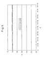
- FIG. 5 is a graph for explaining the effects obtained according to the above first embodiment.
- the resurge radius R' calculated by the first embodiment is not dependent on the angle ⁇ and remains at the substantially constant value of 1.0.
- FIG. 6 is a flow chart of a program for making a computer perform the operation of the first embodiment.
- the program samples, at the same timing, an A-phase sine wave signal or a signal resembling the A-phase sine wave signal and a B-phase sine wave signal or a signal resembling the B-phase sine wave signal differing in phase by exactly a predetermined angle and thereby acquires an A/D converted value A of the A-phase sine wave signal or a signal resembling the A-phase sine wave signal and an A/D converted value B of the B-phase sine wave signal or a signal resembling the B-phase sine wave signal.
- the program finds a phase angle ⁇ at different sampling points of a resurge waveform obtained by plotting the A/D converted value A of the A-phase sine wave signal or a signal resembling the A-phase sine wave signal and the A/D converted value B of the B-phase sine wave signal or a signal resembling the B-phase sine wave signal at the sampling points by the sampling on an X-axis and Y-axis.
- the program divides the resurge waveform into a predetermined number of angle areas and stores in advance the A-phase coefficient ⁇ and B-phase coefficient ⁇ corresponding to each of the divided angle areas, in which case, the coefficients being set so ⁇ A+ ⁇ B approximates a radius of a theoretical resurge waveform.
- the program calculates the radius R' of the resurge waveform as ⁇ A+ ⁇ B.
- the thus obtained radius R' expresses the amplitude of the detection signal of the encoder of the signal.
- FIGS. 7A to FIG. 7D are views explaining conversion of angles ⁇ of second to fourth quadrants of a resurge waveform to an angle ⁇ ' of a first quadrant according to the polarity of the A-value and B-value according to a second embodiment of the present invention.
- ⁇ and ⁇ corresponding to the thus obtained ⁇ ' are set in advance in the same way as the table of FIG. 4.
- the angles ⁇ ' are restricted to the first quadrant, in the example of FIG. 4, it is enough to use ⁇ and ⁇ corresponding to the angle area in the scope of the first quadrant from 0 ⁇ ' ⁇ /16 to 7 ⁇ /16 ⁇ ' ⁇ 8 ⁇ /16 and the circuit size can be made smaller than the case of the first embodiment.
- FIG. 8 is a flow chart of a program for making a computer perform the operation of the second embodiment.
- the program samples, at the same timing, an A-phase sine wave signal or a signal resembling the A-phase sine wave signal and a B-phase sine wave signal or a signal resembling the B-phase sine wave signal differing in phase by exactly a predetermined angle and thereby acquires an A/D converted value A of the A-phase sine wave signal or a signal resembling the A-phase sine wave signal and an A/D converted value B of the B-phase sine wave signal or a signal resembling the B-phase sine wave signal.
- the program finds a phase angle ⁇ at different sampling points of a resurge waveform obtained by plotting the A/D converted value A of the A-phase sine wave signal or a signal resembling the A-phase sine wave signal and the A/D converted value B of the B-phase sine wave signal or a signal resembling the B-phase sine wave signal at the sampling points by the sampling on an X-axis and Y-axis.
- the program finds a quadrant n of the phase angle ⁇ from the A/D converted value A and a polarity of the A/D converted value B, where, n - 1 / 2 ⁇ ⁇ ⁇ ⁇ ⁇ n / 2 ⁇ ⁇ , where n is 4 or a smaller natural number and converting the phase angle ⁇ of the quadrant n to a phase angle ⁇ ' of a quadrant 1.
- the program divides the resurge waveform into a predetermined number of angle areas in the quadrant 1 and presets and stores in advance an A-phase coefficient ⁇ and B-phase coefficient P in accordance with the divided angle areas.
- the coefficients are set so ⁇
- the program calculates the radius R' of the resurge waveform as ⁇
- the thus obtained radius R' expresses the amplitude of the detection signal of the encoder of the signal.
Landscapes
- Physics & Mathematics (AREA)
- General Physics & Mathematics (AREA)
- Transmission And Conversion Of Sensor Element Output (AREA)
- Digital Transmission Methods That Use Modulated Carrier Waves (AREA)
- Length Measuring Devices With Unspecified Measuring Means (AREA)
Applications Claiming Priority (1)
| Application Number | Priority Date | Filing Date | Title |
|---|---|---|---|
| JP2006171668A JP4119460B2 (ja) | 2006-06-21 | 2006-06-21 | エンコーダの出力信号の振幅算出装置及びエンコーダの出力信号の振幅算出プログラム |
Publications (3)
| Publication Number | Publication Date |
|---|---|
| EP1870677A2 true EP1870677A2 (fr) | 2007-12-26 |
| EP1870677A3 EP1870677A3 (fr) | 2017-03-22 |
| EP1870677B1 EP1870677B1 (fr) | 2018-07-18 |
Family
ID=38508731
Family Applications (1)
| Application Number | Title | Priority Date | Filing Date |
|---|---|---|---|
| EP07011383.2A Active EP1870677B1 (fr) | 2006-06-21 | 2007-06-11 | Appareil de calcul d'amplitude du signal de sortie d'un encodeur et programme de calcul d'amplitude du signal de sortie d'un encodeur |
Country Status (4)
| Country | Link |
|---|---|
| US (1) | US8402077B2 (fr) |
| EP (1) | EP1870677B1 (fr) |
| JP (1) | JP4119460B2 (fr) |
| CN (1) | CN100554978C (fr) |
Cited By (3)
| Publication number | Priority date | Publication date | Assignee | Title |
|---|---|---|---|---|
| EP2495534A1 (fr) * | 2011-03-01 | 2012-09-05 | Honeywell International, Inc. | Décodeur à angles à 360 degrés |
| US9041387B2 (en) | 2011-03-01 | 2015-05-26 | Perry A. Holman, Jr. | 360-degree angle sensor |
| US10809096B2 (en) | 2015-11-02 | 2020-10-20 | Honeywell International Inc. | Differential hall magnet polarity detection for AMR 360 degree sensor |
Families Citing this family (6)
| Publication number | Priority date | Publication date | Assignee | Title |
|---|---|---|---|---|
| JP5421669B2 (ja) * | 2009-06-23 | 2014-02-19 | アズビル株式会社 | 振幅算出装置および振幅算出方法 |
| JP5249158B2 (ja) * | 2009-08-27 | 2013-07-31 | 日本電産サンキョー株式会社 | エンコーダーのオフセット値補正方法 |
| JP2011257254A (ja) * | 2010-06-09 | 2011-12-22 | Hitachi Automotive Systems Ltd | 回転角検出装置 |
| JP6069653B2 (ja) * | 2011-01-27 | 2017-02-01 | 株式会社ミツトヨ | 光電式エンコーダ及びそのアライメント調整方法 |
| JP2014025871A (ja) * | 2012-07-30 | 2014-02-06 | Mitsutoyo Corp | エンコーダ出力信号補正装置 |
| KR102548249B1 (ko) * | 2017-05-15 | 2023-06-27 | 삼성전자주식회사 | 무선 수신기에서 타이밍 동기화를 갖는 캐리어 오프셋을 추정하는 방법 및 장치 |
Family Cites Families (24)
| Publication number | Priority date | Publication date | Assignee | Title |
|---|---|---|---|---|
| JPS5834865B2 (ja) | 1977-04-19 | 1983-07-29 | 日本航空電子工業株式会社 | ベクトル算出回路 |
| JPS54148350A (en) | 1978-04-21 | 1979-11-20 | Hitachi Denshi Ltd | Absolute value arithmetic circuit |
| US4599701A (en) * | 1983-10-19 | 1986-07-08 | Grumman Aerospace Corporation | Complex magnitude computation |
| JP2571096B2 (ja) * | 1988-04-18 | 1997-01-16 | ファナック株式会社 | エンコーダ |
| JPH09145756A (ja) * | 1995-11-21 | 1997-06-06 | Advantest Corp | 直交検波器の振幅誤差補正方法及び直交検波器 |
| US5970093A (en) * | 1996-01-23 | 1999-10-19 | Tiernan Communications, Inc. | Fractionally-spaced adaptively-equalized self-recovering digital receiver for amplitude-Phase modulated signals |
| JPH09325955A (ja) * | 1996-06-05 | 1997-12-16 | Sharp Corp | 二乗和の平方根演算回路 |
| DE19642199A1 (de) * | 1996-10-12 | 1998-04-16 | Heidenhain Gmbh Dr Johannes | Kontrollvorrichtung und Verfahren zur Prüfung von positionsabhängigen Abtastsignalen |
| US5987073A (en) * | 1997-03-27 | 1999-11-16 | Thomson Consumer Electronics, Inc. | Symbol timing recovery network for a carrierless amplitude phase (CAP) signal |
| US5949359A (en) * | 1997-05-09 | 1999-09-07 | Kollmorgen Corporation | Variable reluctance resolver to digital converter |
| US6553399B1 (en) * | 1998-03-27 | 2003-04-22 | Chung-Shan Institute Of Science | Method and circuit for envelope detection using a peel cone approximation |
| US6070181A (en) * | 1998-03-27 | 2000-05-30 | Chun-Shan Institute Of Science And Technology | Method and circuit for envelope detection using a peel cone approximation |
| TW480415B (en) * | 2000-05-17 | 2002-03-21 | Chung Shan Inst Of Science | Demodulation apparatus of square root and method of the same |
| ATE401244T1 (de) * | 2001-11-02 | 2008-08-15 | Gsi Group Corp | Codierer-selbstkalibrationsvorrichtung und - verfahren |
| US6556153B1 (en) * | 2002-01-09 | 2003-04-29 | Anorad Corporation | System and method for improving encoder resolution |
| US6879405B2 (en) * | 2002-11-18 | 2005-04-12 | Sony Precision Technology, Inc. | Displacement pickup |
| TWI239457B (en) * | 2004-04-12 | 2005-09-11 | Chung Shan Inst Of Science | Method and apparatus for demodulating square root |
| JP2005308547A (ja) | 2004-04-21 | 2005-11-04 | Mitsutoyo Corp | エンコーダ、その信号確認装置及び信号確認プログラム |
| JP2006003307A (ja) * | 2004-06-21 | 2006-01-05 | Mitsutoyo Corp | エンコーダ、及び、その信号調整方法 |
| JP4868319B2 (ja) * | 2004-07-29 | 2012-02-01 | エスティー‐エリクソン、ソシエテ、アノニム | 位相および/または振幅変調信号のための複合信号スケーリング |
| JP4713123B2 (ja) * | 2004-10-13 | 2011-06-29 | 株式会社ミツトヨ | エンコーダ出力信号補正装置 |
| JP4768248B2 (ja) * | 2004-10-13 | 2011-09-07 | 株式会社ミツトヨ | エンコーダ出力信号補正装置及び方法 |
| US7529320B2 (en) * | 2005-09-16 | 2009-05-05 | Agere Systems Inc. | Format efficient timing acquisition for magnetic recording read channels |
| US7852969B2 (en) * | 2007-07-30 | 2010-12-14 | Mitutoyo Corporation | System and method for dynamic calibration of a quadrature encoder |
-
2006
- 2006-06-21 JP JP2006171668A patent/JP4119460B2/ja active Active
-
2007
- 2007-06-11 US US11/760,968 patent/US8402077B2/en active Active
- 2007-06-11 EP EP07011383.2A patent/EP1870677B1/fr active Active
- 2007-06-11 CN CNB2007101091027A patent/CN100554978C/zh active Active
Cited By (4)
| Publication number | Priority date | Publication date | Assignee | Title |
|---|---|---|---|---|
| EP2495534A1 (fr) * | 2011-03-01 | 2012-09-05 | Honeywell International, Inc. | Décodeur à angles à 360 degrés |
| US8712722B2 (en) | 2011-03-01 | 2014-04-29 | Honeywell International, Inc. | 360-degree angle decoder |
| US9041387B2 (en) | 2011-03-01 | 2015-05-26 | Perry A. Holman, Jr. | 360-degree angle sensor |
| US10809096B2 (en) | 2015-11-02 | 2020-10-20 | Honeywell International Inc. | Differential hall magnet polarity detection for AMR 360 degree sensor |
Also Published As
| Publication number | Publication date |
|---|---|
| US8402077B2 (en) | 2013-03-19 |
| US20070297535A1 (en) | 2007-12-27 |
| CN101093234A (zh) | 2007-12-26 |
| JP4119460B2 (ja) | 2008-07-16 |
| CN100554978C (zh) | 2009-10-28 |
| EP1870677A3 (fr) | 2017-03-22 |
| JP2008002904A (ja) | 2008-01-10 |
| EP1870677B1 (fr) | 2018-07-18 |
Similar Documents
| Publication | Publication Date | Title |
|---|---|---|
| EP1870677A2 (fr) | Appareil de calcul d'amplitude du signal de sortie d'un encodeur et programme de calcul d'amplitude du signal de sortie d'un encodeur | |
| JP4142607B2 (ja) | バリアブルリラクタンスレゾルバ | |
| US5625310A (en) | Signal processing apparatus and displacement detecting apparatus using the same | |
| EP2078932A1 (fr) | Circuit de génération d'horloge, convertisseur d'angle analogique-numérique, et appareil de détection d'angle | |
| CN102564463A (zh) | 编码器、伺服单元及位置数据计算方法 | |
| CN112434254A (zh) | 针对正余弦编码器实现增量脉冲计数值校正处理的方法、系统、装置、处理器及其存储介质 | |
| EP2131156A1 (fr) | Appareil de détection de phase et appareil de détection de position | |
| CN1677868B (zh) | 用于量化装置的颤动系统 | |
| US5933106A (en) | Encoder signal analysis system for high-resolution position measurement | |
| US7099790B2 (en) | Sensor signal processor | |
| US6320524B1 (en) | R/D converter | |
| JP2013205366A (ja) | 位置検出器 | |
| EP4431879A1 (fr) | Démodulation intégrale d'un résolveur basée sur un temporisateur | |
| CN111800638A (zh) | 一种解码方法及解码装置 | |
| US5034745A (en) | Data acquisition with vernier control | |
| KR0155878B1 (ko) | 리니어 스텝핑 모터의 위치검출방법 및 그 장치 | |
| KR20090129594A (ko) | 정현파 엔코더의 출력신호를 이용한 회전자의 정밀위치검출방법 | |
| JP2010139405A (ja) | エンコーダ信号処理方法、エンコーダ装置及びサーボモータ | |
| JPS62142220A (ja) | デコ−ダを用いる内插回路 | |
| JP7281778B1 (ja) | 絶対位置エンコーダ | |
| JPH0552589A (ja) | 絶対値エンコーダ装置 | |
| JP2938472B2 (ja) | 回転角検出装置 | |
| RU2068620C1 (ru) | Преобразователь перемещения в код | |
| JPH1062203A (ja) | 位置検出装置 | |
| JPH0682269A (ja) | エンコーダ信号逓倍回路 |
Legal Events
| Date | Code | Title | Description |
|---|---|---|---|
| PUAI | Public reference made under article 153(3) epc to a published international application that has entered the european phase |
Free format text: ORIGINAL CODE: 0009012 |
|
| AK | Designated contracting states |
Kind code of ref document: A2 Designated state(s): AT BE BG CH CY CZ DE DK EE ES FI FR GB GR HU IE IS IT LI LT LU LV MC MT NL PL PT RO SE SI SK TR |
|
| AX | Request for extension of the european patent |
Extension state: AL BA HR MK YU |
|
| RAP1 | Party data changed (applicant data changed or rights of an application transferred) |
Owner name: FANUC CORPORATION |
|
| 17P | Request for examination filed |
Effective date: 20110314 |
|
| PUAL | Search report despatched |
Free format text: ORIGINAL CODE: 0009013 |
|
| AK | Designated contracting states |
Kind code of ref document: A3 Designated state(s): AT BE BG CH CY CZ DE DK EE ES FI FR GB GR HU IE IS IT LI LT LU LV MC MT NL PL PT RO SE SI SK TR |
|
| AX | Request for extension of the european patent |
Extension state: AL BA HR MK RS |
|
| RIC1 | Information provided on ipc code assigned before grant |
Ipc: G01D 1/16 20060101AFI20170216BHEP |
|
| AKX | Designation fees paid |
Designated state(s): DE |
|
| AXX | Extension fees paid |
Extension state: RS Extension state: MK Extension state: AL Extension state: HR Extension state: BA |
|
| GRAJ | Information related to disapproval of communication of intention to grant by the applicant or resumption of examination proceedings by the epo deleted |
Free format text: ORIGINAL CODE: EPIDOSDIGR1 |
|
| STAA | Information on the status of an ep patent application or granted ep patent |
Free format text: STATUS: GRANT OF PATENT IS INTENDED |
|
| GRAP | Despatch of communication of intention to grant a patent |
Free format text: ORIGINAL CODE: EPIDOSNIGR1 |
|
| INTG | Intention to grant announced |
Effective date: 20180109 |
|
| RIN1 | Information on inventor provided before grant (corrected) |
Inventor name: TANIGUCHI, MITSUYUKI Inventor name: MATSUO, TADAYOSHI Inventor name: KIKUCHI, HIROFUMI |
|
| GRAS | Grant fee paid |
Free format text: ORIGINAL CODE: EPIDOSNIGR3 |
|
| GRAJ | Information related to disapproval of communication of intention to grant by the applicant or resumption of examination proceedings by the epo deleted |
Free format text: ORIGINAL CODE: EPIDOSDIGR1 |
|
| GRAL | Information related to payment of fee for publishing/printing deleted |
Free format text: ORIGINAL CODE: EPIDOSDIGR3 |
|
| STAA | Information on the status of an ep patent application or granted ep patent |
Free format text: STATUS: REQUEST FOR EXAMINATION WAS MADE |
|
| GRAR | Information related to intention to grant a patent recorded |
Free format text: ORIGINAL CODE: EPIDOSNIGR71 |
|
| STAA | Information on the status of an ep patent application or granted ep patent |
Free format text: STATUS: GRANT OF PATENT IS INTENDED |
|
| GRAA | (expected) grant |
Free format text: ORIGINAL CODE: 0009210 |
|
| STAA | Information on the status of an ep patent application or granted ep patent |
Free format text: STATUS: THE PATENT HAS BEEN GRANTED |
|
| INTC | Intention to grant announced (deleted) | ||
| RIN1 | Information on inventor provided before grant (corrected) |
Inventor name: TANIGUCHI, MITSUYUKI Inventor name: KIKUCHI, HIROFUMI Inventor name: MATSUO, TADAYOSHI |
|
| AK | Designated contracting states |
Kind code of ref document: B1 Designated state(s): DE |
|
| INTG | Intention to grant announced |
Effective date: 20180608 |
|
| REG | Reference to a national code |
Ref country code: DE Ref legal event code: R096 Ref document number: 602007055393 Country of ref document: DE |
|
| REG | Reference to a national code |
Ref country code: DE Ref legal event code: R097 Ref document number: 602007055393 Country of ref document: DE |
|
| PLBE | No opposition filed within time limit |
Free format text: ORIGINAL CODE: 0009261 |
|
| STAA | Information on the status of an ep patent application or granted ep patent |
Free format text: STATUS: NO OPPOSITION FILED WITHIN TIME LIMIT |
|
| 26N | No opposition filed |
Effective date: 20190423 |
|
| PGFP | Annual fee paid to national office [announced via postgrant information from national office to epo] |
Ref country code: DE Payment date: 20250520 Year of fee payment: 19 |