EP1870865A1 - Alimentation de tension pour un avertisseur de risques - Google Patents
Alimentation de tension pour un avertisseur de risques Download PDFInfo
- Publication number
- EP1870865A1 EP1870865A1 EP06115833A EP06115833A EP1870865A1 EP 1870865 A1 EP1870865 A1 EP 1870865A1 EP 06115833 A EP06115833 A EP 06115833A EP 06115833 A EP06115833 A EP 06115833A EP 1870865 A1 EP1870865 A1 EP 1870865A1
- Authority
- EP
- European Patent Office
- Prior art keywords
- voltage
- switching arrangement
- diodes
- electrochemical
- sources
- Prior art date
- Legal status (The legal status is an assumption and is not a legal conclusion. Google has not performed a legal analysis and makes no representation as to the accuracy of the status listed.)
- Withdrawn
Links
Images
Classifications
-
- G—PHYSICS
- G08—SIGNALLING
- G08B—SIGNALLING SYSTEMS, e.g. PERSONAL CALLING SYSTEMS; ORDER TELEGRAPHS; ALARM SYSTEMS
- G08B29/00—Checking or monitoring of signalling or alarm systems; Prevention or correction of operating errors, e.g. preventing unauthorised operation
- G08B29/18—Prevention or correction of operating errors
- G08B29/181—Prevention or correction of operating errors due to failing power supply
-
- H—ELECTRICITY
- H02—GENERATION; CONVERSION OR DISTRIBUTION OF ELECTRIC POWER
- H02J—ELECTRIC POWER NETWORKS; CIRCUIT ARRANGEMENTS OR SYSTEMS FOR SUPPLYING OR DISTRIBUTING ELECTRIC POWER; SYSTEMS FOR STORING ELECTRIC ENERGY
- H02J7/00—Circuit arrangements for charging or discharging batteries or for supplying loads from batteries
- H02J7/50—Circuit arrangements for charging or discharging batteries or for supplying loads from batteries acting upon multiple batteries simultaneously or sequentially
Definitions
- the invention relates to a method for supplying power to a switch arrangement comprising electrochemical voltage sources comprising a hazard detector during an emergency operation of the switching arrangement.
- Wireless hazard alarms are hazard alarms that do not have a physical connection, such as a cable with a hazard control panel. The communication between the alarm control panel and the danger detector is done via the air interface.
- electrochemical voltage sources are often connected in series.
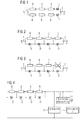
- Two strings of series-connected electrochemical voltage sources as shown in Figure 1, connected in parallel via diodes.
- the two strands each deliver about half of the required operating current for the hazard detector. If one strand fails, the other strand can maintain the required operating current because of the number of electrochemical voltage sources. So if, for example, an operating voltage of 2.2 V is required and as discharge voltage of an electrochemical Voltage source 0.9 V is assumed, three electrochemical voltage sources must be connected in series in each strand. The discharge end voltage of the entire switching arrangement is thus 2.7 V.
- the forward voltage of the diodes may be 0.5 V, so that the permissible operating voltage for the danger detector is not exceeded.
- six electrochemical voltage sources and two diodes are required for the switching arrangement.
- the object of the present invention is to be seen to propose an economical and easy way, so that with as little electrochemical voltage sources, the operating voltage of a hazard alarm is maintained during an emergency operation.
- a core of the invention is to be seen in that a diode is connected in parallel to a switching arrangement for powering the hazard alarm to each series-connected electrochemical voltage source, wherein the number of chemical voltage sources to be used (B) is selected such that in case of failure a voltage source (B), the operating voltage required for the hazard detector plus the forward voltage of one of the reverse-connected in parallel diodes (D) can be generated.
- B the number of chemical voltage sources to be used
- the number of chemical voltage sources to be used for the switching arrangement corresponds to the number of voltage sources required to reach the required operating voltage plus the forward voltage of one of the diodes connected in parallel in the reverse direction, plus at least one further voltage source.
- the chemical voltage sources can again rechargeable batteries, primary cells, etc. are used.
- the chemical voltage sources ideally have the same voltage and are therefore the same size.
- the diodes used are preferably diodes with a low forward voltage. Such diodes may be Schottky diodes, for example.
- switching arrangements consisting of series-connected electrochemical voltage sources and reverse-connected diodes are known, these known arrangements having the purpose of using the minimum required number of voltage sources.
- the supply voltage falls short of the required value if one of the electrochemical voltage sources or their connections fails, which is not the case with the inventive switching arrangement.
- Such a known switching arrangement is, for example, in a product brochure from Sonnenschein Lithium (Sonnenschein Lithium Batteries, Technical Brochure, page 22, 7. Circuit examples and instructions for use, Elektro.tec GmbH, Berlin http://www.lithium-batterie.de) contain.
- the switching arrangement shown there is used for over-discharge protection, for protection against charging and for protection against a short circuit of the switching arrangement.
- the inventive switching arrangement can be used in an emergency operation of the switching arrangement, that is, when an electrochemical voltage source or their connection has failed, also for at least partially feeding a consisting of modules hazard detector by one or more modules, the subordinate role to ensure the functionality play, not be energized.
- An advantage of this invention is that significantly less electrochemical Voltage sources are necessary and thus the number of redundant power sources can be reduced.
- FIG. 1 shows a known switching arrangement for the power supply of a device.
- Two strings of series-connected electrochemical voltage sources B will be connected in parallel via two diodes D. Normally, the two strands each deliver about half of the required operating current for the hazard detector. If one strand fails, due to the number of electrochemical voltage sources B, the other strand can maintain the required operating current.
- FIG. 2 shows a circuit arrangement according to the invention.
- the same number of electrochemical voltage sources B as in a strand according to FIG. 1 plus a further voltage source B are used, which are connected in series.
- a diode is connected in parallel in the reverse direction.
- more or fewer such voltage source diode pairs may be connected in series.
- FIG. 3 shows a circuit arrangement according to the invention which has a defective electrochemical voltage source.
- the inventive arrangement the function of the danger detector is guaranteed, since the remaining available voltage is still greater than the required operating voltage.
- FIG. 4 shows a circuit arrangement according to the invention connected to the power supply of the assemblies of a danger detector.
- Such assemblies are consumers, such as a communication unit, a detection unit, a second detection unit, an alarm signaling unit, etc.
- the arrangement of the electrochemical voltage sources and diodes corresponds to FIG. 2.
- a first load 11 Connected to the switching arrangement is a first load 11, which is as always and in particular also then should be operated when a single voltage source or the connection to it fails.
- a second consumer 14 is connected, which is only operated when all power sources and their connections are in perfect condition. Therefore, there is a voltage monitor 12 or other suitable device that allows to detect whether the switching device is in emergency mode, that is, whether a voltage source has failed and thereby a voltage drop can be registered.
- the switch 13 is closed or put into service with another suitable measure of the consumer 14. It is particularly advantageous that in this case, only the first consumer 11 must be designed so that it works with the reduced voltage in the event of a fault.
- the second consumer 14, however, can be designed so that it would fail with the voltage present in the event of a fault and only works properly when the normal operating voltage is applied.
Landscapes
- Engineering & Computer Science (AREA)
- Computer Security & Cryptography (AREA)
- Physics & Mathematics (AREA)
- General Physics & Mathematics (AREA)
- Stand-By Power Supply Arrangements (AREA)
Priority Applications (1)
| Application Number | Priority Date | Filing Date | Title |
|---|---|---|---|
| EP06115833A EP1870865A1 (fr) | 2006-06-21 | 2006-06-21 | Alimentation de tension pour un avertisseur de risques |
Applications Claiming Priority (1)
| Application Number | Priority Date | Filing Date | Title |
|---|---|---|---|
| EP06115833A EP1870865A1 (fr) | 2006-06-21 | 2006-06-21 | Alimentation de tension pour un avertisseur de risques |
Publications (1)
| Publication Number | Publication Date |
|---|---|
| EP1870865A1 true EP1870865A1 (fr) | 2007-12-26 |
Family
ID=37440645
Family Applications (1)
| Application Number | Title | Priority Date | Filing Date |
|---|---|---|---|
| EP06115833A Withdrawn EP1870865A1 (fr) | 2006-06-21 | 2006-06-21 | Alimentation de tension pour un avertisseur de risques |
Country Status (1)
| Country | Link |
|---|---|
| EP (1) | EP1870865A1 (fr) |
Citations (2)
| Publication number | Priority date | Publication date | Assignee | Title |
|---|---|---|---|---|
| GB2263593A (en) * | 1992-01-27 | 1993-07-28 | Samsung Electronics Co Ltd | Function control of battery-operated system; mobile alarm system |
| GB2312311A (en) * | 1996-04-15 | 1997-10-22 | E I Tech Ltd | An alarm device having a long-life power supply |
-
2006
- 2006-06-21 EP EP06115833A patent/EP1870865A1/fr not_active Withdrawn
Patent Citations (2)
| Publication number | Priority date | Publication date | Assignee | Title |
|---|---|---|---|---|
| GB2263593A (en) * | 1992-01-27 | 1993-07-28 | Samsung Electronics Co Ltd | Function control of battery-operated system; mobile alarm system |
| GB2312311A (en) * | 1996-04-15 | 1997-10-22 | E I Tech Ltd | An alarm device having a long-life power supply |
Similar Documents
| Publication | Publication Date | Title |
|---|---|---|
| DE102019201068B4 (de) | Stromversorgungssystem | |
| DE102012101516A1 (de) | Sicherheitsschaltvorrichtung mit Netzteil | |
| EP2920059B1 (fr) | Bateau avec système haute tension | |
| EP2203912B1 (fr) | Dispositif de séparation équipé d'un collecteur d'énergie pour une ligne électrique acheminant de l'énergie | |
| EP2585841A1 (fr) | Dispositif et procédé de surveillance d'une installation photovoltaïque | |
| DE10236165B4 (de) | Verfahren und Vorrichtung zum Symmetrieren der Kondensatoren einer Kondensatorbatterie | |
| EP3197726B1 (fr) | Réseau de bord | |
| EP3337008A2 (fr) | Alimentation en énergie pour un installation de porte et installation de porte correspondante | |
| EP2916414A1 (fr) | Module de surveillance destiné à la surveillance de conducteur de mise à la terre | |
| DE102008048701B4 (de) | Verfahren zum Betrieb einer Reihenschaltung von mindestens zwei LED's | |
| DE102012212374A1 (de) | Batteriesystem mit unterteilbarem Batteriestrang | |
| DE102011053728A9 (de) | Batteriesystem und Verfahren zum Abschalten von in Serie geschalteten Energiespeichermodulen einer Batterie eines Batteriesystems | |
| EP1870865A1 (fr) | Alimentation de tension pour un avertisseur de risques | |
| WO2004006404A2 (fr) | Montage pour surveiller les courants dans une pluralite de branches de courant d'un reseau | |
| DE102022116489A1 (de) | Vorrichtung zur Überwachung einer Stromversorgung | |
| DE102018203763A1 (de) | Vorrichtung und Verfahren zur unterbrechungsfreien Stromversorgung | |
| DE102018200173A1 (de) | Batteriesystem für ein Elektrofahrzeug, Verfahren zum Betrieb eines Batteriesystems und Elektrofahrzeug | |
| WO2009065665A2 (fr) | Distributeur pour un réseau électrique de bord avec une batterie métal-air | |
| EP3907110A1 (fr) | Système de tension embarqué pour un véhicule et procédé de fonctionnement d'un tel système de tension embarqué | |
| DE112016007222T5 (de) | Überwachungssystem | |
| BE1030672B1 (de) | Vorrichtung zur Überwachung einer Stromversorgung | |
| DE102018113489B4 (de) | Einheit | |
| DE10133289B4 (de) | Teilnehmerleitungsanschlusseinheit und Verfahren zur Fehlererkennung in der Stromversorgung | |
| EP1995843A2 (fr) | Dispositif de stockage d'énergie pour véhicules automobiles | |
| DE2822959C2 (de) | Verfahren zur Überprüfung der Sperr- und Durchlaßfähigkeit von redundant arbeitenden Dioden und Prüfschaltung zur Durchführung des Verfahrens |
Legal Events
| Date | Code | Title | Description |
|---|---|---|---|
| PUAI | Public reference made under article 153(3) epc to a published international application that has entered the european phase |
Free format text: ORIGINAL CODE: 0009012 |
|
| AK | Designated contracting states |
Kind code of ref document: A1 Designated state(s): AT BE BG CH CY CZ DE DK EE ES FI FR GB GR HU IE IS IT LI LT LU LV MC NL PL PT RO SE SI SK TR |
|
| AX | Request for extension of the european patent |
Extension state: AL BA HR MK YU |
|
| AKX | Designation fees paid | ||
| STAA | Information on the status of an ep patent application or granted ep patent |
Free format text: STATUS: THE APPLICATION IS DEEMED TO BE WITHDRAWN |
|
| 18D | Application deemed to be withdrawn |
Effective date: 20080627 |
|
| REG | Reference to a national code |
Ref country code: DE Ref legal event code: 8566 |