EP1871647B1 - Approche-ceinture de securite pour un vehicule automobile - Google Patents
Approche-ceinture de securite pour un vehicule automobile Download PDFInfo
- Publication number
- EP1871647B1 EP1871647B1 EP06722758A EP06722758A EP1871647B1 EP 1871647 B1 EP1871647 B1 EP 1871647B1 EP 06722758 A EP06722758 A EP 06722758A EP 06722758 A EP06722758 A EP 06722758A EP 1871647 B1 EP1871647 B1 EP 1871647B1
- Authority
- EP
- European Patent Office
- Prior art keywords
- pivoting
- seat
- belt
- guide means
- locking
- Prior art date
- Legal status (The legal status is an assumption and is not a legal conclusion. Google has not performed a legal analysis and makes no representation as to the accuracy of the status listed.)
- Ceased
Links
- 230000033001 locomotion Effects 0.000 claims description 20
- 238000006073 displacement reaction Methods 0.000 claims description 17
- 230000006835 compression Effects 0.000 claims description 16
- 238000007906 compression Methods 0.000 claims description 16
- 230000000694 effects Effects 0.000 claims description 2
- 238000009434 installation Methods 0.000 claims 3
- 230000008878 coupling Effects 0.000 description 4
- 238000010168 coupling process Methods 0.000 description 4
- 238000005859 coupling reaction Methods 0.000 description 4
- 238000005452 bending Methods 0.000 description 2
- 238000012840 feeding operation Methods 0.000 description 2
- 238000000034 method Methods 0.000 description 2
- 230000005540 biological transmission Effects 0.000 description 1
- 230000007423 decrease Effects 0.000 description 1
- 238000007493 shaping process Methods 0.000 description 1
- 230000000007 visual effect Effects 0.000 description 1
Images


Classifications
-
- B—PERFORMING OPERATIONS; TRANSPORTING
- B60—VEHICLES IN GENERAL
- B60R—VEHICLES, VEHICLE FITTINGS, OR VEHICLE PARTS, NOT OTHERWISE PROVIDED FOR
- B60R22/00—Safety belts or body harnesses in vehicles
- B60R22/02—Semi-passive restraint systems, e.g. systems applied or removed automatically but not both ; Manual restraint systems
- B60R22/03—Means for presenting the belt or part thereof to the wearer, e.g. foot-operated
Definitions
- the invention relates to a Gurtbringer for a motor vehicle according to the preamble of claim 1.
- a Gurtbringer is eg from the GB 2 235 361 A1 known.
- Belt feeders for motor vehicles which have a guide means and a belt catching device arranged on the guide means for feeding a safety belt.
- the Gurtfang worn moves out of a rest position in the inner lining of the motor vehicle, takes a seat belt and moves it to a bidding position in which a person sitting on a motor vehicle seat person can easily grasp the seat belt.
- the Gurtfang worn includes a pivoting device which pivots a pivoting member during the feeding of the Gurtbringers from a rest position in a transverse to the movement path, spread position and engages the seat belt with the pivoting element in a spread position and moves him to the offer position.
- the pivot member is in its rest position before the start of the supply to the guide rod, is pivoted during the supply in the direction of movement until a spread position is reached across the Bewebungsbahn, and thus engages with a curved catch surface the seat belt and guides him to the user.
- a locking device is required.
- Object of the present invention is to provide a Gurtbringer of the type described above, which has a pivoting device for a pivoting element with a simple and secure locking device that allows a return of the Gurtbringers in manual emergency operation without mechanical damage to the Gurtbringers.
- the solution according to the invention provides a belt feeder which reliably feeds a safety belt and, in an emergency, can be pushed manually into the interior trim of the motor vehicle without damaging the belt feeder.
- the pivoting means pivots the pivot member in the direction of movement in a direction transverse to the direction of movement, spread position and locked it in this position by means of the locking device.
- the locking device is at the same time designed for a possible emergency operation so that the pivoting element can be pivoted in the locked state by manual effort.
- the lock is automatically released, regardless of whether the return is done manually in normal operation via a drive or in emergency mode.
- the pivoting device is designed so that the pivoting of the pivoting element on the one hand during feeding by the force exerted by the seat belt on the pivoting force is not possible, but on the other hand can take place when a force is exerted on the pivoting element, the one by the interpretation of the pivoting device adjustable factor is greater than the force of the seat belt. As a result, a safety precaution for emergency operation is provided, which prevents the breakage of the pivoting element.
- the pivoting device and the locking device are preferably controlled by the feed movement of the guide means. This can be done by mechanical elements, in particular displaceable elements and spring elements, which cooperate with the guide means and are displaced relative to the guide means during the supply and return. But it is also conceivable that one or more separate, in particular electric drives are used to operate the pivoting device.
- the pivoting device has a control which cooperates with a locking element, a stop element, the pivoting element, a gear and the guide means so that the pivoting element is pivoted and locked in its spread position by the feed movement.
- the control is connected via a coupling region and a gear with the pivot member is moved by the supply and the associated movement of the guide means relative to the guide means and thus controls the pivoting of the pivot member in the spread position.
- the control in turn is connected to the locking element which, together with the stop element, locks the pivoting element in the spread position.
- the pivoting element can pivot in manually from its spread position when a force is exerted on the pivoting element, which exceeds the force of the seat belt on the pivoting element.
- the pivoting means may comprise mechanical springs and additional displaceable elements acting on the control element, the locking element and the stop member is operative to pivot the pivot member in the feed motion and to hold it in the spread position.
- the pivoting of the pivoting element can be controlled during the feeding with the spring elements, so that the pivoting preferably begins only after the pivoting element has emerged from the inner lining. In this way it is ensured that the pivoting element does not touch and damage the inner lining during pivoting and is not itself damaged by the inner lining.
- such a pivoting device includes a slider and three spring elements.
- the control element and the stop element are slidably connected to the sliding relative to the motor vehicle body guide means, while the third spring element slidably coupled to the slider with the vehicle body.
- the locking element is connected via an axis of rotation with the control element and is pivoted to lock the pivoting element in the spread position about the axis of rotation so that it is blocked by the spring held in position stopper element relative to the guide means in the feed direction.
- the locking element occurs during the return of the guide means in a frictional connection with the slider and is thereby pivoted from the locking position to its original position.
- the pivoting of the locking element is effected by the angular position of the locking element in the locking position relative to the slider and can be supported by suitable shaping of the slider and the locking element in the region of their points of contact.
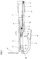
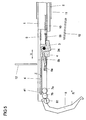
- Fig. 1 shows a side view of a Gurtbringers comprising a guide rod 1 formed as a guide means with a Gurtfang noticed arranged thereon.
- the guide rod 1 of the Gurtbringers is surrounded by a housing-like mounting device 11, with which the Gurtbringer is attached to a motor vehicle body and to which a motor and a transmission device connected to the motor are arranged, which serve as a drive for supplying or returning the guide rod 1.
- the guide rod 1 moves through an opening in the inner lining 12, engages with the Gurtfang Hughes the seat belt and leads it to a bidding position in which a person sitting on a motor vehicle seat person can easily grasp the seat belt to buckle.
- the Gurtfang shark has a pivoting device with a pivoting element 6, which is pivoted during the supply in the direction of movement in a direction transverse to the movement path, spread position and engages the seat belt.
- Fig. 1 the belt feeder is shown in a rest position before the beginning of the supply, in which the guide rod 1 is retracted into the inner lining 12 and is covered by the inner lining 12. From the motor vehicle interior, only the pivoting element 6, which substantially closes the opening in the inner lining 12, is visible from the belt feeder in this state. In this case, a particularly advantageous visual appearance is achieved when the vehicle interior facing surface contour of the pivot element 6 of the shape of the inner lining 12 adapts.
- the pivoting of the pivoting element 6 during the supply and return takes place by a pivoting device which is designed so that both the pivoting of the pivoting element 6 in the spread position and the pivoting are controlled by the supply and return movement of the guide rod 1.
- the pivoting device comprises a locking device, by means of which the pivoting element 6 is locked in the spread position, so that a pivoting of the pivoting element 6 by the force of the seat belt is not possible. The operation of the pivoting device and the locking device will be explained in more detail below.
- Fig. 1 to 7 show schematically the Gurtbringer in different positions before and during the supply and return.
- Fig. 1 first shows the belt feeder in the rest position before the beginning of the feed.
- the pivoting device is formed by displaceable elements and mechanical springs and has a slider 2, a locking element 3, a control element 4 and a stop element 5a, 5b, which are arranged substantially parallel to the guide rod.
- the slider 2 is connected via a first spring element 8 in the form of a compression spring with the mounting device 11 and can be moved along the displacement axis V substantially parallel to the guide rod 1.
- the displacement of the slider 2 may be limited in both directions along the displacement axis V with mechanical stops.
- the control element 4 and the stop element 5a, 5b are connected via two further spring elements 9, 10, designed as tension springs, connected to the guide rod 1 and can be moved parallel to the guide rod 1.
- the locking element 3 is connected via a rotation axis 34 with the control element 4 such that it is pivotable about the rotation axis 34. In the rest position, the locking element 3 extends substantially parallel to the axis of displacement V and is in one of the ends of the slide 2 in non-positive connection. In addition, the locking element 3 by a in Fig. 1 Torsion or bending spring not shown biased counterclockwise relative to the control 4.
- the control element 4 comprises a coupling region in the form of a first toothed segment section 41, which extends along the displacement axis V on a rectilinear section of the control element 4.
- This toothed segment section 41 engages in a gear formed from two toothed pinions 7a, 7b, which in turn engages in a coupling section of the pivoting element 6 in the form of a second toothed segment section 61.
- the pinion gears 7a, 7b and the pivoting element 6 are rotatably supported via a respective axis of rotation fixed relative to the guide rod 1.
- radially spaced circular portion extends the second sector gear portion 61 which engages in the second pinion gear 7 b.
- the spring forces of the compression spring 8 and the tension spring 9 act against each other.
- the spring constants of the compression spring 8 and the tension spring 9 are designed such that in the rest position the force exerted on the slider 2, the locking element 3 and the control element 4 spring force of the compression spring 8 exceeds the oppositely acting spring force of the tension spring 9.
- the slider 2 presses the control element 4 along the displacement axis V into a rest position, in which the control element 4 is deflected in the feed direction Z relative to the guide rod 1 to a maximum and holds the pivoting element in the pivoted state via the pinion gears 7a, 7b.
- the rest position of the control element 4 can be defined by a mechanical stop, which limits the deflection of the control element 4 and consequently also the elongation of the second tension spring 9. In this rest position of the control 4 grab the Teeth of the toothed pinion 7a in the tension spring 9 facing the starting region of the linear toothed segment portion 41 a.
- the locking element 3 extends in the rest position substantially parallel to the axis of displacement V of the control element 4 and rests on the stop element 5a, 5b.
- the stop element is constructed in two parts from a stop 5a and a straight guide 5b, but which are connected to each other so that they form a unit.
- the tension spring 10 connected to the straight guide 5b of the stop element 5a, 5b is relaxed in the rest position.
- the displacement of the stop element 5a, 5b can be limited in both directions along the axis of displacement V by mechanical stops.
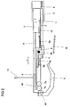
- Fig. 2 the belt feeder is shown at the beginning of the feeder.
- the slider 2 driven by the compressed compression spring 8, the guide rod 1 initially in the feed Z follow and thereby maintain the positive connection to the locking element 3 and thus also to the control 4.
- the force exerted by the compression spring 8 on the slide 2 force decreases continuously, but initially exceeds the force of the tension spring 9, thus keeping the control 4 relative to the guide rod 1 in position.
- the spring constants of the compression spring 8 and the tension spring 9 are designed so that a balance of the spring forces is achieved only after the guide rod 1 has leaked out with the hinged to the guide rod 1 pivot member 6 from the opening in the inner lining 12. This causes the pivoting of the pivoting element 6 begins only after reaching a pivotal position, namely, when the pivot member 6 can be pivoted freely through the inner lining 12.
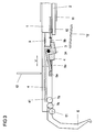
- the first pinion 7a engages in the remote from the tension spring 9 end portion of the sector gear portion 41 on the control element 4, as in Fig. 3 shown, and the pivoting of the pivoting element 6 is completed.
- the maximum deflection of the pivoting element 6 can be limited, for example, by a mechanical stop between the pivoting element 6 and the guide rod 1.
- the locking element 3 is no longer supported by the stop element 5a and rotated by the means of a torsion or bending spring bias against the control member 4 about the rotation axis 34 relative to the control 4, so that the pivot member 6 facing end of the locking element 3 seen in the feed direction Z comes to rest in front of the stop element 5a. Because the stop element 5a, 5b is held in position relative to the guide rod 1 by the spring force of the tension spring 10, the locking element 3 and thus also the control element 4 are blocked in the feed direction Z relative to the guide rod 1. The pivoting element 6 is locked in this way and can not be pivoted in the further supply by the force of the seat belt on the pivot member 6.
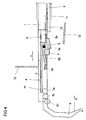
- Fig. 4 shows the belt feeder at the beginning of the manual return operation.
- force is first exerted on the pivot member 6 by a user. If this force is greater than the spring force of the stop element 5a, 5b holding in position tension spring 10, the pivot member 6 is pivoted in the return direction R and the control element 4 coupled to the pivot member 6 via the gear 7a, 7b relative to the guide rod 1 against the return direction R moved.
- the stop element 5a, 5b is deflected against the return direction R via the locking element 3 connected to the control element 4 and both the tension spring 9, which acts on the control element 4, and the tension spring 10, which is connected to the stop element 5a, 5b stretched.
- Fig. 5 shown.
- the pivoting element 6 can thus be pivoted manually in the locked state when the force on the pivoting element 6 is sufficiently large.
- the force required for pivoting is determined by the choice of the control element 4 and the stop element 5a, 5b holding spring elements 9, 10, the spring constants must be generally designed so that the pivoting is not effected by the force of the seat belt on the pivot member 6 , but only by a sufficiently larger manual force effect.
- Fig. 6 shows the pivot member 6 during the return in the fully pivoted state.
- the tension springs 9, 10 connected to the control element 4 and the stop element 5a, 5b are maximally stretched, and the stop element 5a, 5b is deflected at a maximum relative to the guide rod 1.
- the displacement paths of the control element 4 and of the stop element 5a, 5b can be limited by mechanical stops. It is also conceivable that the displacement of the stop element 5a, 5b in the return movement relative to the guide rod 1 is limited so that the pivot member 6 can not be fully pivoted initially, but this is possible only after unlocking.
- the guide rod 1 is pushed into the inner lining 12, and the compression spring 8 connected to the slide 2 is compressed. Once the spring force acting on the slider 2 compression spring 8 exceeds the force of the acting on the control element 4 tension spring 9, the pivot member 6 can not pivot, but is by the force of the compression spring 8 via the slide 2, the locking element 3 and the control. 4 kept in position. The return is completed as soon as the guide rod 1 is pushed completely into the inner lining 12 and thus the Gurtbringer is again in its rest position.
Landscapes
- Engineering & Computer Science (AREA)
- Mechanical Engineering (AREA)
- Automotive Seat Belt Assembly (AREA)
Claims (14)
- Mécanisme d'amenée de ceinture pour un véhicule automobile, comprenant :- un moyen preneur de ceinture pour faire avancer une ceinture de sécurité,- un moyen de guidage pour l'avance et le recul du moyen preneur de ceinture,- un élément pivotant qui est articulé par une extrémité sur le moyen de guidage avec possibilité de pivotement autour d'un axe de rotation et qui, dans une position de repos avant le commencement de l'avancement, est dirigé à l'opposé d'une composante de la direction d'avancement, et- un système de pivotement qui, conjointement avec l'élément pivotant, forme le moyen preneur de ceinture et qui fait pivoter l'élément pivotant pendant l'avancement à partir de la position de repos jusque dans une position en écartement qui s'étend transversalement à la trajectoire de déplacement,caractérisé en ce que
le système de pivotement (2-4, 5a, 5b, 6, 7a, 7b, 8-10) contient un dispositif de verrouillage (3, 5a, 5b) qui- verrouille pendant l'avancement l'élément de pivotement (6) dans sa position en écartement de telle façon qu'il ne pivote pas sous l'effet de la force de la ceinture de sécurité,- permet le pivotement de l'élément pivotant (6) par exercice d'une force manuelle lorsque le verrouillage est effectué, et- se déverrouille automatiquement lors du retrait du moyen de guidage (1). - Mécanisme d'amenée de ceinture selon la revendication 1, caractérisé en ce que le système de pivotement (2-4, 5a, 5b, 6, 7a, 7b, 8-10) est commandé par le mouvement du moyen de guidage (1).
- Mécanisme d'amenée de ceinture selon l'une des revendications 1 et 2, caractérisé en ce que le verrouillage de l'élément pivotant (6) est automatiquement annulé aussi bien lors du retour manuel que lors du retour par un entraînement.
- Mécanisme d'amenée de ceinture selon l'une des revendications précédentes, caractérisé en ce que le système de pivotement (2-4, 5a, 5b, 6, 7a, 7b, 8-10) contient des éléments (2-4, 5a, 5b) déplaçables en direction du moyen de guidage (1) et des ressorts mécaniques (8-10).
- Mécanisme d'amenée de ceinture selon la revendication 4, caractérisé en ce que le système de pivotement (2-4, 5a, 5b, 6, 7a, 7b, 8-10) comprend un élément de commande (4), un élément de verrouillage (3), un élément de butée (5a, 5b) et un mécanisme (7a, 7b), qui coopère avec le moyen de guidage (1) de telle façon que, par le mouvement d'avancement, l'élément pivotant (6) est pivoté jusque dans sa position en écartement et verrouillé.
- Mécanisme d'amenée de ceinture selon la revendication 5, caractérisé en ce que l'élément de verrouillage (3), l'élément de commande (4) et l'élément de butée (5a, 5b) sont réalisés sous forme d'éléments de tige, l'élément de verrouillage (3) et l'élément de commande (4) sont reliés l'un à l'autre via un axe de rotation (34), et l'élément de commande (4) et l'élément de butée (5a, 5b) sont montés sur le moyen de guidage (1) avec possibilité de déplacement le long de l'axe de déplacement (V).
- Mécanisme d'amenée de ceinture selon l'une des revendications 5 et 6, caractérisé en ce que le système de pivotement (2-4, 5a, 5b, 6, 7a, 7b, 8-10) comprend un coulisseau (2) et un premier, un second, et un troisième élément à ressort (8, 9, 10) qui coopèrent avec l'élément de commande (4), avec l'élément de verrouillage (3) et avec l'élément de butée (5a, 5b) pour faire pivoter et verrouiller l'élément pivotant (6).
- Mécanisme d'amenée de ceinture selon la revendication 7, caractérisé en ce que le pivotement de l'élément pivotant (6) par le système de pivotement (2-4, 5a, 5b, 6, 7a, 7b, 8-10) a lieu pendant l'avancement uniquement après la sortie de l'élément pivotant (6) hors de l'habillage intérieur (12).
- Mécanisme d'amenée de ceinture selon la revendication 8, caractérisé en ce que, dans la position en écartement de l'élément pivotant (6), l'élément de verrouillage (3) est bloqué par l'élément de butée (5a, 5b) en direction d'avancement (Z) par rapport au moyen de guidage (1).
- Mécanisme d'amenée de ceinture selon l'une des revendications 5 à 9, caractérisé en ce que le coulisseau (2) est couplé avec possibilité de déplacement via le premier élément à ressort (8) avec un système de montage (11) pour la fixation du mécanisme d'amenée de ceinture sur une carrosserie de véhicule automobile.
- Mécanisme d'amenée de ceinture selon l'une des revendications 5 à 10, caractérisé en ce que l'élément de commande (4) est couplé via le second élément à ressort (9) de façon déplaçable sur le moyen de guidage (1), lequel peut être déplacé par rapport au système de montage (11) pour l'avancement ou le recul du système preneur de ceinture.
- Mécanisme d'amenée de ceinture selon l'une des revendications 5 à 11, caractérisé en ce que l'élément de butée (5a, 5b) est couplé via le troisième élément à ressort (10) de façon déplaçable sur le moyen de guidage (1), lequel peut être déplacé par rapport au système de montage (11) pour l'avancement ou le recul du système preneur de ceinture.
- Mécanisme d'amenée de ceinture selon l'une des revendications 5 à 12, caractérisé en ce que le coulisseau (2) agit lors du retour du moyen de guidage (1) sur l'élément de verrouillage (3) de telle manière que le dispositif de verrouillage (3, 5a, 5b) est déverrouillé.
- Mécanisme d'amenée de ceinture selon l'une des revendications 5 à 13, caractérisé en ce que des ressorts de compression tout comme des ressorts de traction sont utilisables à titre d'éléments à ressort (8, 9, 10).
Applications Claiming Priority (2)
| Application Number | Priority Date | Filing Date | Title |
|---|---|---|---|
| DE102005017750A DE102005017750A1 (de) | 2005-04-12 | 2005-04-12 | Gurtbringer für ein Kraftfahrzeug |
| PCT/DE2006/000609 WO2006108383A1 (fr) | 2005-04-12 | 2006-04-03 | Approche-ceinture de securite pour un vehicule automobile |
Publications (2)
| Publication Number | Publication Date |
|---|---|
| EP1871647A1 EP1871647A1 (fr) | 2008-01-02 |
| EP1871647B1 true EP1871647B1 (fr) | 2009-04-01 |
Family
ID=36617183
Family Applications (1)
| Application Number | Title | Priority Date | Filing Date |
|---|---|---|---|
| EP06722758A Ceased EP1871647B1 (fr) | 2005-04-12 | 2006-04-03 | Approche-ceinture de securite pour un vehicule automobile |
Country Status (4)
| Country | Link |
|---|---|
| US (1) | US7686338B2 (fr) |
| EP (1) | EP1871647B1 (fr) |
| DE (2) | DE102005017750A1 (fr) |
| WO (1) | WO2006108383A1 (fr) |
Families Citing this family (9)
| Publication number | Priority date | Publication date | Assignee | Title |
|---|---|---|---|---|
| DE102006008930A1 (de) | 2006-02-23 | 2007-08-30 | Brose Fahrzeugteile Gmbh & Co. Kommanditgesellschaft, Coburg | Verfahren zur Steuerung eines Gurtbringers und Gurtbringer für ein Kraftfahrzeug |
| US8025339B2 (en) | 2008-09-16 | 2011-09-27 | Gm Global Technology Operations, Llc | Active material based seatbelt webbing presenter |
| US7967339B2 (en) * | 2009-01-13 | 2011-06-28 | GM Global Technology Operations LLC | Active material based safety belt buckle presenter |
| DE102009009906A1 (de) * | 2009-02-20 | 2010-08-26 | Trw Automotive Gmbh | Gurtschloss- oder Gurtbringer |
| GB2488137B (en) * | 2011-02-17 | 2015-10-07 | Bentley Motors Ltd | Mounting structure |
| DE102011112831A1 (de) * | 2011-09-12 | 2013-03-14 | Trw Automotive Gmbh | Gurtbringersystem |
| JP6243218B2 (ja) * | 2013-12-24 | 2017-12-06 | トヨタ自動車株式会社 | シートベルト装置 |
| US9358953B2 (en) | 2014-11-07 | 2016-06-07 | Ford Global Technologies, Llc | Seat belt presenter fault indication |
| US11180110B2 (en) * | 2018-09-12 | 2021-11-23 | Ford Global Technologies, Llc | Vehicle buckle assembly |
Family Cites Families (10)
| Publication number | Priority date | Publication date | Assignee | Title |
|---|---|---|---|---|
| DE3537089A1 (de) | 1985-10-18 | 1987-04-23 | Daimler Benz Ag | Sicherheitsgurtanordnung in einem fahrzeug |
| GB2235361B (en) * | 1989-08-30 | 1993-10-06 | Bsrd Ltd | Seat belt presenter |
| GB2235362B (en) * | 1989-08-30 | 1993-11-10 | Bsrd Ltd | Seat belt presenters |
| US5505461A (en) * | 1994-04-19 | 1996-04-09 | Caesars World, Inc. | Method for meeting IRS reporting requirements related to an electronic gaming machine |
| DE19901276B4 (de) * | 1999-01-15 | 2007-11-08 | Bayerische Motoren Werke Ag | Bringeinrichtung für den Sicherheitsgurt in einem Kraftfahrzeug |
| US6279954B1 (en) * | 1999-07-28 | 2001-08-28 | Joalto Design, Inc. | Restraint belt presenter having offset rotary action |
| WO2002009984A1 (fr) * | 2000-08-01 | 2002-02-07 | Takata Seat Belts, Inc. | Procede et dispositif de presentation d'une boucle de ceinture de securite |
| DE102004036189B4 (de) * | 2004-07-26 | 2006-06-08 | Autoliv Development Ab | Zum Fahrzeuginsassen abknickender Gurtbringer |
| JP2007030528A (ja) * | 2005-02-16 | 2007-02-08 | Takata Corp | タング取出し補助装置およびこれを用いたシートベルト装置 |
| DE102005029695A1 (de) * | 2005-06-24 | 2006-12-28 | Wilhelm Karmann Gmbh | Vorrichtung zum Verlangen eines Sicherheitsgurts eines Fahrzeugs in eine griffgünstige Position |
-
2005
- 2005-04-12 DE DE102005017750A patent/DE102005017750A1/de not_active Withdrawn
-
2006
- 2006-04-03 DE DE502006003325T patent/DE502006003325D1/de not_active Expired - Lifetime
- 2006-04-03 WO PCT/DE2006/000609 patent/WO2006108383A1/fr not_active Ceased
- 2006-04-03 EP EP06722758A patent/EP1871647B1/fr not_active Ceased
- 2006-04-03 US US11/918,463 patent/US7686338B2/en active Active
Also Published As
| Publication number | Publication date |
|---|---|
| US20090085339A1 (en) | 2009-04-02 |
| DE502006003325D1 (de) | 2009-05-14 |
| WO2006108383A1 (fr) | 2006-10-19 |
| US7686338B2 (en) | 2010-03-30 |
| EP1871647A1 (fr) | 2008-01-02 |
| DE102005017750A1 (de) | 2006-10-19 |
Similar Documents
| Publication | Publication Date | Title |
|---|---|---|
| EP2139361B1 (fr) | Entraînement de meuble à moteur électrique | |
| EP1418073B1 (fr) | Store à enrouler avec couvercle sur la fente extracte | |
| DE102012102838B4 (de) | Vorrichtung und Steuerungsverfahren zur Drehung einer Gurtführung eines Sicherheitsgurtes eines Fahrzeuges | |
| DE102018123949A1 (de) | Betätigungsvorrichtung | |
| DE102017205605A1 (de) | Kraft-Schwenktür-Betätigungsglied mit integriertem Tür-Kontrollmechanismus | |
| EP2729324A1 (fr) | Siège de véhicule à dossier rabattable pouvant être déplacé vers l'avant dans sa glissière longitudinale | |
| EP1307626B1 (fr) | Systeme de fermeture pour porte de vehicule | |
| DE3415930A1 (de) | Kraftfahrzeugfensterrollo | |
| DE19602916A1 (de) | Vorrichtung zum Verhindern einer Bewegungsumkehr und/oder des Herausziehens eines Gurtschlosses | |
| DE102007020000B4 (de) | Gurtaufroller | |
| DE102020113726A1 (de) | Türaufsteller mit Schubkette | |
| EP1871647B1 (fr) | Approche-ceinture de securite pour un vehicule automobile | |
| EP1989083B1 (fr) | Procédé pour commander un approche-ceinture et approche-ceinture pour véhicule à moteur | |
| DE202022107307U1 (de) | Türgriffanordnung für ein Fahrzeug | |
| DE3002500A1 (de) | Vorrichtung zur verstellung der lage eines versetzbaren elements bei einem fahrzeug, beispielsweise des fahrzeugsitzes | |
| DE102011000961A1 (de) | Schweißdrahtfördervorrichtung | |
| WO2006010484A1 (fr) | Element pour presenter une ceinture de securite a un passager de vehicule | |
| EP1853136B1 (fr) | Meuble reglable servant de siege | |
| DE3807928C2 (fr) | ||
| DE102004036361C5 (de) | Gurtbringer für ein Kraftfahrzeug | |
| DE102017105386B4 (de) | Gurtaufrollsystem mit Gurtaufroller und Kraftbegrenzer | |
| DE102015118992B4 (de) | Gurtschlossbringer mit verdrehbarer Umlenkungseinrichtung | |
| DE102011109562A1 (de) | Sicherheitsgurtvorrichtung für ein Fahrzeug und Fahrzeuge mit einer solchen Sicherheitsvorrichtung | |
| DE102021130595A1 (de) | Fahrzeugtürgriff mit Verstellung | |
| DE3007739A1 (de) | Passive sicherheitseinrichtung fuer fahrzeuge |
Legal Events
| Date | Code | Title | Description |
|---|---|---|---|
| PUAI | Public reference made under article 153(3) epc to a published international application that has entered the european phase |
Free format text: ORIGINAL CODE: 0009012 |
|
| 17P | Request for examination filed |
Effective date: 20071112 |
|
| AK | Designated contracting states |
Kind code of ref document: A1 Designated state(s): CZ DE FR |
|
| DAX | Request for extension of the european patent (deleted) | ||
| RBV | Designated contracting states (corrected) |
Designated state(s): CZ DE FR |
|
| GRAP | Despatch of communication of intention to grant a patent |
Free format text: ORIGINAL CODE: EPIDOSNIGR1 |
|
| GRAS | Grant fee paid |
Free format text: ORIGINAL CODE: EPIDOSNIGR3 |
|
| GRAA | (expected) grant |
Free format text: ORIGINAL CODE: 0009210 |
|
| AK | Designated contracting states |
Kind code of ref document: B1 Designated state(s): CZ DE FR |
|
| REF | Corresponds to: |
Ref document number: 502006003325 Country of ref document: DE Date of ref document: 20090514 Kind code of ref document: P |
|
| PLBE | No opposition filed within time limit |
Free format text: ORIGINAL CODE: 0009261 |
|
| STAA | Information on the status of an ep patent application or granted ep patent |
Free format text: STATUS: NO OPPOSITION FILED WITHIN TIME LIMIT |
|
| 26N | No opposition filed |
Effective date: 20100105 |
|
| REG | Reference to a national code |
Ref country code: FR Ref legal event code: PLFP Year of fee payment: 10 |
|
| REG | Reference to a national code |
Ref country code: FR Ref legal event code: PLFP Year of fee payment: 11 |
|
| REG | Reference to a national code |
Ref country code: FR Ref legal event code: PLFP Year of fee payment: 12 |
|
| REG | Reference to a national code |
Ref country code: FR Ref legal event code: PLFP Year of fee payment: 13 |
|
| PGFP | Annual fee paid to national office [announced via postgrant information from national office to epo] |
Ref country code: DE Payment date: 20190430 Year of fee payment: 14 |
|
| REG | Reference to a national code |
Ref country code: DE Ref legal event code: R081 Ref document number: 502006003325 Country of ref document: DE Owner name: BROSE FAHRZEUGTEILE SE & CO. KOMMANDITGESELLSC, DE Free format text: FORMER OWNER: BROSE FAHRZEUGTEILE GMBH & CO. KOMMANDITGESELLSCHAFT, COBURG, 96450 COBURG, DE |
|
| REG | Reference to a national code |
Ref country code: DE Ref legal event code: R119 Ref document number: 502006003325 Country of ref document: DE |
|
| PG25 | Lapsed in a contracting state [announced via postgrant information from national office to epo] |
Ref country code: DE Free format text: LAPSE BECAUSE OF NON-PAYMENT OF DUE FEES Effective date: 20201103 |
|
| PGFP | Annual fee paid to national office [announced via postgrant information from national office to epo] |
Ref country code: FR Payment date: 20210310 Year of fee payment: 16 Ref country code: CZ Payment date: 20210317 Year of fee payment: 16 |
|
| PG25 | Lapsed in a contracting state [announced via postgrant information from national office to epo] |
Ref country code: CZ Free format text: LAPSE BECAUSE OF NON-PAYMENT OF DUE FEES Effective date: 20220403 |
|
| PG25 | Lapsed in a contracting state [announced via postgrant information from national office to epo] |
Ref country code: FR Free format text: LAPSE BECAUSE OF NON-PAYMENT OF DUE FEES Effective date: 20220430 |