EP2139361B1 - Entraînement de meuble à moteur électrique - Google Patents
Entraînement de meuble à moteur électrique Download PDFInfo
- Publication number
- EP2139361B1 EP2139361B1 EP07856603.1A EP07856603A EP2139361B1 EP 2139361 B1 EP2139361 B1 EP 2139361B1 EP 07856603 A EP07856603 A EP 07856603A EP 2139361 B1 EP2139361 B1 EP 2139361B1
- Authority
- EP
- European Patent Office
- Prior art keywords
- furniture
- power transmission
- transmission element
- furniture drive
- drive
- Prior art date
- Legal status (The legal status is an assumption and is not a legal conclusion. Google has not performed a legal analysis and makes no representation as to the accuracy of the status listed.)
- Not-in-force
Links
Images


Classifications
-
- A—HUMAN NECESSITIES
- A47—FURNITURE; DOMESTIC ARTICLES OR APPLIANCES; COFFEE MILLS; SPICE MILLS; SUCTION CLEANERS IN GENERAL
- A47B—TABLES; DESKS; OFFICE FURNITURE; CABINETS; DRAWERS; GENERAL DETAILS OF FURNITURE
- A47B88/00—Drawers for tables, cabinets or like furniture; Guides for drawers
- A47B88/40—Sliding drawers; Slides or guides therefor
- A47B88/453—Actuated drawers
- A47B88/457—Actuated drawers operated by electrically-powered actuation means
-
- E—FIXED CONSTRUCTIONS
- E05—LOCKS; KEYS; WINDOW OR DOOR FITTINGS; SAFES
- E05Y—INDEXING SCHEME ASSOCIATED WITH SUBCLASSES E05D AND E05F, RELATING TO CONSTRUCTION ELEMENTS, ELECTRIC CONTROL, POWER SUPPLY, POWER SIGNAL OR TRANSMISSION, USER INTERFACES, MOUNTING OR COUPLING, DETAILS, ACCESSORIES, AUXILIARY OPERATIONS NOT OTHERWISE PROVIDED FOR, APPLICATION THEREOF
- E05Y2201/00—Constructional elements; Accessories therefor
- E05Y2201/60—Suspension or transmission members; Accessories therefor
- E05Y2201/622—Suspension or transmission members elements
- E05Y2201/71—Toothed gearing
- E05Y2201/722—Racks
-
- F—MECHANICAL ENGINEERING; LIGHTING; HEATING; WEAPONS; BLASTING
- F16—ENGINEERING ELEMENTS AND UNITS; GENERAL MEASURES FOR PRODUCING AND MAINTAINING EFFECTIVE FUNCTIONING OF MACHINES OR INSTALLATIONS; THERMAL INSULATION IN GENERAL
- F16C—SHAFTS; FLEXIBLE SHAFTS; ELEMENTS OR CRANKSHAFT MECHANISMS; ROTARY BODIES OTHER THAN GEARING ELEMENTS; BEARINGS
- F16C1/00—Flexible shafts; Mechanical means for transmitting movement in a flexible sheathing
- F16C1/10—Means for transmitting linear movement in a flexible sheathing, e.g. "Bowden-mechanisms"
- F16C1/12—Arrangements for transmitting movement to or from the flexible member
- F16C1/18—Arrangements for transmitting movement to or from the flexible member in which the end portion of the flexible member is laid along a curved surface of a pivoted member
-
- F—MECHANICAL ENGINEERING; LIGHTING; HEATING; WEAPONS; BLASTING
- F16—ENGINEERING ELEMENTS AND UNITS; GENERAL MEASURES FOR PRODUCING AND MAINTAINING EFFECTIVE FUNCTIONING OF MACHINES OR INSTALLATIONS; THERMAL INSULATION IN GENERAL
- F16C—SHAFTS; FLEXIBLE SHAFTS; ELEMENTS OR CRANKSHAFT MECHANISMS; ROTARY BODIES OTHER THAN GEARING ELEMENTS; BEARINGS
- F16C2314/00—Personal or domestic articles, e.g. household appliances such as washing machines, dryers
- F16C2314/70—Furniture
Definitions
- the invention relates to an electromotive furniture drive referred to in the preamble of claim 1 for adjusting parts of a furniture relative to each other, in particular a drawer relative to a body of a cabinet.
- Such furniture drives are well known, for example by DE 10 17 531 , or WO2006 / 029894 ,
- AT 413 631 B is an electromotive furniture drive for adjusting parts of a furniture relative to each other, in particular a drawer relative to a cabinet of a cabinet, known which has a drive unit, the output member is in the mounting position of the furniture drive with a part to be adjusted of the furniture in power transmission connection.
- the drive unit is designed as a rack and pinion gear having a standing with an electric motor of the drive unit in rotary drive connection gear which is in engagement with a rack which forms the output element of the furniture drive and is connected to a body of a drawer such that the Drawer relative to the body of the furniture according to the direction of rotation of the gear is retractable or retractable.
- a disadvantage of the known furniture drive is that it offers little freedom in terms of its arrangement on the body of the furniture, as the Rack is attached to the drawer and the gear must be in each adjustment position of the drawer in engagement with the rack.
- the invention has for its object to provide an electromotive furniture drive referred to in the preamble of claim 1 species, which does not have the disadvantages of the known furniture drive, ie in which the freedoms are increased with respect to the arrangement of the furniture drive to the furniture.
- the basic idea of the teaching according to the invention is to provide a flexible power transmission element for the production of a power transmission connection between the output element of the drive unit and the part of the furniture to be adjusted, which however can be claimed simultaneously for tension and compression.
- the drive unit of the furniture drive can be arranged at almost any point of the furniture, wherein the power transmission connection between the output element of the drive unit and the part to be adjusted of the furniture is made via the flexible force transmission element.
- the force transmission element can be claimed both train and on pressure, both adjusting movements can be performed by means of the furniture drive according to the invention, in which the force transmission element is subjected to pressure, such as an extension of a drawer, as well as adjusting movements, in which the power transmission element to train is claimed, for example, a retraction of a drawer.
- the furniture drive according to the invention is relatively simple and inexpensive to produce and robust.
- the furniture drive according to the invention is suitable for adjusting any parts of a piece of furniture, as far as the requisite adjusting forces can be transmitted from the power transmission element.
- the furniture drive according to the invention is particularly well suited for adjusting pull-outs, in particular drawers, relative to a carcass of a cabinet. Characterized in that the force transmission element is flexible and thus can be deflected, it is inventively possible, for example, to attach the housing of the furniture drive to a rear wall of a cabinet, while one of the drawer to be adjusted facing the end of the power transmission element is fixed to the drawer.
- the furniture drive according to the invention is relatively simple and inexpensive to produce and robust in construction.
- An advantageous development of the teaching according to the invention provides that a part of the furniture to be adjusted facing the first end of the power transmission element is fixed to the part to be adjusted of the furniture.
- the first end of the power transmission element can be fastened, for example, by means of a suitable fitting on the part of the furniture to be adjusted.
- a decoupling of the drawer of the drive unit instead, with the drawer moves after decoupling due to their inertia in the direction of the retracted position. Because the drawer is in the range of the end position This movement is decoupled from the drive unit, the risk is avoided that a body part of a user is trapped under the action of the driving force of the drive unit between the drawer and the body of the furniture.
- a second end of the force transmission element remote from the part of the furniture to be adjusted can be fixed to the output element.
- the output element can be designed as a rotatably drivable winding drum on which the force transmission element can be wound up and from which the force transmission element can be unwound.
- An advantageous development of the aforementioned embodiment provides that a lying between the pressure point and the second end of the power transmission element unloaded part of the power transmission element is receivable by a receiving device.
- the unloaded part of the power transmission element is accommodated in the receiving device in an orderly manner.
- the receiving device has a drum-like receptacle in which the second end of the power transmission element spirally is hineinbewegbar.
- the force transmission element sets in an adjusting movement, in which increases the distance of the second end of the force transmission element of the Anpreßstelle, a spiral in the drum-like receptacle.
- the output element of the furniture drive according to the invention can be, for example, a linearly movable output element along a linear movement axis.
- the output element is rotationally driven by an electric motor of the drive unit, as provided by an advantageous development of the teaching of the invention. In this way, a particularly simple construction of the furniture drive according to the invention.
- a development of the aforementioned embodiment provides that the drum-like receptacle is arranged offset in the axial direction to the axis of rotation of the output element. In this way, the furniture drive according to the invention is particularly space-saving and compact.
- the drum-like receptacle is in rotary drive connection with the output element, in particular rotationally fixed or substantially non-rotatably connected to the output element.
- the output element is not rotationally driven by an electric motor of the drive unit, but via power transmission element by hand. Due in particular essentially non-rotatable connection of the drum-like receptacle with the output element in this case, the receptacle rotates substantially synchronously with. In this way, the friction between the moving into the receiving container power transmission element and the inner wall is reduced.
- the power transmission element particularly easily into the receptacle, in a spiral manner in the form of adjacent to each other in the axial direction of the receptacle turns. If the axial extent of the receptacle is filled with a layer of adjacent turns, so the force transmission element lies over this layer in one or more further layers of axially adjacent turns arranged in the receptacle a.
- the force transmission element is designed as a rack which is in engagement with a gear which forms the output element of the drive unit or is in rotary drive connection with the output element of the drive unit.
- the rack which forms the power transmission element of the furniture drive, positively engages with a toothing of the toothed wheel, which forms the output element of the drive unit or is in rotary drive connection with the output element of the drive unit. In this way, a slip between the power transmission element and the output element is avoided.
- racks are available as relatively simple and inexpensive standard components and are suitable for transmitting considerable forces.
- the rack for example Made of plastic and be dimensioned so that on the one hand flexible, but on the other hand in the required manner to train and pressure claims.
- the force transmission element is accommodated in a sheath. In this embodiment, it is avoided that the force transmission element buckles laterally under compressive stress.
- the first and the second end of the power transmission element are arranged at an angle to each other.
- Such an angular arrangement of the ends of the power transmission element to each other according to the invention allows characterized in that the force transmission element is designed to be flexible.
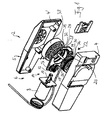
- FIG. 1 an embodiment of a furniture drive 2 according to the invention is shown, which in this embodiment for adjusting a in Fig. 1 not shown drawer of a Fig. 1 also not shown cabinet serves.
- the furniture drive 2 has a housing 5 formed by two half-shells 4, 4 'in which a drive unit 6 with an electric motor 8 is accommodated.
- the electric motor 8 has an output shaft 10, which is formed in this embodiment as a worm and is in engagement with a worm wheel 12 of a gear assembly 14.
- a first gear 16 is rotatably connected, which meshes with a second gear 18, which in turn meshes with a first toothing 20 of a third gear 22.
- the worm wheel 12 with the first gear 16, the second gear 18 and the third gear 22 are rotatably supported on a gear holder 24 which is held inside the housing 5.
- the furniture drive 2 has a flexible force transmission element that can be subjected to tension and compression, which in this exemplary embodiment is formed by a toothed rack 26.
- the rack 26 is in this embodiment to achieve the inventively provided flexibility of plastic and is dimensioned in its cross-section so that on the one hand the required flexibility is achieved, on the other hand, however, the required tensile and compressive forces can be transmitted without damaging the rack 26.
- the third gear 22 forms in this embodiment, the output element of the drive unit 6 and is provided with a first toothing 20 in the axial direction of the third gear 22 offset second toothing with which the rack 26 is engaged.
- a remote from the adjusting part of the furniture second end 32 of the rack 26 is movable relative to the third gear, so not fixed to this.
- pressing means are provided, which in this embodiment have a pressure roller 34 which press the rack 26 at a contact point 36 to the second toothing 30 of the third gear 22 and hold the rack 26 in force communication with the third gear 22.
- the second gear 18 is in engagement with the first toothing 20 and the rack 26 in engagement with the second toothing 30 of the third gear 22.
- the third gear 22 has a single toothing, with the Both the second gear 18 as also the rack 26 are engaged.
- a receiving device For receiving a lying between the pressure point 36 and the second end 32 of the rack 26 unloaded part of the rack 26, a receiving device is provided which has a drum-like receptacle 38 in this embodiment, in which the second end 32 of the rack 26 is hineinbewegbar spirally, such as this in Fig. 1 is indicated. How out Fig. 1 can be seen, the drum-like receptacle 38 is arranged offset in the axial direction of the axis of rotation of the third gear 22 to the same.
- the drum-like receptacle 38 is rotatably connected via an axis 39 with the third gear 22 so that it rotates synchronously with the third gear 22.
- an integrally formed on the gear holder 24 guide is provided.
- FIG. 2 in which a perspective view of the furniture drive according to Fig. 2 is shown in FIG Fig. 1 Sheath 40, not shown, for rack 26. Sheathing 40 is fixed in position and has a lower flexibility than rack 26, with rack 26 soily received in shroud 40 and slidably reciprocated relative to shroud 40 , Out Fig. 2 It can also be seen that the second gear 18 is in engagement with the first gear 20 and the rack 26 is in engagement with the second gear 30 of the third gear 22.
- Fig. 3 shows a further perspective view of the furniture drive 2, wherein it can be seen that the pressure roller 34 presses the rack 26 at the pressure point 36 against the second toothing 30 of the third gear 22 and so holds the rack 26 in power transmission connection with the third gear 22.
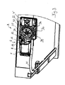
- Fig. 4 shows the furniture drive 2 in mounting position on a cabinet, for reasons of illustration, parts of the cabinet, in particular its rear wall, to which the housing 5 of the furniture drive 2 is attached, are not shown.
- the furniture drive 2 is used to adjust an in Fig. 4 also not shown drawer, which is connected via movable rails 42, 44 of telescopic rail assemblies extendable to the body of the cabinet.
- Fig. 4 can be seen, in this embodiment, the ends of the rack 40 received in the rack 26 are arranged at an angle to each other, in this embodiment namely at an angle of about 90 °.
- Fig. 5 shows a detail in the region of the connection of the rack 26 with the movable telescopic rail 24.
- the first end of the rack 26 via a fitting 46 is fixedly connected to the movable rail 42.
- the pin 48 is guided in an axial slot 50 of the casing in the adjustment direction, which corresponds to the axial direction of the casing 42.
- the drawer can also be manually moved from the extended position to the retracted position by a user einschiebt the drawer by hand.
- the rack 26 is subjected to pressure, where it is the third Gear 22 so wooan administrat that this in Fig. 1 moved counterclockwise.
- the second end 32 of the rack 26 moves into the drum-like receptacle 38 and abuts in the form of successive turns in the axial direction of the receptacle 38 to the cylindrical inner wall of the receptacle 38.
- the receptacle 38 Since the receptacle 38 is rotatably connected via the axis 39 with the third gear 22, in this case the friction between the second end 32 of the rack 26 and the inner wall of the receptacle 38 is substantially reduced. In this way, it is possible that the rack 38 arranged in the form of arranged in the axial direction of the receptacle 38 juxtaposed turns to the cylindrical inner wall of the receptacle 38. Characterized in that the rack 26 has certain elastic properties, it puts itself when moving into the receptacle 38 close to the inner wall.
- the rack 26 subsequently sets in a second layer of axially juxtaposed turns in the receptacle 38 a. If necessary, this process repeats to form additional layers until the drawer is in its retracted position again. It has surprisingly been found that the co-rotation of the receptacle 38 upon rotation of the third gear 22, the orderly recording of the rack 26 is substantially promoted in the receptacle 38.
- the furniture drive 2 according to the invention is relatively simple and inexpensive to produce and offers in terms of the arrangement of the furniture drive 2 at one Body of furniture greater liberties than known furniture drives. How out Fig. 4 it can be seen, the furniture drive in the illustrated embodiment is attached to a (not shown) rear wall of the cabinet, wherein the ends of the rack 26 are arranged at an angle to each other and in this embodiment form an angle of about 90 ° with each other.
Landscapes
- Drawers Of Furniture (AREA)
- Transmission Devices (AREA)
Claims (9)
- Entraînement de meuble électromoteur destiné au réglage de pièces d'un meuble l'une par rapport à l'autre, en particulier d'un tiroir par rapport à un corps d'une armoire,
comprenant au moins une unité d'entraînement dont l'unité de sortie, dans la position de montage de l'entraînement de meuble, est en liaison de transmission de mouvement avec une pièce du meuble devant être réglée,
étant entendu que l'unité de sortie est en liaison de transmission de mouvement avec la pièce du meuble devant être réglée par le biais d'au moins un élément de transmission de mouvement (26) flexible pouvant être sollicité en traction et en pression,
caractérisé
en ce que l'élément de transmission de mouvement (26) est réalisé comme crémaillère flexible, qui est en prise avec une roue dentée (22) qui constitue l'élément de sortie de l'unité d'entraînement ou en liaison d'entraînement par rotation avec l'élément de sortie de l'unité d'entraînement (6), et
en ce que l'élément de transmission de mouvement est logé dans une gaine (40). - Entraînement de meuble selon la revendication 1, caractérisé en ce qu'une première extrémité de l'élément de transmission de mouvement (26) dirigée vers la pièce du meuble devant être réglée est fixée sur la pièce du meuble devant être réglée.
- Entraînement de meuble selon la revendication 1 ou 2, caractérisé en ce qu'une deuxième extrémité (32) de l'élément de transmission de mouvement (26) dirigée à l'opposé de la pièce du meuble devant être réglée peut être déplacée par rapport à l'élément de sortie et en ce que l'élément de transmission de mouvement (26) est maintenu en liaison de transmission de mouvement avec l'élément de sortie à au moins un point de pression (36) par le biais de moyens de pression.
- Entraînement de meuble selon la revendication 3, caractérisé en ce qu'une pièce sans charge de l'élément de transmission de mouvement (26) située entre le point de pression (36) et la deuxième extrémité de l'élément de transmission de mouvement peut être reçue par un dispositif de réception.
- Entraînement de meuble selon la revendication 4, caractérisé en ce que le dispositif de réception présente un logement de réception similaire à un tambour (38), dans lequel la deuxième extrémité (32) de l'élément de transmission de mouvement peut être introduite dans une forme de spirale.
- Entraînement de meuble selon l'une des revendications précédentes, caractérisé en ce que l'élément de sortie peut être entraîné en rotation par un électromoteur (8) de l'unité d'entraînement (6).
- Entraînement de meuble selon la revendication 5 et 6, caractérisé en ce que le logement de réception similaire à un tambour (38) est agencé dans la direction axiale de l'axe de rotation de l'élément de sortie en position décalée par rapport à celui-ci.
- Entraînement de meuble selon la revendication 6 ou 7, caractérisé en ce que le logement de réception similaire à un tambour (38) est en liaison d'entraînement par rotation avec l'élément de sortie, étant en particulier relié de façon fixe ou sensiblement fixe en rotation avec l'élément de sortie.
- Entraînement de meuble selon l'une des revendications précédentes, caractérisé en ce que les première et deuxième extrémités (32) de l'élément de transmission de mouvement (26), dans la position de montage de l'entraînement de meuble (2), sont agencées dans un angle l'une par rapport à l'autre.
Applications Claiming Priority (2)
| Application Number | Priority Date | Filing Date | Title |
|---|---|---|---|
| DE200720004337 DE202007004337U1 (de) | 2007-03-21 | 2007-03-21 | Elektromotorischer Möbelantrieb |
| PCT/EP2007/010855 WO2008113401A1 (fr) | 2007-03-21 | 2007-12-12 | Entraînement de meuble à moteur électrique |
Publications (2)
| Publication Number | Publication Date |
|---|---|
| EP2139361A1 EP2139361A1 (fr) | 2010-01-06 |
| EP2139361B1 true EP2139361B1 (fr) | 2013-09-11 |
Family
ID=39205142
Family Applications (1)
| Application Number | Title | Priority Date | Filing Date |
|---|---|---|---|
| EP07856603.1A Not-in-force EP2139361B1 (fr) | 2007-03-21 | 2007-12-12 | Entraînement de meuble à moteur électrique |
Country Status (3)
| Country | Link |
|---|---|
| EP (1) | EP2139361B1 (fr) |
| DE (1) | DE202007004337U1 (fr) |
| WO (1) | WO2008113401A1 (fr) |
Families Citing this family (16)
| Publication number | Priority date | Publication date | Assignee | Title |
|---|---|---|---|---|
| DE102013013199B4 (de) | 2013-04-18 | 2017-11-16 | Deon Group AG | Elektromotorischer Möbelantrieb |
| DE202013007106U1 (de) | 2013-08-09 | 2014-11-13 | Deon Group AG | Möbelantrieb |
| DE102014115126A1 (de) | 2014-07-18 | 2016-01-21 | Deon Group AG | Elektromotorisch verstellbare Stützeinrichtung |
| DE102014115033A1 (de) | 2014-07-18 | 2016-01-21 | Deon Group AG | Elektromotorisch verstellbare Stützeinrichtung |
| DE102014115039A1 (de) | 2014-07-18 | 2016-01-21 | Deon Group AG | Ausrückungsverfahren zur Ausrückung eines Möbelantriebs |
| DE102014115084A1 (de) | 2014-10-16 | 2016-04-21 | Deon Group AG | Möbelantrieb |
| EP3009051B1 (fr) | 2014-10-16 | 2018-11-07 | De Werth Group AG | Dispositif d'appui réglable à moteur électrique |
| DE102014115125A1 (de) | 2014-10-17 | 2016-05-19 | Deon Group AG | Elektromotorische Verstellvorrichtung |
| DE102015106994A1 (de) | 2015-05-05 | 2016-11-10 | Deon Group AG | Elektromotorischer Möbelantrieb |
| AT18049U1 (de) * | 2020-01-22 | 2023-11-15 | Blum Gmbh Julius | Möbelantrieb zum Bewegen eines bewegbaren Möbelteiles |
| DE102021102440A1 (de) | 2020-02-05 | 2021-08-05 | De Werth Group Ag | Elektromotorische Verstellvorrichtung |
| DE102021108208A1 (de) | 2020-08-12 | 2022-02-17 | De Werth Group Ag | Elektromotorischer Möbelantrieb |
| DE102021119984A1 (de) | 2020-08-12 | 2022-02-17 | De Werth Group Ag | Elektromotorisch verstellbare Stützeinrichtung |
| DE202021101715U1 (de) | 2020-08-17 | 2021-11-23 | De Werth Group Ag | Elektromotorischer Möbelantrieb |
| DE102021105230A1 (de) | 2021-03-04 | 2022-09-08 | De Werth Group Ag | Seilzugbetätigbares Möbelscharnier |
| WO2025214602A1 (fr) | 2024-04-11 | 2025-10-16 | Pampero AG | Entraînement de meuble à moteur électrique |
Family Cites Families (5)
| Publication number | Priority date | Publication date | Assignee | Title |
|---|---|---|---|---|
| DE1017531B (de) | 1955-07-18 | 1957-10-10 | Fiege & Joest Elektromotoren W | Einrichtung zum Auffangen und Dosieren von nachlaufendem Gut |
| AT413631B (de) | 2001-12-27 | 2006-04-15 | Blum Gmbh Julius | Anordnung mit einem bewegbaren möbelteil, mit einer antriebseinheit und mit einer regeleinrichtung |
| AT500362B1 (de) * | 2002-06-27 | 2007-01-15 | Blum Gmbh Julius | Anordnung mit einem bewegbaren möbelteil und mit einer antriebseinheit |
| DE102004045567A1 (de) * | 2004-09-17 | 2006-04-06 | Küster Automotive Door Systems GmbH | Verstellvorrichtung zum Verstellen, insbesondere zum translatorischen Verschieben, eines Möbelteils |
| DE202006012283U1 (de) * | 2006-08-09 | 2007-12-13 | Grass Gmbh | Vorrichtung zum Bewegen eines ersten Möbelteils relativ zu einem zweiten Möbelteil und Möbel |
-
2007
- 2007-03-21 DE DE200720004337 patent/DE202007004337U1/de not_active Expired - Lifetime
- 2007-12-12 WO PCT/EP2007/010855 patent/WO2008113401A1/fr not_active Ceased
- 2007-12-12 EP EP07856603.1A patent/EP2139361B1/fr not_active Not-in-force
Also Published As
| Publication number | Publication date |
|---|---|
| EP2139361A1 (fr) | 2010-01-06 |
| DE202007004337U1 (de) | 2008-09-04 |
| WO2008113401A1 (fr) | 2008-09-25 |
Similar Documents
| Publication | Publication Date | Title |
|---|---|---|
| EP2139361B1 (fr) | Entraînement de meuble à moteur électrique | |
| EP1609647B1 (fr) | Store à enrouler avec couvercle sur la fente extracte | |
| EP2575548B1 (fr) | Dispositif d'escamotage pour escamoter une partie de meuble montée mobile | |
| EP2797461B1 (fr) | Dispositif de synchronisation pour tiroir | |
| EP2136680B1 (fr) | Système de couplage pour partie de meuble mobile | |
| DE102018123949A1 (de) | Betätigungsvorrichtung | |
| EP1905625A1 (fr) | Store doté d'un rail de guidage sans contre-dépouille | |
| WO2019011527A1 (fr) | Système de poignée de porte d'un véhicule automobile | |
| DE102016200649A1 (de) | Elektrisch längsverstellbare Lenksäule für ein Kraftfahrzeug | |
| EP2196115A1 (fr) | Entraînement pour un dispositif de chauffage du café et dispositif de chauffage du café | |
| AT505562B1 (de) | Möbelantrieb | |
| EP1817983A1 (fr) | Dispositif pour influencer le mouvement des parties de meuble l'une par rapport à l'autre et une glissière pour tiroirs, ainsi qu'un procédé de fabrication d'un tel dispositif | |
| DE102017123613A1 (de) | Einzugsvorrichtung und Verfahren zum Öffnen und Schließen eines bewegbaren Möbelteils | |
| EP3181013A1 (fr) | Système d'extracteur pour une partie de meuble mobile | |
| EP3132712A1 (fr) | Dispositif de deplacement d'un element de meuble mobile dans un sens d'ouverture par rapport a un corps d'un meuble | |
| DE102015216715A1 (de) | Verstellbare Lenksäule für Kraftfahrzeuge mit Energieabsorber für den Fahrzeugcrash | |
| WO2008092495A2 (fr) | Meuble | |
| EP1989083B1 (fr) | Procédé pour commander un approche-ceinture et approche-ceinture pour véhicule à moteur | |
| EP1871647B1 (fr) | Approche-ceinture de securite pour un vehicule automobile | |
| DE202007003538U1 (de) | Möbel | |
| EP1853136B1 (fr) | Meuble reglable servant de siege | |
| DE2150332A1 (de) | Hubvorrichtung fuer Glasscheiben,insbesondere an Tueren fuer Kraftfahrzeuge | |
| EP2014493A2 (fr) | Guidage latéral pour store d'occultation et store d'occultation pour véhicule automobile | |
| DE202007001580U1 (de) | Möbel | |
| DE102015016469B4 (de) | Gurtschlossbringer |
Legal Events
| Date | Code | Title | Description |
|---|---|---|---|
| PUAI | Public reference made under article 153(3) epc to a published international application that has entered the european phase |
Free format text: ORIGINAL CODE: 0009012 |
|
| 17P | Request for examination filed |
Effective date: 20091021 |
|
| AK | Designated contracting states |
Kind code of ref document: A1 Designated state(s): AT BE BG CH CY CZ DE DK EE ES FI FR GB GR HU IE IS IT LI LT LU LV MC MT NL PL PT RO SE SI SK TR |
|
| DAX | Request for extension of the european patent (deleted) | ||
| GRAP | Despatch of communication of intention to grant a patent |
Free format text: ORIGINAL CODE: EPIDOSNIGR1 |
|
| INTG | Intention to grant announced |
Effective date: 20130405 |
|
| GRAS | Grant fee paid |
Free format text: ORIGINAL CODE: EPIDOSNIGR3 |
|
| GRAA | (expected) grant |
Free format text: ORIGINAL CODE: 0009210 |
|
| AK | Designated contracting states |
Kind code of ref document: B1 Designated state(s): AT BE BG CH CY CZ DE DK EE ES FI FR GB GR HU IE IS IT LI LT LU LV MC MT NL PL PT RO SE SI SK TR |
|
| REG | Reference to a national code |
Ref country code: GB Ref legal event code: FG4D Free format text: NOT ENGLISH |
|
| REG | Reference to a national code |
Ref country code: CH Ref legal event code: EP |
|
| REG | Reference to a national code |
Ref country code: AT Ref legal event code: REF Ref document number: 631125 Country of ref document: AT Kind code of ref document: T Effective date: 20130915 |
|
| REG | Reference to a national code |
Ref country code: IE Ref legal event code: FG4D Free format text: LANGUAGE OF EP DOCUMENT: GERMAN |
|
| REG | Reference to a national code |
Ref country code: DE Ref legal event code: R096 Ref document number: 502007012289 Country of ref document: DE Effective date: 20131107 |
|
| PG25 | Lapsed in a contracting state [announced via postgrant information from national office to epo] |
Ref country code: LT Free format text: LAPSE BECAUSE OF FAILURE TO SUBMIT A TRANSLATION OF THE DESCRIPTION OR TO PAY THE FEE WITHIN THE PRESCRIBED TIME-LIMIT Effective date: 20130911 Ref country code: SE Free format text: LAPSE BECAUSE OF FAILURE TO SUBMIT A TRANSLATION OF THE DESCRIPTION OR TO PAY THE FEE WITHIN THE PRESCRIBED TIME-LIMIT Effective date: 20130911 Ref country code: CY Free format text: LAPSE BECAUSE OF FAILURE TO SUBMIT A TRANSLATION OF THE DESCRIPTION OR TO PAY THE FEE WITHIN THE PRESCRIBED TIME-LIMIT Effective date: 20130814 |
|
| PGFP | Annual fee paid to national office [announced via postgrant information from national office to epo] |
Ref country code: DE Payment date: 20131220 Year of fee payment: 7 |
|
| REG | Reference to a national code |
Ref country code: NL Ref legal event code: VDEP Effective date: 20130911 |
|
| REG | Reference to a national code |
Ref country code: LT Ref legal event code: MG4D |
|
| PG25 | Lapsed in a contracting state [announced via postgrant information from national office to epo] |
Ref country code: SI Free format text: LAPSE BECAUSE OF FAILURE TO SUBMIT A TRANSLATION OF THE DESCRIPTION OR TO PAY THE FEE WITHIN THE PRESCRIBED TIME-LIMIT Effective date: 20130911 Ref country code: FI Free format text: LAPSE BECAUSE OF FAILURE TO SUBMIT A TRANSLATION OF THE DESCRIPTION OR TO PAY THE FEE WITHIN THE PRESCRIBED TIME-LIMIT Effective date: 20130911 Ref country code: LV Free format text: LAPSE BECAUSE OF FAILURE TO SUBMIT A TRANSLATION OF THE DESCRIPTION OR TO PAY THE FEE WITHIN THE PRESCRIBED TIME-LIMIT Effective date: 20130911 Ref country code: GR Free format text: LAPSE BECAUSE OF FAILURE TO SUBMIT A TRANSLATION OF THE DESCRIPTION OR TO PAY THE FEE WITHIN THE PRESCRIBED TIME-LIMIT Effective date: 20131212 |
|
| PG25 | Lapsed in a contracting state [announced via postgrant information from national office to epo] |
Ref country code: CY Free format text: LAPSE BECAUSE OF FAILURE TO SUBMIT A TRANSLATION OF THE DESCRIPTION OR TO PAY THE FEE WITHIN THE PRESCRIBED TIME-LIMIT Effective date: 20130911 |
|
| PG25 | Lapsed in a contracting state [announced via postgrant information from national office to epo] |
Ref country code: RO Free format text: LAPSE BECAUSE OF FAILURE TO SUBMIT A TRANSLATION OF THE DESCRIPTION OR TO PAY THE FEE WITHIN THE PRESCRIBED TIME-LIMIT Effective date: 20130911 Ref country code: NL Free format text: LAPSE BECAUSE OF FAILURE TO SUBMIT A TRANSLATION OF THE DESCRIPTION OR TO PAY THE FEE WITHIN THE PRESCRIBED TIME-LIMIT Effective date: 20130911 Ref country code: IS Free format text: LAPSE BECAUSE OF FAILURE TO SUBMIT A TRANSLATION OF THE DESCRIPTION OR TO PAY THE FEE WITHIN THE PRESCRIBED TIME-LIMIT Effective date: 20140111 Ref country code: CZ Free format text: LAPSE BECAUSE OF FAILURE TO SUBMIT A TRANSLATION OF THE DESCRIPTION OR TO PAY THE FEE WITHIN THE PRESCRIBED TIME-LIMIT Effective date: 20130911 Ref country code: EE Free format text: LAPSE BECAUSE OF FAILURE TO SUBMIT A TRANSLATION OF THE DESCRIPTION OR TO PAY THE FEE WITHIN THE PRESCRIBED TIME-LIMIT Effective date: 20130911 Ref country code: SK Free format text: LAPSE BECAUSE OF FAILURE TO SUBMIT A TRANSLATION OF THE DESCRIPTION OR TO PAY THE FEE WITHIN THE PRESCRIBED TIME-LIMIT Effective date: 20130911 |
|
| PG25 | Lapsed in a contracting state [announced via postgrant information from national office to epo] |
Ref country code: PL Free format text: LAPSE BECAUSE OF FAILURE TO SUBMIT A TRANSLATION OF THE DESCRIPTION OR TO PAY THE FEE WITHIN THE PRESCRIBED TIME-LIMIT Effective date: 20130911 Ref country code: ES Free format text: LAPSE BECAUSE OF FAILURE TO SUBMIT A TRANSLATION OF THE DESCRIPTION OR TO PAY THE FEE WITHIN THE PRESCRIBED TIME-LIMIT Effective date: 20130911 |
|
| REG | Reference to a national code |
Ref country code: DE Ref legal event code: R097 Ref document number: 502007012289 Country of ref document: DE |
|
| BERE | Be: lapsed |
Owner name: LINROT HOLDING A.G. Effective date: 20131231 |
|
| PG25 | Lapsed in a contracting state [announced via postgrant information from national office to epo] |
Ref country code: PT Free format text: LAPSE BECAUSE OF FAILURE TO SUBMIT A TRANSLATION OF THE DESCRIPTION OR TO PAY THE FEE WITHIN THE PRESCRIBED TIME-LIMIT Effective date: 20140113 |
|
| PLBE | No opposition filed within time limit |
Free format text: ORIGINAL CODE: 0009261 |
|
| STAA | Information on the status of an ep patent application or granted ep patent |
Free format text: STATUS: NO OPPOSITION FILED WITHIN TIME LIMIT |
|
| REG | Reference to a national code |
Ref country code: CH Ref legal event code: PL |
|
| 26N | No opposition filed |
Effective date: 20140612 |
|
| GBPC | Gb: european patent ceased through non-payment of renewal fee |
Effective date: 20131212 |
|
| PG25 | Lapsed in a contracting state [announced via postgrant information from national office to epo] |
Ref country code: LU Free format text: LAPSE BECAUSE OF FAILURE TO SUBMIT A TRANSLATION OF THE DESCRIPTION OR TO PAY THE FEE WITHIN THE PRESCRIBED TIME-LIMIT Effective date: 20131212 Ref country code: IT Free format text: LAPSE BECAUSE OF FAILURE TO SUBMIT A TRANSLATION OF THE DESCRIPTION OR TO PAY THE FEE WITHIN THE PRESCRIBED TIME-LIMIT Effective date: 20130911 Ref country code: MC Free format text: LAPSE BECAUSE OF FAILURE TO SUBMIT A TRANSLATION OF THE DESCRIPTION OR TO PAY THE FEE WITHIN THE PRESCRIBED TIME-LIMIT Effective date: 20130911 |
|
| REG | Reference to a national code |
Ref country code: IE Ref legal event code: MM4A |
|
| REG | Reference to a national code |
Ref country code: DE Ref legal event code: R097 Ref document number: 502007012289 Country of ref document: DE Effective date: 20140612 |
|
| REG | Reference to a national code |
Ref country code: FR Ref legal event code: ST Effective date: 20140829 |
|
| PG25 | Lapsed in a contracting state [announced via postgrant information from national office to epo] |
Ref country code: DK Free format text: LAPSE BECAUSE OF FAILURE TO SUBMIT A TRANSLATION OF THE DESCRIPTION OR TO PAY THE FEE WITHIN THE PRESCRIBED TIME-LIMIT Effective date: 20130911 |
|
| PG25 | Lapsed in a contracting state [announced via postgrant information from national office to epo] |
Ref country code: LI Free format text: LAPSE BECAUSE OF NON-PAYMENT OF DUE FEES Effective date: 20131231 Ref country code: IE Free format text: LAPSE BECAUSE OF NON-PAYMENT OF DUE FEES Effective date: 20131212 Ref country code: CH Free format text: LAPSE BECAUSE OF NON-PAYMENT OF DUE FEES Effective date: 20131231 Ref country code: BE Free format text: LAPSE BECAUSE OF NON-PAYMENT OF DUE FEES Effective date: 20131231 |
|
| PG25 | Lapsed in a contracting state [announced via postgrant information from national office to epo] |
Ref country code: GB Free format text: LAPSE BECAUSE OF NON-PAYMENT OF DUE FEES Effective date: 20131212 Ref country code: FR Free format text: LAPSE BECAUSE OF NON-PAYMENT OF DUE FEES Effective date: 20131231 |
|
| REG | Reference to a national code |
Ref country code: AT Ref legal event code: MM01 Ref document number: 631125 Country of ref document: AT Kind code of ref document: T Effective date: 20131212 |
|
| PG25 | Lapsed in a contracting state [announced via postgrant information from national office to epo] |
Ref country code: AT Free format text: LAPSE BECAUSE OF NON-PAYMENT OF DUE FEES Effective date: 20131212 |
|
| PG25 | Lapsed in a contracting state [announced via postgrant information from national office to epo] |
Ref country code: TR Free format text: LAPSE BECAUSE OF FAILURE TO SUBMIT A TRANSLATION OF THE DESCRIPTION OR TO PAY THE FEE WITHIN THE PRESCRIBED TIME-LIMIT Effective date: 20130911 |
|
| REG | Reference to a national code |
Ref country code: DE Ref legal event code: R119 Ref document number: 502007012289 Country of ref document: DE |
|
| PG25 | Lapsed in a contracting state [announced via postgrant information from national office to epo] |
Ref country code: HU Free format text: LAPSE BECAUSE OF FAILURE TO SUBMIT A TRANSLATION OF THE DESCRIPTION OR TO PAY THE FEE WITHIN THE PRESCRIBED TIME-LIMIT; INVALID AB INITIO Effective date: 20071212 Ref country code: BG Free format text: LAPSE BECAUSE OF FAILURE TO SUBMIT A TRANSLATION OF THE DESCRIPTION OR TO PAY THE FEE WITHIN THE PRESCRIBED TIME-LIMIT Effective date: 20130911 |
|
| PG25 | Lapsed in a contracting state [announced via postgrant information from national office to epo] |
Ref country code: MT Free format text: LAPSE BECAUSE OF FAILURE TO SUBMIT A TRANSLATION OF THE DESCRIPTION OR TO PAY THE FEE WITHIN THE PRESCRIBED TIME-LIMIT Effective date: 20130911 |
|
| PG25 | Lapsed in a contracting state [announced via postgrant information from national office to epo] |
Ref country code: DE Free format text: LAPSE BECAUSE OF NON-PAYMENT OF DUE FEES Effective date: 20150701 |