EP1872377B1 - Bobine enroulee en forme de selle comprenant des supraconducteurs et procede de production de cette bobine - Google Patents
Bobine enroulee en forme de selle comprenant des supraconducteurs et procede de production de cette bobine Download PDFInfo
- Publication number
- EP1872377B1 EP1872377B1 EP06743321.9A EP06743321A EP1872377B1 EP 1872377 B1 EP1872377 B1 EP 1872377B1 EP 06743321 A EP06743321 A EP 06743321A EP 1872377 B1 EP1872377 B1 EP 1872377B1
- Authority
- EP
- European Patent Office
- Prior art keywords
- coil winding
- coil
- winding
- superconductor
- saddle
- Prior art date
- Legal status (The legal status is an assumption and is not a legal conclusion. Google has not performed a legal analysis and makes no representation as to the accuracy of the status listed.)
- Ceased
Links
- 238000004804 winding Methods 0.000 title claims description 214
- 239000002887 superconductor Substances 0.000 title claims description 35
- 238000004519 manufacturing process Methods 0.000 title claims description 16
- 238000000034 method Methods 0.000 title claims description 15
- 239000004020 conductor Substances 0.000 claims description 70
- 238000005452 bending Methods 0.000 claims description 26
- 239000000463 material Substances 0.000 claims description 22
- 230000015572 biosynthetic process Effects 0.000 claims description 8
- 125000006850 spacer group Chemical group 0.000 claims description 8
- 238000003825 pressing Methods 0.000 claims description 5
- 229910021521 yttrium barium copper oxide Inorganic materials 0.000 claims description 4
- 229910020073 MgB2 Inorganic materials 0.000 claims 1
- 208000029154 Narrow face Diseases 0.000 claims 1
- 230000008859 change Effects 0.000 description 7
- 238000004364 calculation method Methods 0.000 description 3
- 230000002427 irreversible effect Effects 0.000 description 3
- 238000004382 potting Methods 0.000 description 3
- 241001061225 Arcos Species 0.000 description 2
- 239000004809 Teflon Substances 0.000 description 2
- 229920006362 Teflon® Polymers 0.000 description 2
- 230000004323 axial length Effects 0.000 description 2
- 239000002131 composite material Substances 0.000 description 2
- 230000006835 compression Effects 0.000 description 2
- 238000007906 compression Methods 0.000 description 2
- 238000010586 diagram Methods 0.000 description 2
- 238000005516 engineering process Methods 0.000 description 2
- 238000002360 preparation method Methods 0.000 description 2
- 230000008569 process Effects 0.000 description 2
- 230000007704 transition Effects 0.000 description 2
- 241001136792 Alle Species 0.000 description 1
- 229910016315 BiPb Inorganic materials 0.000 description 1
- 238000005266 casting Methods 0.000 description 1
- 230000015556 catabolic process Effects 0.000 description 1
- 238000010276 construction Methods 0.000 description 1
- 238000006731 degradation reaction Methods 0.000 description 1
- 230000001419 dependent effect Effects 0.000 description 1
- 230000006866 deterioration Effects 0.000 description 1
- 239000011888 foil Substances 0.000 description 1
- 238000011275 oncology therapy Methods 0.000 description 1
- 239000011224 oxide ceramic Substances 0.000 description 1
- 229910052574 oxide ceramic Inorganic materials 0.000 description 1
- 239000002245 particle Substances 0.000 description 1
- 230000005433 particle physics related processes and functions Effects 0.000 description 1
- 230000009467 reduction Effects 0.000 description 1
- 238000007493 shaping process Methods 0.000 description 1
Images


Classifications
-
- H—ELECTRICITY
- H01—ELECTRIC ELEMENTS
- H01F—MAGNETS; INDUCTANCES; TRANSFORMERS; SELECTION OF MATERIALS FOR THEIR MAGNETIC PROPERTIES
- H01F6/00—Superconducting magnets; Superconducting coils
- H01F6/06—Coils, e.g. winding, insulating, terminating or casing arrangements therefor
-
- H—ELECTRICITY
- H01—ELECTRIC ELEMENTS
- H01B—CABLES; CONDUCTORS; INSULATORS; SELECTION OF MATERIALS FOR THEIR CONDUCTIVE, INSULATING OR DIELECTRIC PROPERTIES
- H01B12/00—Superconductive or hyperconductive conductors, cables, or transmission lines
-
- H—ELECTRICITY
- H01—ELECTRIC ELEMENTS
- H01F—MAGNETS; INDUCTANCES; TRANSFORMERS; SELECTION OF MATERIALS FOR THEIR MAGNETIC PROPERTIES
- H01F41/00—Apparatus or processes specially adapted for manufacturing or assembling magnets, inductances or transformers; Apparatus or processes specially adapted for manufacturing materials characterised by their magnetic properties
- H01F41/02—Apparatus or processes specially adapted for manufacturing or assembling magnets, inductances or transformers; Apparatus or processes specially adapted for manufacturing materials characterised by their magnetic properties for manufacturing cores, coils, or magnets
- H01F41/04—Apparatus or processes specially adapted for manufacturing or assembling magnets, inductances or transformers; Apparatus or processes specially adapted for manufacturing materials characterised by their magnetic properties for manufacturing cores, coils, or magnets for manufacturing coils
- H01F41/048—Superconductive coils
-
- H—ELECTRICITY
- H01—ELECTRIC ELEMENTS
- H01F—MAGNETS; INDUCTANCES; TRANSFORMERS; SELECTION OF MATERIALS FOR THEIR MAGNETIC PROPERTIES
- H01F41/00—Apparatus or processes specially adapted for manufacturing or assembling magnets, inductances or transformers; Apparatus or processes specially adapted for manufacturing materials characterised by their magnetic properties
- H01F41/02—Apparatus or processes specially adapted for manufacturing or assembling magnets, inductances or transformers; Apparatus or processes specially adapted for manufacturing materials characterised by their magnetic properties for manufacturing cores, coils, or magnets
- H01F41/04—Apparatus or processes specially adapted for manufacturing or assembling magnets, inductances or transformers; Apparatus or processes specially adapted for manufacturing materials characterised by their magnetic properties for manufacturing cores, coils, or magnets for manufacturing coils
- H01F41/06—Coil winding
- H01F41/071—Winding coils of special form
- H01F2041/0711—Winding saddle or deflection coils
-
- Y—GENERAL TAGGING OF NEW TECHNOLOGICAL DEVELOPMENTS; GENERAL TAGGING OF CROSS-SECTIONAL TECHNOLOGIES SPANNING OVER SEVERAL SECTIONS OF THE IPC; TECHNICAL SUBJECTS COVERED BY FORMER USPC CROSS-REFERENCE ART COLLECTIONS [XRACs] AND DIGESTS
- Y10—TECHNICAL SUBJECTS COVERED BY FORMER USPC
- Y10T—TECHNICAL SUBJECTS COVERED BY FORMER US CLASSIFICATION
- Y10T29/00—Metal working
- Y10T29/49—Method of mechanical manufacture
- Y10T29/49002—Electrical device making
- Y10T29/49014—Superconductor
Definitions
- the invention relates to a saddle-shaped coil winding using superconductors on a tube jacket surface with axially extending, straight winding sections and between them bent on opposite end faces, winding heads forming winding sections.
- the invention further relates to a method for producing such a coil winding.
- a corresponding method for producing such a coil winding is the JP 06-196314 A refer to.
- Racetrack coils are flat windings in which the turns always lie within a winding plane. Stacking such racetrack coils on each other, the stack thus has no opening in the longitudinal direction (so-called "aperture"). In rotating machines with a continuous shaft, therefore, the race track coils must be mounted above and below a central area (cf. DE 199 43 783 A1 ). Therefore, in the axially extending, straight winding sections of the coil winding, a free space not occupied by the winding results, which leads to a corresponding reduction of the usable field strength.
- the use of saddle coils ie coil windings with front-end upturned end windings, creates an aperture. This is a more effective use of superconducting windings z. B. in rotating machines, provided that the superconductors without loss of respect. Their superconducting properties are deformed accordingly.
- Conically shaped coil windings with band-shaped HTS conductors have also been proposed (cf. WO 01/08173 A1 ).
- the winding is curved; However, here are the head of the individual turns on the straight sections and in the winding head each within a common plane.
- the flat sides of the conductors are parallel to the axis, which emerges perpendicularly from the coil winding.
- a manufacturing method known for coil windings of strain-sensitive superconductors is based on the fact that the superconducting properties of the conductors of the coil winding are formed in their final shape only after the winding process (so-called "wind-and-react”technique; EP 1 471 363 A1 ).
- wind-and-react technique
- JP 52 139955 A shows a saddle-shaped coil winding, which is formed from a flat coil form racecourse-type on a Rohrmantel phenomenon.
- Object of the present invention is therefore to provide a saddle-shaped coil winding with the features mentioned, in which the above-mentioned problems are reduced.
- a manufacturing method is to be specified which is suitable for producing non-planar coil windings using already finished band-shaped conductors such as high-T c superconductors, which are particularly sensitive to strain.
- the length of a closed circuit by 360 ° of the superconductor to a winding center, z. B. understood a winding core.
- the two edges of the strip each define a circumferential length.
- these two circulating lengths are inherently the same.
- the saddle coil is designed such that both circulation lengths in the case of the three-dimensionally shaped coil have at most a difference of 0.4% (preferably 0.3% or even better 0.2%) change in length to the circumferential lengths of the planar coil as well as relative to each other. This difference depends on the particular superconductor structure and its change in the superconducting properties during bending or stretching. It can therefore also be below the specified value.
- the local elongation or compression of the strip conductor compared to the flat coil is also not more than 0.4% (preferably 0.3% or even better 0.2%) over the entire circulation. This is necessary in order not to reduce the current carrying capacity of the strip conductor in the saddle coil.
- the coil winding according to the invention is also characterized in particular by the fact that its at least one conductor in the region of the end-side winding sections is arranged with its flat side inclined relative to a normal on the lateral surface in the direction of the winding center of the coil winding in a particular manner. With such an orientation of the conductor can be avoided that there is in the formation of the winding to excessive overstretching of the conductor.
- the coil winding can be formed particularly advantageous with any strain-sensitive tape-shaped superconductor.
- any prefabricated superconductor understood that would be subjected after its preparation in the construction of a saddle coil by known methods of stretching or bending, which leads to a significant deterioration of its superconducting properties, in particular its critical current density I c by at least 5% compared to the unstretched one Condition would lead.
- the coil winding may therefore preferably be formed with at least one high-T c superconductor with BPSCCO or YBCO material.
- the at least one band-shaped superconductor can be formed with MgB 2 superconductor material.
- the at least one strip-shaped superconductor for constructing the coil winding has an aspect ratio (width w / thickness d) of at least 3, preferably at least 5. It is precisely with such superconductors that coil windings with a pronounced saddle shape can now be produced without any fear of impairing their superconducting properties.
- a tube with a circular or elliptical cross section, in particular a cylinder jacket surface can be formed.
- the pipe jacket surface may be formed by a tubular body carrying the winding.
- the coil winding may also be formed self-supporting. In the latter case, the pipe jacket surface is therefore only a fictitious, imaginary surface.
- a tube with a curved axis can be formed, without it being necessary to come to unreasonable overstretching of the conductor. That is, the inventive measures are not limited to saddle coil windings with straight lateral winding sections.
- the respective circumferential length in the saddle shape of the in the flat coil shape differs by at most 0.4%, preferably by at most 0.3%. Below this value, a degradation with respect to the superconducting properties of the conductor is not to be feared.
- the coil winding has a radial height of at least 10% of the tube diameter to have a pronounced saddle shape.
- the radial height is at least 30% of the pipe diameter.
- the coil winding can be arranged in a rotating machine or in a magnet of an accelerator such as a gantry accelerator magnet or form part of this device. Namely, it is precisely for these devices that windings with a pronounced saddle shape are required.
- the specified production method with the features of winding a flat coil winding and then forming into a saddle coil winding has the advantages that the planar winding technique can be carried out in a simple manner.
- Corresponding winding machines require only one axis of rotation.
- more complex winding machines with at least two axes of rotation would be necessary in a direct creation of curved saddle coil windings. The method therefore enables a cost-effective winding production.
- spacers for the formation of the flat coil shape for spacing the adjacent turns spacers can be introduced, which are removed before the deformation step again.
- the orbital lengths of the individual turns can be adjusted so that their change in the deformation to the saddle coils does not exceed the limits specified above.
- the turns are expediently potted or glued.
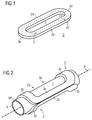
- a flat or flat coil shape of the racetrack type is to be assumed in the production of a saddle-shaped coil winding.
- Corresponding coil shapes are generally known (cf. DE 199 43 783 A1 ); an embodiment shows FIG. 1 ,
- the coil winding 2 ' has opposite longitudinal winding sections 2a' and 2d 'as well as curved end winding sections 2b' and 2c 'extending therebetween.
- the winding 2 ' should be created with one or more band-shaped superconductors.
- the respective strip-shaped conductor is edgewise, ie with its narrow side to the winding plane around a winding or winding center Z, for example, wound around a central winding core.
- a circumferential length of the conductor within an arbitrary turn once around 360 ° around the center Z or once through each of the two longitudinal winding sections 2a ', 2d' and the front winding sections 2b ', 2c' is intended in the figure by a designated U be indicated by dashed line.
- the two edges of the strip each define a circumferential length U1 or U2. In the case of planar winding, these two circulating lengths are inherently the same.
- the at least one band-shaped superconductor be formed with MgB 2 superconductor material.
- one of the known HTS materials is selected.
- the winding 2 ' is therefore formed with one or more band-shaped HTS conductors, in particular of the (BiPb) 2 Sr 2 Ca 2 CuO x type (abbreviation: BPSCCO) or of the YBa 2 Cu 3 O x type (abbreviation: YBCO) ,
- the HTS conductors have a width w, which is typically greater than 3 mm and usually between 3 and 5 mm. Its thickness d is much smaller than the width w and is typically less than 0.5 mm.
- HTS conductors having an aspect ratio (width w / thickness d) of at least 3, preferably at least 5, are preferably used.
- the saddle coil winding according to the invention is now designed so that both circulation lengths U1 and U2 in the case of the three-dimensional coil winding form at most a difference of 0.4%, preferably 0.3% or even better 0.2%, change in length to the circulation lengths the plane coil as well as relative to each other.
- This difference depends on the particular superconductor structure and its change in the superconducting properties during bending or stretching. It can therefore also be below the specified value. In this case, it can be ensured that the local elongation or compression of the strip conductor compared to the flat coil is also not more than 0.4%, preferably 0.3% or even better 0.2% over the entire circulation.
- the circumferential length U of the conductor in the individual windings should remain virtually unchanged with respect to the saddle coil winding to be formed from the flat racetrack coil winding, this means a concrete predefinition of the individual circulating lengths U for the race track coil winding. That is, in the case of the coil winding according to the invention, the circulating lengths to be concretely selected for the conductor or conductors in the individual windings are determined by the corresponding Length of the respective turn is given in the saddle shape and depending on the cycle length is set for the individual turns in the flat racetrack coil shape.
- the conductor windings in the area of the end winding sections 2b ', 2c' must be relatively loosely adjacent to one another, that is, they must not be rigidly connected to one another.
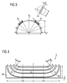
- Each of the coil windings 2 and 3 has, in the direction of the hollow cylinder axis A running, straight winding sections 2a, 2d (not visible) or 3a, 3d (not visible) and curved, winding heads forming winding sections 2b, 2c and 3b, 3c on opposite end sides ,
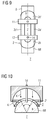
- FIGS. 3 and 4 contains z. B. the selected coil winding 3 straight coil sections 3a of the axial length G and three-dimensionally bent end windings in end winding sections 3b and 3c each have the axial length L.
- the coil winding is located on a cylinder surface Mf of the diameter D.
- the embodiments differ according to the pairs of figures 3, 4 and 5, 6 essentially by the height h of the saddle-shaped coil winding 3.
- the size h represents the maximum value by which the winding heads from the plane of the raise original racetrack coil winding or out of the plane of the longitudinal winding parts before and after the formation of the saddle shape.
- This value should generally be at least 10% of the diameter D of the tube with the tube surface area Mf and may for example be at least 40% of this size.
- the winding lies with its outermost turns W i in the middle, ie at the equator of the cylindrical surface.
- the radial winding height h is smaller than D / 2.
- a radial height h of at least 10% of the pipe diameter D should be selected.
- the coil geometry shown be assigned a rectangular xyz coordinate system, wherein the x-axis in the equatorial plane, the y-axis perpendicular thereto and the z-axis in the axial direction of the cylinder jacket surface are directed (see. FIGS. 3 and 4 ).
- the outer edge of the same tape conductor (index "a") is located on the straight pieces on the cylinder diameter D a ⁇ D i + 2 w .
- w is the width of the ribbon conductor.
- the Verkippungs- or inclination angle ⁇ adjusts itself so that the outer edge undergoes almost no elongation relative to the inner edge.
- FIG. 7 this fact is evident, in this figure is a section of an end-side winding section or winding head 3b of the FIG. 4 shown winding 3 can be seen.
- the inclination angle ⁇ 1 of the inner conductor winding W 1 is smaller than the inclination angle ⁇ 4 of the outer conductor winding W 4th
- the tilting of the strip conductor is now achieved by toroiding the conductor in the winding over its longitudinal axis. This torsion occurs in addition to the bend as additional mechanical stress on the conductor.
- the bending and torsional stiffnesses of known HTS band conductors can be taken into account with the aid of a correction factor k ⁇ 0.5 to 1.5, preferably k ⁇ 0.5 to 1.0.
- FIG. 8 shows in a diagram with equation 8 calculated tilt angle ⁇ theo and the measured at different saddle coil windings tilt angle ⁇ in each case in dependence on the pole angle ⁇ .
- the measured values are entered as square points ⁇ .
- a saddle-shaped coil winding according to the invention can also be produced with coated YBCO conductors. It is also possible that the technology will be applied to composite composite conductors, particularly of the ladder type, if larger coil windings are required.
- the saddle coil winding according to the invention on an optionally only imaginary lateral surface Mf of an elongated hollow cylinder such.
- B. the rotor of an electrical machine such as a motor or generator is located. It may also be the lateral surface of a magnet z.
- B. is the high energy physics.
- the configuration of a saddle coil winding according to the invention and its production method are not necessarily limited to a corresponding shape of the lateral surface. So are deviating from the exact circular shape of the cross section of a hollow cylinder cross-sectional shapes such. B. a more elliptical cross-sectional shape as well as possible, without causing an excessive overstretching of the superconductor must.
- a straight course of the axis A of the tube with the lateral surface Mf is not mandatory to comply.
- a tubular shape with a curved axis which may be provided with saddle coil windings, which may be carried out according to the invention.
- accelerator magnets z.
- curved coil windings are used.
- the longitudinal side, just assumed for the above embodiments winding sections are bent in the coil plane, so that the particle beam can run on a circular path. That is, the axis A of the tubular lateral surface, which is covered with the saddle coil winding, may optionally also be curved.
Landscapes
- Engineering & Computer Science (AREA)
- Power Engineering (AREA)
- Manufacturing & Machinery (AREA)
- Superconductors And Manufacturing Methods Therefor (AREA)
- Windings For Motors And Generators (AREA)
Claims (18)
- Enroulement (2, 3, 13) de bobine en forme de selle, qui est formé d'une forme (2') plane de bobine du type piste sur une surface (Mf) tubulaire d'enveloppe, de manière à avoir des tronçons (2a, 2d; 3a, 3d) d'enroulement du côté longitudinal s'étendant axialement et s'étendant entre eux des tronçons (2b,2c;3b,3c) d'enroulement du côté frontal formant des têtes de bobine, caractérisé en ce que
les spires (Wi) de l'enroulement de bobine- sont formées d'au moins un supraconducteur (5) en forme de ruban, qui, par son petit côté (5a), est tourné vers la surface (Mf) tubulaire d'enveloppe,- et ont, dans la forme en selle, respectivement une longueur de tour, qui est pratiquement inchangée par rapport à la forme (2') plane de bobine, de sorte que, sur la surface (Mf) tubulaire d'enveloppe, le au moins un supraconducteur (5) en forme de ruban est, dans les spires (Wi) dans la région du sommet des tronçons (2b, 2c, 3b, 3c) d'enroulement du côté frontal, incliné par son côté plat d'un angle (β) d'inclinaison par rapport à une normale (N) à la surface (Mf) d'enveloppe dans la direction du centre (Z) de l'enroulement de bobine, l'angle (β1) d'inclinaison pour une spire (W1) se trouvant à l'intérieur étant plus petit que pour une spire (W4) se trouvant à l'extérieur. - Enroulement de bobine suivant la revendication 1, caractérisé en ce qu'il est constitué d'au moins un supraconducteur (5) en forme de ruban sensible à la dilatation.
- Enroulement de bobine suivant la revendication 1 ou 2, caractérisé en ce que le au moins un supraconducteur (5) en forme de ruban est en un matériau supraconducteur à Tc haute.
- Enroulement de bobine suivant la revendication 3, caractérisé en ce que le au moins un supraconducteur (5) à Tc haute est en un matériau de BPSCCO ou d'YBCO.
- Enroulement de bobine suivant la revendication 1 ou 2, caractérisé en ce que le au moins un supraconducteur (5) en forme de ruban est en un matériau supraconducteur en MgB2.
- Enroulement de bobine suivant l'une des revendications précédentes, caractérisé par au moins un supraconducteur (5) en forme de ruban ayant un rapport d'aspect (largeur w/épaisseur d) d'au moins 3, de préférence d'au moins 5.
- Enroulement de bobine suivant l'une des revendications précédentes, caractérisé en ce qu'un tube de section transversale circulaire ou elliptique est formé par la surface (Mf) tubulaire d'enveloppe.
- Enroulement de bobine suivant l'une des revendications précédentes, caractérisé en ce que la surface (Mf) tubulaire d'enveloppe est une surface cylindrique d'enveloppe.
- Enroulement de bobine suivant l'une des revendications 1 à 7, caractérisé en ce qu'un tube ayant un axe incurvé est formé par la surface (Mf) tubulaire d'enveloppe.
- Enroulement de bobine suivant l'une des revendications précédentes, caractérisé en ce que la surface (Mf) tubulaire d'enveloppe est formée d'un corps tubulaire portant l'enroulement.
- Enroulement de bobine suivant l'une des revendications précédentes, caractérisé en ce que la longueur (U) de tour respective dans la forme en selle se différencie de celle dans la forme plane de bobine d'au plus 0,4 %, de préférence d'au plus 0,3%.
- Enroulement de bobine suivant l'une des revendications précédentes, caractérisé par une hauteur (h) radiale, qui représente au moins 10% du diamètre (D) du tube.
- Enroulement de bobine suivant la revendication 12, caractérisé par une hauteur (h) radiale, qui représente au moins 30% du diamètre (D) du tube.
- Enroulement de bobine suivant l'une des revendications précédentes, caractérisé par un agencement dans une machine tournante ou dans un aimant d'un accélérateur, comme un aimant d'accélérateur de Gantry.
- Procédé de fabrication d'un enroulement de bobine suivant l'une des revendications précédentes, caractérisé par les stades suivants, à savoir- formation de la forme (2') plane de bobine en le au moins un supraconducteur (5) en forme de ruban préfabriqué,- déformation sur la surface (Mf) tubulaire d'enveloppe d'un dispositif (7) de flexion en la forme de selle au moyen d'un pressage,- immobilisation des spires (Wi) en la forme de selle.
- Procédé suivant la revendication 15, caractérisé en ce que, dans la formation de la forme (2') plane de bobine dans la région des tronçons (2b',2c') d'enroulement du côté frontal, il est prévu, entre des spires voisines, des intervalles, de manière à avoir, à la déformation et après la déformation, la longueur (U) de tour pratiquement inchangée des diverses spires (Wi).
- Procédé suivant la revendication 16, caractérisé en ce que, pour la formation de la forme plane de bobine, on introduit, pour la mise à distance des spires (Wi) voisines, des entretoises, qui sont retirées avant le stade de déformation.
- Procédé suivant l'une des revendications 15 à 17, caractérisé en ce que, pour l'immobilisation, on coule ou on colle les spires (Wi).
Applications Claiming Priority (3)
| Application Number | Priority Date | Filing Date | Title |
|---|---|---|---|
| DE102005018370 | 2005-04-20 | ||
| DE102006009250A DE102006009250A1 (de) | 2005-04-20 | 2006-02-28 | Sattelförmige Spulenwicklung unter Verwendung von Supraleitern und Verfahren zu ihrer Herstellung |
| PCT/EP2006/061640 WO2006111527A1 (fr) | 2005-04-20 | 2006-04-18 | Bobine enroulee en forme de selle comprenant des supraconducteurs et procede de production de cette bobine |
Publications (2)
| Publication Number | Publication Date |
|---|---|
| EP1872377A1 EP1872377A1 (fr) | 2008-01-02 |
| EP1872377B1 true EP1872377B1 (fr) | 2016-10-19 |
Family
ID=36645682
Family Applications (1)
| Application Number | Title | Priority Date | Filing Date |
|---|---|---|---|
| EP06743321.9A Ceased EP1872377B1 (fr) | 2005-04-20 | 2006-04-18 | Bobine enroulee en forme de selle comprenant des supraconducteurs et procede de production de cette bobine |
Country Status (7)
| Country | Link |
|---|---|
| US (1) | US7741944B2 (fr) |
| EP (1) | EP1872377B1 (fr) |
| KR (1) | KR101282147B1 (fr) |
| CN (1) | CN101164124B (fr) |
| DE (1) | DE102006009250A1 (fr) |
| RU (1) | RU2374711C2 (fr) |
| WO (1) | WO2006111527A1 (fr) |
Families Citing this family (30)
| Publication number | Priority date | Publication date | Assignee | Title |
|---|---|---|---|---|
| JP2010118457A (ja) * | 2008-11-12 | 2010-05-27 | Sumitomo Electric Ind Ltd | 超電導コイルおよび該超電導コイルの製造方法 |
| DE102009009018A1 (de) | 2009-02-16 | 2010-09-16 | Steinert Elektromagnetbau Gmbh | Arbeitsverfahren und Vorrichtung zum Wickeln einer dreidimensional geformten elektrischen Spule aus bandförmigen Leitern und danach gewickelte Spule |
| DE202009002196U1 (de) | 2009-02-16 | 2009-04-23 | Steinert Elektromagnetbau Gmbh | Vorrichtung zum Wickeln einer dreidimensional geformten elektrischen Spule aus bandförmigen Leitern und danach gewickelte Spule |
| JP5407448B2 (ja) * | 2009-03-13 | 2014-02-05 | 住友電気工業株式会社 | 回転機器 |
| JP5402518B2 (ja) * | 2009-10-20 | 2014-01-29 | 住友電気工業株式会社 | 酸化物超電導コイル、酸化物超電導コイル体および回転機 |
| FI20096333A0 (fi) | 2009-12-15 | 2009-12-15 | Abb Oy | Menetelmä sähkökoneen käämivyyhden valmistamiseksi |
| WO2011161743A1 (fr) * | 2010-06-21 | 2011-12-29 | 住友電気工業株式会社 | Bobine magnétique supraconductrice, dispositif rotatif et procédé de fabrication de bobine magnétique supraconductrice |
| US8487486B1 (en) * | 2011-01-24 | 2013-07-16 | Charles Stuart Vann | Folded electromagnetic coil |
| US8637173B2 (en) | 2011-02-21 | 2014-01-28 | Samsung Sdi Co., Ltd. | Battery pack |
| JP5810647B2 (ja) * | 2011-06-09 | 2015-11-11 | 住友電気工業株式会社 | 高温超電導コイルおよび積層型高温超電導コイル |
| CN102820117B (zh) * | 2012-08-20 | 2014-08-06 | 中国科学院等离子体物理研究所 | 用于降低波纹度的楔形截面超导磁体线圈及导体绕制成型方法 |
| JP6139195B2 (ja) * | 2013-03-15 | 2017-05-31 | 株式会社東芝 | 超電導コイル装置 |
| JP6054216B2 (ja) * | 2013-03-15 | 2016-12-27 | 株式会社東芝 | 超電導コイル製造方法および超電導コイル製造装置 |
| JP6275953B2 (ja) * | 2013-04-17 | 2018-02-07 | 株式会社東芝 | 超電導コイル装置 |
| DE102013207222A1 (de) * | 2013-04-22 | 2014-10-23 | Siemens Aktiengesellschaft | Wicklungsträger, elektrische Spule und Verfahren zur Herstellung einer elektrischen Spule |
| JP6309732B2 (ja) | 2013-09-30 | 2018-04-11 | 株式会社東芝 | 巻線装置、巻線方法 |
| JP2014057087A (ja) * | 2013-11-05 | 2014-03-27 | Sumitomo Electric Ind Ltd | 回転機器 |
| GB201515978D0 (en) | 2015-09-09 | 2015-10-21 | Tokamak Energy Ltd | HTS magnet sections |
| CN110622399B (zh) * | 2017-05-03 | 2022-12-06 | 阿特拉斯·科普柯工业技术公司 | 同步电机 |
| WO2019001696A1 (fr) * | 2017-06-28 | 2019-01-03 | Siemens Aktiengesellschaft | Dispositif bobine et support d'enroulement pour rotor à faible nombre de pôles |
| US12311772B2 (en) | 2018-03-19 | 2025-05-27 | Tula eTechnology, Inc. | Pulse modulated control with field weakening for improved machine efficiency |
| US12609646B2 (en) | 2018-03-19 | 2026-04-21 | Tula eTechnology, Inc. | Boosted converter for pulsed electric machine control |
| KR102783720B1 (ko) | 2018-03-19 | 2025-03-18 | 툴라 이테크놀로지 아이엔씨. | 펄스 전기 기계 제어 |
| DE102018206564A1 (de) * | 2018-04-27 | 2019-10-31 | Siemens Aktiengesellschaft | Supraleitende elektrische Spuleneinrichtung sowie Rotor mit Spuleneinrichtung |
| DE102018218727A1 (de) | 2018-10-31 | 2020-04-30 | Siemens Aktiengesellschaft | Elektrische Spule und Anordnung von elektrischen Spulen |
| US20210375541A1 (en) * | 2018-11-05 | 2021-12-02 | Siemens Gamesa Renewable Energy A/S | Electrical machine and method for fabrication of a coil of an electrical machine |
| KR20240025508A (ko) | 2021-06-28 | 2024-02-27 | 툴라 이테크놀로지 아이엔씨. | 전기 기계의 선택적 위상 제어 |
| US12354789B1 (en) | 2022-02-25 | 2025-07-08 | The United States Of America, As Represented By The Secretary Of The Navy | Methods for manufacturing saddle coils |
| EP4497197A4 (fr) * | 2022-03-22 | 2026-02-18 | Tula Technology Inc | Réduction de retard pour machines synchrones à champ enroulé pulsé |
| US12370907B2 (en) | 2023-10-17 | 2025-07-29 | Tula eTechnology, Inc. | On-pulse transition times for pulsed controlled electric machines using boost voltages |
Family Cites Families (25)
| Publication number | Priority date | Publication date | Assignee | Title |
|---|---|---|---|---|
| DE1270688B (de) | 1963-11-01 | 1968-06-20 | Avco Corp | Wicklungstraeger zum Herstellen von sattelfoermigen, supraleitenden, elektrischen Spulen aus einem flachen Leiterband |
| US3270304A (en) * | 1963-11-01 | 1966-08-30 | Avco Corp | Form for supporting saddle-shaped electrical coils |
| DE1514445B2 (de) | 1965-04-17 | 1971-03-11 | Siemens AG, 1000 Berlin u 8000 München | Magnetspule |
| GB1239204A (fr) | 1967-10-04 | 1971-07-14 | ||
| JPS5936803B2 (ja) | 1976-05-17 | 1984-09-06 | 株式会社日立製作所 | くら形コイルの製造方法 |
| SU1021286A1 (ru) * | 1981-06-26 | 1996-05-27 | Всесоюзный научно-исследовательский институт электромеханики | Многорядная компаундированная формованная катушка |
| SU1270809A1 (ru) * | 1983-03-28 | 1986-11-15 | Опытно-Конструкторское Бюро "Горизонт" Отделения "Штиль" | Способ намотки седлообразных обмоток |
| US4554731A (en) * | 1983-11-07 | 1985-11-26 | The United States Of America As Represented By The United States Department Of Energy | Method and apparatus for making superconductive magnet coils |
| US4486676A (en) * | 1984-01-16 | 1984-12-04 | Electric Power Research Institute, Inc. | Superconducting rotor with end turn region intermittent support and cooling assembly |
| SU1365153A1 (ru) * | 1986-01-17 | 1988-01-07 | Предприятие П/Я А-1758 | Способ изготовлени сверхпровод щей обмотки |
| FR2628256A1 (fr) * | 1988-03-07 | 1989-09-08 | Comp Generale Electricite | Conducteur assimilable a un bobinage, en materiau supraconducteur |
| JPH0497506A (ja) * | 1990-08-16 | 1992-03-30 | Mitsubishi Electric Corp | 超電導電磁石コイル |
| JP2560561B2 (ja) * | 1991-04-26 | 1996-12-04 | 株式会社日立製作所 | 超電導コイル装置 |
| RU2033650C1 (ru) * | 1992-07-27 | 1995-04-20 | Научно-исследовательский институт электрофизической аппаратуры им.Д.В.Ефремова | Способ изготовления бескаркасного равнопрочного сверхпроводящего соленоида |
| RU2082242C1 (ru) * | 1995-06-21 | 1997-06-20 | Акционерное общество открытого типа "Энергетический научно-исследовательский институт им.Г.М.Кржижановского" | Сверхпроводящая обмотка |
| GB2331852A (en) * | 1997-11-28 | 1999-06-02 | Asea Brown Boveri | Transformer winding arrangements |
| US5986380A (en) * | 1998-08-26 | 1999-11-16 | General Electric Co. | Mechanical constraints for tapered end turns of a generator rotor |
| US6509819B2 (en) * | 1999-07-23 | 2003-01-21 | American Superconductor Corporation | Rotor assembly including superconducting magnetic coil |
| US7211919B2 (en) * | 1999-08-16 | 2007-05-01 | American Superconductor Corporation | Thermally-conductive stator support structure |
| DE19943783A1 (de) | 1999-09-13 | 2001-03-29 | Siemens Ag | Supraleitungseinrichtung mit einer mehrpoligen Wicklungsanordnung |
| US6489701B1 (en) * | 1999-10-12 | 2002-12-03 | American Superconductor Corporation | Superconducting rotating machines |
| US6590311B1 (en) * | 1999-12-06 | 2003-07-08 | General Electric Company | Cross-shaped rotor shaft for electrical machine |
| US6711421B2 (en) * | 2001-09-25 | 2004-03-23 | General Electric Company | Structural reinforced superconducting ceramic tape and method of making |
| US6894418B2 (en) * | 2002-07-30 | 2005-05-17 | Comprehensive Power, Inc. | Nested stator coils for permanent magnet machines |
| US7078845B2 (en) * | 2004-05-26 | 2006-07-18 | General Electric Company | Optimized drive train for a turbine driven electrical machine |
-
2006
- 2006-02-28 DE DE102006009250A patent/DE102006009250A1/de not_active Withdrawn
- 2006-04-18 RU RU2007142658/09A patent/RU2374711C2/ru not_active IP Right Cessation
- 2006-04-18 EP EP06743321.9A patent/EP1872377B1/fr not_active Ceased
- 2006-04-18 WO PCT/EP2006/061640 patent/WO2006111527A1/fr not_active Ceased
- 2006-04-18 CN CN2006800136081A patent/CN101164124B/zh not_active Expired - Fee Related
- 2006-04-18 US US11/919,005 patent/US7741944B2/en not_active Expired - Fee Related
- 2006-04-18 KR KR1020077026959A patent/KR101282147B1/ko not_active Expired - Fee Related
Also Published As
| Publication number | Publication date |
|---|---|
| RU2007142658A (ru) | 2009-05-27 |
| WO2006111527A1 (fr) | 2006-10-26 |
| KR20080002987A (ko) | 2008-01-04 |
| EP1872377A1 (fr) | 2008-01-02 |
| US7741944B2 (en) | 2010-06-22 |
| CN101164124B (zh) | 2012-06-20 |
| RU2374711C2 (ru) | 2009-11-27 |
| DE102006009250A1 (de) | 2006-11-02 |
| CN101164124A (zh) | 2008-04-16 |
| US20090058592A1 (en) | 2009-03-05 |
| KR101282147B1 (ko) | 2013-07-04 |
Similar Documents
| Publication | Publication Date | Title |
|---|---|---|
| WO2006111527A1 (fr) | Bobine enroulee en forme de selle comprenant des supraconducteurs et procede de production de cette bobine | |
| EP1256159B1 (fr) | Supraconducteur compound a haut t c? entierement transpose et dispositif pour sa fabrication et son utilisation | |
| DE60210572T2 (de) | Wicklung für eine elecktrische Rotationsmaschine, Verfahren zur Herstellung dieser Wicklung, und Verfahren zur Herstellung einer elecktrischen Rotationsmaschine mit solcher Wicklung | |
| DE19934858A1 (de) | Rotierende elektrische Maschine und Verfahren zu deren Herstellung | |
| EP1738376B1 (fr) | Cable supraconducteur et son procede de production | |
| DE102013207222A1 (de) | Wicklungsträger, elektrische Spule und Verfahren zur Herstellung einer elektrischen Spule | |
| WO2023006612A1 (fr) | Procédé pour fabriquer un stator ainsi que stator | |
| DE10157590A1 (de) | Wicklung für einen Transformator oder eine Spule | |
| EP2208280B1 (fr) | Procédé pour fixer un ensemble de segments annulaires à paroi externe cylindrique dans un boîtier annulaire | |
| WO2020187363A1 (fr) | Procédé et dispositif pour réaliser une insertion multicouche d'un mat de bobine dans un composant d'une machine électrique | |
| WO2008028789A1 (fr) | Enroulement armé supraconducteur et procédé pour sa fabrication | |
| DE10260728B4 (de) | Verfahren zur Berechnung des Leiterverlaufs eines Supraleiters vom Spulenkörper zum Joint sowie zugehörige Vorrichtungen | |
| EP1315183B1 (fr) | Enroulement pour un transformateur ou une inductance | |
| DE2100629B2 (de) | Verfahren zur Herstellung einer einlagigen Wicklung und Vorrichtung zur Durchführung des Verfahrens | |
| DE10208564A1 (de) | Luftspule für rotierende elektrische Maschinen und deren Herstellungsverfahren | |
| EP3399528B1 (fr) | Dispositif formant bobine magnétique supraconducteur à plusieurs supraconducteurs en forme de bande enroulés par couches | |
| EP1573887B1 (fr) | Machine electrique dotee d'une bobine a bandage et a refroidir a basse temperature | |
| EP0761009B1 (fr) | Procedes et dispositif pour le bobinage d'un noyau toro dal ferme pour des transformateurs et des bobines de self de puissance elevee | |
| DE102019208227A1 (de) | Verfahren zur Herstellung einer Statorwicklung und Elektromaschine | |
| EP3335228B1 (fr) | Conducteur apte à la supraconduction et utilisation du conducteur apte à la supraconduction | |
| DE20002591U1 (de) | Volltransponierter Hoch-Tc-Verbundsupraleiter sowie Vorrichtung zu dessen Herstellung | |
| EP3142233A1 (fr) | Procede de fabrication d'une bobine formee pour une machine electrique a l'aide de fil plat | |
| EP3176795B1 (fr) | Système de bobines magnétiques comprenant un supraconducteur anisotrope | |
| EP4222846B1 (fr) | Bobine d'une machine électrique et son moyen de fabrication | |
| DE69312541T2 (de) | Kernpaar aus ferromagnetischem Band mit Kegelstumpfartigem Luftspalt für eine elektrische Drehmaschine, insbesondere für einen Asynchronmotor und entsprechendes Herstellungsverfahren |
Legal Events
| Date | Code | Title | Description |
|---|---|---|---|
| PUAI | Public reference made under article 153(3) epc to a published international application that has entered the european phase |
Free format text: ORIGINAL CODE: 0009012 |
|
| 17P | Request for examination filed |
Effective date: 20070910 |
|
| AK | Designated contracting states |
Kind code of ref document: A1 Designated state(s): DE FR GB |
|
| DAX | Request for extension of the european patent (deleted) | ||
| RBV | Designated contracting states (corrected) |
Designated state(s): DE FR GB |
|
| RAP1 | Party data changed (applicant data changed or rights of an application transferred) |
Owner name: SIEMENS AKTIENGESELLSCHAFT |
|
| RAP1 | Party data changed (applicant data changed or rights of an application transferred) |
Owner name: SIEMENS AKTIENGESELLSCHAFT |
|
| GRAP | Despatch of communication of intention to grant a patent |
Free format text: ORIGINAL CODE: EPIDOSNIGR1 |
|
| INTG | Intention to grant announced |
Effective date: 20160511 |
|
| GRAS | Grant fee paid |
Free format text: ORIGINAL CODE: EPIDOSNIGR3 |
|
| GRAA | (expected) grant |
Free format text: ORIGINAL CODE: 0009210 |
|
| AK | Designated contracting states |
Kind code of ref document: B1 Designated state(s): DE FR GB |
|
| REG | Reference to a national code |
Ref country code: GB Ref legal event code: FG4D Free format text: NOT ENGLISH |
|
| REG | Reference to a national code |
Ref country code: DE Ref legal event code: R096 Ref document number: 502006015219 Country of ref document: DE |
|
| REG | Reference to a national code |
Ref country code: FR Ref legal event code: PLFP Year of fee payment: 12 |
|
| REG | Reference to a national code |
Ref country code: DE Ref legal event code: R097 Ref document number: 502006015219 Country of ref document: DE |
|
| PLBE | No opposition filed within time limit |
Free format text: ORIGINAL CODE: 0009261 |
|
| STAA | Information on the status of an ep patent application or granted ep patent |
Free format text: STATUS: NO OPPOSITION FILED WITHIN TIME LIMIT |
|
| RAP2 | Party data changed (patent owner data changed or rights of a patent transferred) |
Owner name: SIEMENS AKTIENGESELLSCHAFT |
|
| 26N | No opposition filed |
Effective date: 20170720 |
|
| REG | Reference to a national code |
Ref country code: DE Ref legal event code: R119 Ref document number: 502006015219 Country of ref document: DE |
|
| GBPC | Gb: european patent ceased through non-payment of renewal fee |
Effective date: 20170418 |
|
| PG25 | Lapsed in a contracting state [announced via postgrant information from national office to epo] |
Ref country code: DE Free format text: LAPSE BECAUSE OF NON-PAYMENT OF DUE FEES Effective date: 20171103 |
|
| PG25 | Lapsed in a contracting state [announced via postgrant information from national office to epo] |
Ref country code: GB Free format text: LAPSE BECAUSE OF NON-PAYMENT OF DUE FEES Effective date: 20170418 |
|
| REG | Reference to a national code |
Ref country code: FR Ref legal event code: PLFP Year of fee payment: 13 |
|
| PGFP | Annual fee paid to national office [announced via postgrant information from national office to epo] |
Ref country code: FR Payment date: 20190425 Year of fee payment: 14 |
|
| PG25 | Lapsed in a contracting state [announced via postgrant information from national office to epo] |
Ref country code: FR Free format text: LAPSE BECAUSE OF NON-PAYMENT OF DUE FEES Effective date: 20200430 |