EP1872919B1 - Centre d'usinage pour usiner des panneaux en bois ou similaire - Google Patents
Centre d'usinage pour usiner des panneaux en bois ou similaire Download PDFInfo
- Publication number
- EP1872919B1 EP1872919B1 EP07110831A EP07110831A EP1872919B1 EP 1872919 B1 EP1872919 B1 EP 1872919B1 EP 07110831 A EP07110831 A EP 07110831A EP 07110831 A EP07110831 A EP 07110831A EP 1872919 B1 EP1872919 B1 EP 1872919B1
- Authority
- EP
- European Patent Office
- Prior art keywords
- bar
- machining
- machining centre
- unit
- along
- Prior art date
- Legal status (The legal status is an assumption and is not a legal conclusion. Google has not performed a legal analysis and makes no representation as to the accuracy of the status listed.)
- Active
Links
Images

Classifications
-
- B—PERFORMING OPERATIONS; TRANSPORTING
- B27—WORKING OR PRESERVING WOOD OR SIMILAR MATERIAL; NAILING OR STAPLING MACHINES IN GENERAL
- B27C—PLANING, DRILLING, MILLING, TURNING OR UNIVERSAL MACHINES FOR WOOD OR SIMILAR MATERIAL
- B27C9/00—Multi-purpose machines; Universal machines; Equipment therefor
- B27C9/04—Multi-purpose machines; Universal machines; Equipment therefor with a plurality of working spindles
-
- B—PERFORMING OPERATIONS; TRANSPORTING
- B23—MACHINE TOOLS; METAL-WORKING NOT OTHERWISE PROVIDED FOR
- B23Q—DETAILS, COMPONENTS, OR ACCESSORIES FOR MACHINE TOOLS, e.g. ARRANGEMENTS FOR COPYING OR CONTROLLING; MACHINE TOOLS IN GENERAL CHARACTERISED BY THE CONSTRUCTION OF PARTICULAR DETAILS OR COMPONENTS; COMBINATIONS OR ASSOCIATIONS OF METAL-WORKING MACHINES, NOT DIRECTED TO A PARTICULAR RESULT
- B23Q1/00—Members which are comprised in the general build-up of a form of machine, particularly relatively large fixed members
- B23Q1/03—Stationary work or tool supports
- B23Q1/037—Stationary work or tool supports comprising series of support elements whose relative distance is adjustable
-
- B—PERFORMING OPERATIONS; TRANSPORTING
- B25—HAND TOOLS; PORTABLE POWER-DRIVEN TOOLS; MANIPULATORS
- B25B—TOOLS OR BENCH DEVICES NOT OTHERWISE PROVIDED FOR, FOR FASTENING, CONNECTING, DISENGAGING, OR HOLDING
- B25B11/00—Work holders not covered by any preceding group in the subclass, e.g. magnetic work holders, vacuum work holders
- B25B11/005—Vacuum work holders
Definitions
- This invention relates to a machining centre for machining panels made of wood or the like in accordance with the preamble of claim 1 (see for example EP-A-0 566 770 ).
- machining centres are used to perform different stock removal processes (routing, vertical and horizontal boring, cutting, etc.) on the panels.
- a machining centre of this kind basically comprises the following:
- the work table and the machining units may be mobile relative to each other along the three principal axes (X, Y, Z) of movement and adjustment, controlled by the control unit.
- a nesting work table is one having a series of "hollows” or similar features, depending on machining requirements and the type of shapes to be obtained, and equipped with air valves that generate the vacuum used to hold down the workpiece.
- the unworked panel is held down on the work table by a vacuum with an interposed auxiliary table made of a breathable material (known in the jargon of the trade as "spoilboard”): this is necessary to avoid damage to the work table for example when the routing bit that makes the through cuts moves along the thickness of the workpiece.
- spokeboard a breathable material
- the bar work table on the other hand, consists of a series of transversal bars mounted slidably on longitudinal beams. Each bar has one or more vacuum hold-down units whose top surface forms the table that supports the panel to be worked. In this case, too, there is a vacuum system obtained by conduits running through the bars and leading out through the vacuum hold-down units generating a vacuum by which the panel is held down.
- the bars can be adjusted for spacing along the main axis X of the machine, while the suction cup units can be slidably positioned on the respective bars along the axis Y transversal to the main axis X.
- This type of vacuum hold down table enables the panel to "float" over the bars while different bits or cutting tools work the edges of the panel and, if the size of the panel allows, also part of its underside.
- each types of work table is used for a different purpose and, in many cases, both tables have to be used to complete work on the panels.
- the nesting table is used to obtain a large number of shaped parts from the unworked panels (usually in series) but the shaped parts must then be placed on bar tables if work has to be done to their edges: for example, routing or horizontal holes which cannot be done on the nesting table because there is not enough space between one shaped part and another.
- the two types of work table have different operating characteristics and very often both have to be used to be able to process panels from start to finish.
- the aim of this invention is to overcome the above mentioned disadvantages by providing a machining centre for panels made of wood or the like, having a work table whose characteristics are such as to optimize cutting of the unworked panel and then allowing the shaped parts obtained to be worked around the edges immediately without moving the shaped parts from the work table.
- a machining centre in particular a machining centre for panels made of wood or the like, comprising the technical characteristics defined in claim 1; preferred embodiments thereof are defined in the dependent claims.
- the machining centre according to the invention labelled 2 in its entirety, is used for machining panels 1 made of wood or the like.
- the machining centre 2 essentially comprises a work table 3 for supporting an unworked panel 1 and at least one machining unit 4 which move relative to each other.
- the machining unit 4 is mounted on a portal frame structure 4a, is mobile along the three main axes X, Y, Z and is equipped with tools 5 acting on the unworked panel 1 to make it into at least one machined workpiece 1a.
- the work table 3 at least comprises:
- a main control unit 12 (illustrated as a block in the accompanying drawings) for controlling the machining centre 2 as a whole and acting at least on the machining unit 4.
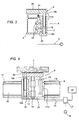
- each vacuum hold-down unit 8 is equipped with means 10 for moving it along the third, vertical axis Z to adopt at least two stable configurations between a first, lowered position where the top surface 8a is close to the respective bar 6 (see Figures 3 and 4 ), and a raised position (see arrow F10), where the top surface 8a is away from the bar 6.
- each bar 6 may be equipped with at least two vacuum hold-down units 8, 8': in this case, each of the two vacuum hold-down units 8, 8' on each bar 6 is equipped with the aforementioned means 10 for moving it along the third vertical axis Z, said means acting, as mentioned above, on the respective top surface 8a forming the work table that supports the panel 1.
- each bar 6 may be slidably mounted on the aforementioned parallel longitudinal beams 7 in such a way that the bars 6 can be positioned stably relative to each other along the first axis X of the machining centre 2 (see arrows F6): obviously, once adjusted, the bars 6 are locked securely in place.
- Adjustment may be done manually by the user by sliding each bar 6 along the first axis X on the beams 7, or automatically by connecting automatic bar 6 movement systems (of known type and not illustrated) to the above mentioned control unit 12.
- each vacuum hold-down unit 8 may also be slidably mounted for adjustment along the respective bar 6, that is to say, along the second axis Y transversal to the first axis X (see arrows F8).
- each vacuum hold-down unit 8, 8' is slidably associated with the respective bar 6 on guides 50 and may be moved by a chain drive system 51.
- each vacuum hold-down unit 8, 8' may be slidably mounted for adjustment along the respective bar 6 which may be done manually by the user or automatically by connecting the drive system 51 directly to the control unit 12.
- each vacuum hold-down unit 8, 8' may be comprised of a carriage 11, slidable along the respective bar 6, and of the top surface 8a: in this case, the vertical movement means 10 may be positioned on the carriage 11.
- the means 10 for movement along the third, vertical axis Z are connected to the above mentioned control unit 12, which controls the movement means 10 themselves in such a way as to coordinate the movements of the top surfaces 8a of one or more vacuum hold-down units 8, 8', thus lifting or lowering the unworked panel 1 (or the shaped parts obtained from the unworked panel 1, as described in more detail below) according to the operating requirements of the machining unit 4.
- the vertical movement means 10 may comprise:
- the actuating element 13 may consist of a double acting air cylinder connected, through respective conduits 15, to a feed source 16 controlled, through valve means 17, by the control unit 12.
- the actuating element 13 may consist of a double acting hydraulic cylinder connected, again through respective conduits 15, to a feed source 16 controlled, again through valve means 17, by the control unit 12.
- the connections of the vacuum generating means must also be adapted to the new configuration.
- the aforementioned vacuum generating means 9 comprise connecting conduits 18 located on each bar 8 and at least one connecting branch 19 extending to the top supporting surface 8a.
- the connecting branch 19 may be comprised of two half parts 19a, 19b, the first part 19a being located on the carriage 11 that mounts the vacuum hold-down unit 8, 8', and the second part 19b being associated with, and leading to, the top supporting surface 8a in such a way as to form a conduit that can be adjusted according to the aforementioned positions adopted by the top surface 8a.
- the second part 19b of the branch 19 may be coaxially inserted in sealed manner into the first part 19a to form a telescoping conduit branch adaptable to the movements of the top surface 8a.
- the second part 19b of the branch 19 is a flexible hose that can be reduced in size (for example, in concertina fashion) and sealed to the top end of the first part 19a.
- the work table 3 structured in this way enables machining of the panel 1 to be carried out as follows.
- the control unit 12 which drives the movement means 10 in such a way as to lift the panel 1 well away from the bars 6 (see arrows F10).
- the machining unit 4 can cut the panel 1 into shaped parts 1a, 1b, 1c (for example), as shown in Figure 2 .
- the unit 12 lowers the vacuum hold-down units 8, 8' supporting the shaped parts that do not need to be worked at that stage (1b, 1c) and keeps the shaped part 1a in the raised position.
- the machining unit 4 can approach the shaped part 1a and move down below the level of its edge without the risk of colliding with the other shaped parts (see Figure 2 ): this procedure can then be repeated on all the remaining shaped parts.
- a machining centre made in this way therefore fully achieves the above mentioned aims thanks to the special structure of the work table.
- the possibility of selectively positioning the vacuum hold-down units along the vertical axis fulfils the twofold purpose of allowing the shaped parts to be cut out without the risk of the cutting tool coming into contact with the work table itself and allowing the edges of each shaped part to be worked in turn by selectively lifting the vacuum hold-down units one at a time while the others are lowered, according to a programmed sequence, without the risk of the machining unit colliding with the other shaped parts.
- This double function of the work table therefore makes it possible to combine the high productivity of a "nesting" table with the versatility of a traditional bar work table: this combination makes the machining centre according to the invention extremely functional, highly productive and advantageously economical in the context of a production line because it allows two machining centres to be substituted with one machine centre without reducing productivity.
Landscapes
- Engineering & Computer Science (AREA)
- Mechanical Engineering (AREA)
- Life Sciences & Earth Sciences (AREA)
- Wood Science & Technology (AREA)
- Forests & Forestry (AREA)
- Machine Tool Units (AREA)
- Laser Beam Processing (AREA)
- Chemical And Physical Treatments For Wood And The Like (AREA)
Claims (12)
- Un centre d'usinage pour des panneaux (1) en bois ou similaire, tel centre d'usinage (2) comprenant une table d'usinage (3) pour le support d'un panneau brut (1) et au moins un groupe d'usinage (4), qui sont mobiles l'un par rapport à l'autre, le groupe (4) étant équipé d'outils (5) agissant sur le panneau brut (1) pour le transformer en au moins une pièce usinée (1a) ; la table d'usinage (3) comprenant au moins :- une pluralité de barres (6) montées sur des poutres longitudinales (7), chaque barre (6) étant montée de façon coulissante sur les poutres longitudinales (7) parallèles de manière à permettre un positionnement relatif stable des barres (6) les unes par rapport aux autres le long d'un premier axe (X) ;- au moins un groupe (8) de maintien par le vide, placé sur chaque barre (6) et dont une surface (8a) supérieure définit la table de support du panneau (1) ; ledit groupe de maintien (8) étant monté de façon coulissante pour pouvoir être réglé le long de la barre (6) respective, c'est-à-dire le long d'un deuxième axe (Y) transversal au premier axe (X) ;- des moyens (9) de génération de vide, agissant sur chaque groupe (8) de maintien par le vide afin d'immobiliser de façon sûre le panneau (1), lesdits moyens (9) de génération de vide comprenant des conduits de raccordement (18) situés sur chaque barre (6) et au moins une branche de raccordement (19) s'étendant jusqu'à la surface supérieure (8a) de support ; chaque groupe (8) de maintien par le vide étant équipé de moyens (10) destinés à le déplacer le long d'un troisième axe (Z) vertical pour lui faire prendre au moins deux configurations stables entre une première position basse dans laquelle la surface supérieure (8a) est à proximité de la barre (6) respective, et une position haute dans laquelle la surface supérieure (8a) est éloignée de la barre (6) ;le centre d'usinage étant caractérisé en ce que la branche de raccordement (19) comprend deux demi-parties (19a, 19b), la première (19a) étant située sur un chariot (11) qui supporte le groupe (8) de maintien par le vide, et la deuxième (19b) étant associée à et débouchant au niveau de la surface supérieure (8a) de support, de manière à former un conduit qui peut être réglé en fonction des positions susmentionnées prises par la surface supérieure (8a) ; la deuxième partie (19b) de la branche (19) étant coaxialement introduite, de façon étanche, dans la première partie (19a) afin de former une branche de conduit télescopique.
- Le centre d'usinage selon la revendication 1, caractérisé en ce que les moyens (10) de déplacement vertical sont situés sur le groupe (8) de maintien par le vide et agissent au moins sur la surface supérieure (8a) définissant la table de support du panneau (1).
- Le centre d'usinage selon la revendication 1, caractérisé en ce que chaque barre (6) est dotée d'au moins deux groupes (8, 8') de maintien par le vide, où chacun des deux groupes (8, 8') de maintien par le vide de chaque barre (6) est équipé des moyens (10) destinés à le déplacer le long du troisième axe (Z) vertical et agissant au moins sur la surface supérieure (8a) définissant la table de support du panneau (1).
- Le centre d'usinage selon la revendication 1, caractérisé en ce que ledit chariot (11) peut coulisser le long de la barre (6) respective et les moyens (10) de déplacement vertical sont situés sur ledit chariot (11).
- Le centre d'usinage selon la revendication 1, comprenant une unité de contrôle maître (12) agissant au moins sur le groupe d'usinage (4), caractérisé en ce que l'unité de contrôle (12) est reliée à et commande les moyens (10) de déplacement le long du troisième axe (Z) vertical de manière à coordonner les déplacements des surfaces supérieures (8a) d'un ou de plusieurs des groupes (8) de maintien par le vide afin de soulever ou d'abaisser au moins un panneau (1) selon les exigences d'usinage du groupe d'usinage (4).
- Le centre d'usinage selon les revendications de 1 à 4, caractérisé en ce que les moyens (10) de déplacement vertical comprennent :- un élément d'actionnement (13) associé au chariot (11) et relié à l'unité de contrôle (12) ;- un guide (14) associé de façon coulissante au chariot (11) et solidaire de la surface supérieure (8a) de support, de manière à permettre le déplacement entre les deux positions de travail, basse et haute, de ladite surface supérieure (8a).
- Le centre d'usinage selon la revendication 6, caractérisé en ce que l'élément d'actionnement (13) est un vérin pneumatique à double effet relié, par l'intermédiaire de conduits (15) respectifs, à une source d'alimentation (16) asservie, par l'intermédiaire de moyens à vanne (17), à l'unité de contrôle (12).
- Le centre d'usinage selon la revendication 6, caractérisé en ce que l'élément d'actionnement (13) est un vérin hydraulique à double effet relié, par l'intermédiaire de conduits (15) respectifs, à une source d'alimentation (16) asservie, par l'intermédiaire de moyens à vanne (17), à l'unité de contrôle (12).
- Le centre d'usinage selon l'une quelconque des revendications précédentes, caractérisé en ce que chaque barre (6) peut être réglée le long du premier axe (X) en la faisant coulisser manuellement le long des poutres (7).
- Le centre d'usinage selon l'une quelconque des revendications précédentes, caractérisé en ce que chaque barre (6) est asservie à l'unité de contrôle (12) de manière à pouvoir être positionnée automatiquement par coulissement sur les poutres (7) le long du premier axe (X).
- Le centre d'usinage selon l'une quelconque des revendications précédentes, caractérisé en ce que chaque groupe (8, 8') de maintien par le vide est asservi à l'unité de contrôle (12) de manière à pouvoir être réglé automatiquement par positionnement sur la barre (6) le long du deuxième axe (Y).
- Le centre d'usinage selon l'une quelconque des revendications précédentes, caractérisé en ce que chaque groupe (8, 8') de maintien par le vide est monté de façon coulissante de manière à pouvoir être réglé manuellement par coulissement sur la barre (6) le long du deuxième axe (Y).
Applications Claiming Priority (1)
| Application Number | Priority Date | Filing Date | Title |
|---|---|---|---|
| IT000491A ITBO20060491A1 (it) | 2006-06-26 | 2006-06-26 | Centro di lavoro per pannelli in legno od assimiliabili. |
Publications (2)
| Publication Number | Publication Date |
|---|---|
| EP1872919A1 EP1872919A1 (fr) | 2008-01-02 |
| EP1872919B1 true EP1872919B1 (fr) | 2009-04-29 |
Family
ID=38521923
Family Applications (1)
| Application Number | Title | Priority Date | Filing Date |
|---|---|---|---|
| EP07110831A Active EP1872919B1 (fr) | 2006-06-26 | 2007-06-22 | Centre d'usinage pour usiner des panneaux en bois ou similaire |
Country Status (4)
| Country | Link |
|---|---|
| EP (1) | EP1872919B1 (fr) |
| DE (1) | DE602007000999D1 (fr) |
| ES (1) | ES2323095T3 (fr) |
| IT (1) | ITBO20060491A1 (fr) |
Families Citing this family (5)
| Publication number | Priority date | Publication date | Assignee | Title |
|---|---|---|---|---|
| ITMO20110275A1 (it) * | 2011-10-28 | 2013-04-29 | Scm Group Spa | Metodo e apparato per lavorare legno |
| ITMO20110276A1 (it) * | 2011-10-28 | 2013-04-29 | Scm Group Spa | Metodo e apparato per lavorare legno |
| ITMO20110274A1 (it) | 2011-10-28 | 2013-04-29 | Scm Group Spa | Metodo e apparato per lavorare legno |
| IT202000016294A1 (it) * | 2020-07-06 | 2022-01-06 | Dario Toncelli | Gruppo di lavoro per la realizzazione di fori in un materiale in lastra e per la lavorazione del bordo interno dei fori e macchina utensile comprendente tale gruppo di lavoro |
| IT202200009287A1 (it) * | 2022-05-06 | 2023-11-06 | Scm Group Spa | Metodo per la determinazione del posizionamento di dispositivi mobili in un piano di lavoro e centro di lavoro che implementa tale metodo. |
Family Cites Families (4)
| Publication number | Priority date | Publication date | Assignee | Title |
|---|---|---|---|---|
| EP0566770A1 (fr) * | 1992-04-24 | 1993-10-27 | Homag Maschinenbau Ag | Procédé et dispositif pour diviser des panneaux et pour l'usinage de ces parties qui en résultant |
| DE4337739C1 (de) * | 1993-11-05 | 1994-08-25 | Klessmann Ima Norte Maschfab | Bearbeitungszentrum zum spangebenden Bearbeiten von plattenförmigen Werkstücken |
| DE10350572A1 (de) * | 2003-10-30 | 2005-06-16 | Wilhelm Altendorf Gmbh & Co. Kg | Aufspanntisch für Werkstücke in einer Werkzeugmaschine |
| DE20321663U1 (de) * | 2003-12-10 | 2009-03-12 | Schwabedissen Maschinen Und Anlagen Service Gmbh | CNC-Bearbeitungsmaschine zum Aufteilen großformatiger Platten |
-
2006
- 2006-06-26 IT IT000491A patent/ITBO20060491A1/it unknown
-
2007
- 2007-06-22 EP EP07110831A patent/EP1872919B1/fr active Active
- 2007-06-22 ES ES07110831T patent/ES2323095T3/es active Active
- 2007-06-22 DE DE602007000999T patent/DE602007000999D1/de active Active
Also Published As
| Publication number | Publication date |
|---|---|
| ES2323095T3 (es) | 2009-07-06 |
| DE602007000999D1 (de) | 2009-06-10 |
| ITBO20060491A1 (it) | 2007-12-27 |
| EP1872919A1 (fr) | 2008-01-02 |
Similar Documents
| Publication | Publication Date | Title |
|---|---|---|
| US11446843B2 (en) | Material loading apparatus | |
| EP2998088B1 (fr) | Centre d'usinage pour dalles en pierre, marbre, matériau synthétique ou similaire avec plan de travail sacrificiel | |
| EP2983879B1 (fr) | Machine-outil multi-axiale pour le travail de dalles et/ou blocks de pierres | |
| US5700117A (en) | Machine tool for machining panels and plates | |
| EP1872919B1 (fr) | Centre d'usinage pour usiner des panneaux en bois ou similaire | |
| US10328607B2 (en) | Machine for cutting stone material | |
| EP2145744A1 (fr) | Dispositif et procédé pour découper des planches. | |
| US20080253871A1 (en) | Robotic work cell and method of operation | |
| EP1651409B1 (fr) | Dispositif a lame circulaire pour couper des feuilles planes de marbre, de granit ou de verre | |
| US5897275A (en) | Machine tool for machining panels and plates | |
| CN201669757U (zh) | 一种木材复合加工中心 | |
| US20150083103A1 (en) | Device for cutting granite or other hard materials | |
| US20060135041A1 (en) | Stonecutting apparatus and method using saw and water jet | |
| CA2584300A1 (fr) | Cellule de travail robotique et methode de fonctionnement | |
| US6688352B2 (en) | Multi-axis work center, for multiple production, in particular for wood working | |
| CN114589352A (zh) | 用于锯开至少一个工件的方法和板分开设备 | |
| KR20170105843A (ko) | 자동 면취장치 | |
| KR100910590B1 (ko) | 양방향 이동이 가능한 다목적 조각기 | |
| CN115366204A (zh) | 一种多自由度钻铣机及其用于木工板材的钻铣方法 | |
| CN212469853U (zh) | 一种自动打孔机构及自动打孔机 | |
| KR100928287B1 (ko) | 브이컷의 다방향 동시 작업이 가능한 조각기 | |
| EP3533571B1 (fr) | Machine pour découper des panneaux en bois ou analogue | |
| CN218365265U (zh) | 一种应用在四边锯上的切割装置及四边锯 | |
| WO2009078053A2 (fr) | Station automatisée de découpe et de traitement de matériau en général | |
| EP4516450A1 (fr) | Systeme d'aspiration de copeaux d'une machine-outil |
Legal Events
| Date | Code | Title | Description |
|---|---|---|---|
| PUAI | Public reference made under article 153(3) epc to a published international application that has entered the european phase |
Free format text: ORIGINAL CODE: 0009012 |
|
| AK | Designated contracting states |
Kind code of ref document: A1 Designated state(s): AT BE BG CH CY CZ DE DK EE ES FI FR GB GR HU IE IS IT LI LT LU LV MC MT NL PL PT RO SE SI SK TR |
|
| AX | Request for extension of the european patent |
Extension state: AL BA HR MK YU |
|
| 17P | Request for examination filed |
Effective date: 20080522 |
|
| 17Q | First examination report despatched |
Effective date: 20080623 |
|
| AKX | Designation fees paid |
Designated state(s): DE ES |
|
| GRAP | Despatch of communication of intention to grant a patent |
Free format text: ORIGINAL CODE: EPIDOSNIGR1 |
|
| GRAS | Grant fee paid |
Free format text: ORIGINAL CODE: EPIDOSNIGR3 |
|
| GRAA | (expected) grant |
Free format text: ORIGINAL CODE: 0009210 |
|
| AK | Designated contracting states |
Kind code of ref document: B1 Designated state(s): DE ES |
|
| REF | Corresponds to: |
Ref document number: 602007000999 Country of ref document: DE Date of ref document: 20090610 Kind code of ref document: P |
|
| REG | Reference to a national code |
Ref country code: ES Ref legal event code: FG2A Ref document number: 2323095 Country of ref document: ES Kind code of ref document: T3 |
|
| PLBE | No opposition filed within time limit |
Free format text: ORIGINAL CODE: 0009261 |
|
| STAA | Information on the status of an ep patent application or granted ep patent |
Free format text: STATUS: NO OPPOSITION FILED WITHIN TIME LIMIT |
|
| 26N | No opposition filed |
Effective date: 20100201 |
|
| P01 | Opt-out of the competence of the unified patent court (upc) registered |
Effective date: 20230518 |
|
| PGFP | Annual fee paid to national office [announced via postgrant information from national office to epo] |
Ref country code: DE Payment date: 20250618 Year of fee payment: 19 |
|
| PGFP | Annual fee paid to national office [announced via postgrant information from national office to epo] |
Ref country code: ES Payment date: 20250718 Year of fee payment: 19 |