EP1873063A2 - Vorrichtung zum Verschließen von Schachteln und dergleichen - Google Patents
Vorrichtung zum Verschließen von Schachteln und dergleichen Download PDFInfo
- Publication number
- EP1873063A2 EP1873063A2 EP07102867A EP07102867A EP1873063A2 EP 1873063 A2 EP1873063 A2 EP 1873063A2 EP 07102867 A EP07102867 A EP 07102867A EP 07102867 A EP07102867 A EP 07102867A EP 1873063 A2 EP1873063 A2 EP 1873063A2
- Authority
- EP
- European Patent Office
- Prior art keywords
- flap
- rotating element
- boxes
- box
- respect
- Prior art date
- Legal status (The legal status is an assumption and is not a legal conclusion. Google has not performed a legal analysis and makes no representation as to the accuracy of the status listed.)
- Granted
Links
Images


Classifications
-
- B—PERFORMING OPERATIONS; TRANSPORTING
- B65—CONVEYING; PACKING; STORING; HANDLING THIN OR FILAMENTARY MATERIAL
- B65B—MACHINES, APPARATUS OR DEVICES FOR, OR METHODS OF, PACKAGING ARTICLES OR MATERIALS; UNPACKING
- B65B39/00—Nozzles, funnels or guides for introducing articles or materials into containers or wrappers
-
- B—PERFORMING OPERATIONS; TRANSPORTING
- B65—CONVEYING; PACKING; STORING; HANDLING THIN OR FILAMENTARY MATERIAL
- B65B—MACHINES, APPARATUS OR DEVICES FOR, OR METHODS OF, PACKAGING ARTICLES OR MATERIALS; UNPACKING
- B65B7/00—Closing containers or receptacles after filling
- B65B7/16—Closing semi-rigid or rigid containers or receptacles not deformed by, or not taking-up shape of, contents, e.g. boxes or cartons
- B65B7/20—Closing semi-rigid or rigid containers or receptacles not deformed by, or not taking-up shape of, contents, e.g. boxes or cartons by folding-down preformed flaps
- B65B7/22—Closing semi-rigid or rigid containers or receptacles not deformed by, or not taking-up shape of, contents, e.g. boxes or cartons by folding-down preformed flaps and inserting flap portions between contents and wall
-
- B—PERFORMING OPERATIONS; TRANSPORTING
- B65—CONVEYING; PACKING; STORING; HANDLING THIN OR FILAMENTARY MATERIAL
- B65B—MACHINES, APPARATUS OR DEVICES FOR, OR METHODS OF, PACKAGING ARTICLES OR MATERIALS; UNPACKING
- B65B1/00—Packaging fluent solid material, e.g. powders, granular or loose fibrous material, loose masses of small articles, in individual containers or receptacles, e.g. bags, sacks, boxes, cartons, cans, or jars
- B65B1/04—Methods of, or means for, filling the material into the containers or receptacles
- B65B1/06—Methods of, or means for, filling the material into the containers or receptacles by gravity flow
-
- B—PERFORMING OPERATIONS; TRANSPORTING
- B05—SPRAYING OR ATOMISING IN GENERAL; APPLYING FLUENT MATERIALS TO SURFACES, IN GENERAL
- B05B—SPRAYING APPARATUS; ATOMISING APPARATUS; NOZZLES
- B05B1/00—Nozzles, spray heads or other outlets, with or without auxiliary devices such as valves, heating means
- B05B1/02—Nozzles, spray heads or other outlets, with or without auxiliary devices such as valves, heating means designed to produce a jet, spray, or other discharge of particular shape or nature, e.g. in single drops, or having an outlet of particular shape
Definitions
- the present invention relates to a device for closing boxes and the like.
- Boxes for packaging products of various kinds are commercially widespread which are traditionally constituted by parallelepipeds made of a material such as cardboard and are provided, at the two end faces, with closure flaps and tabs which mutually interlock.
- Automatic machines which insert products in such boxes currently comprise at least one station where the flaps and tabs are closed after the product to be packaged has been inserted in the box.
- These stations usually comprise closure elements which are operated by crank systems arranged at the two sides of the advancement line of said boxes; the motion of said crank systems defines a path which is suitable to guide the flaps, which are open and extended, in the direction for closure, making them interlock with the tabs provided at the end faces.
- Such elements comprise oscillating masses whose high inertia limits the speed at which they can be operated, mainly due to problems linked to the transmission of vibrations which can become intolerable: this evidently makes it impossible to achieve the ever-increasing production rates currently required by the market.
- said closure elements comprise parts which are specifically intended for direct contact with the product and are sized according to the format of each box that the machine can fill: these parts must of course be adjusted whenever the dimensions of the box change. This need forces to stop production for periods of time currently considered too long in order to perform the adjustments.
- the aim of the present invention is to obviate the above-mentioned drawbacks, by providing a device for closing boxes and the like which allows to increase significantly the packaging speeds with respect to those obtainable with the mechanisms currently being used.
- an object of the present invention is to provide a device for closing boxes which is of universal use and is provided with elements and mechanical parts which can be replaced rapidly and are already adjusted in the correct operating positions, so as to minimize format changing time.
- Another object of the present invention is to provide a device for closing boxes which allows a quick and reliable configuration which persists during operation until the next format change.
- Another object of the present invention is to provide a device which is simple, relatively easy to provide in practice, safe in use, effective in operation, and has a relatively low cost.
- a device for closing boxes and the like of the type suitable to close boxes which are each provided, at at least one end face, with at least one flap with a complementary end flap and with at least two folding lateral tabs which mutually interlock in the closure configuration with the complementary end flap, characterized in that it comprises, arranged laterally with respect to the direction of advancement of said boxes and one after the other, means for folding said flap with respect to the box, at least one first rotating element for folding the complementary flap with respect to the flap, at least one second rotating element for inserting the complementary flap in the mouth of the box, and at least one third rotating element which is suitable to interlock the complementary flap with the tabs, thus providing complete closure of the box.
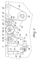
- the reference numeral 1 generally designates a device for closing boxes and the like, according to the invention.
- the device allows to effectively close boxes, each generally designated by the reference numeral 2, which are substantially shaped like a parallelepiped and have at least one mouth at which there is a folding flap 3, a complementary end flap 4 which protrudes from the flap 3, and two folding lateral tabs 5, which are adapted to interlock, in the closed configuration, in lateral notches formed along the folding line between said flap and said complementary flap.
- the device is supported by a footing B of a substantially traditional type and is associated with a line T for conveying the boxes 2 in succession, said line preferably but not exclusively comprising a plurality of receptacles with teeth D which retain each box 2 open in a substantially parallelepipedal configuration.
- the boxes 2 therefore arrive from other preceding production stations where they have been unfolded and are provided with the lateral tabs 5 folded toward the mouth.
- the device according to the invention advantageously comprises, arranged laterally with respect to the advancement direction A of the boxes 2 and in succession one after the other, folding means 6 for folding the flap 3 with respect to the box 2, at least one first rotating element 7 for folding the complementary end flap 4 with respect to the flap 3, at least one second rotating element 8 for insertion of the complementary end flap 4 in the mouth of the box 2, and at least one third rotating element 9, which is suitable to interlock the complementary flap 4 with the tabs 5, thus providing complete closure of the box 2.
- the device is adapted to close the boxes 2 each of which is provided, at two mutually opposite end faces, with the respective flaps 3 with the complementary end flaps 4 and two respective lateral tabs 5 which can fold and mutually interlock in the closure configuration with said complementary end flaps.
- the device can close boxes 2 which have so-called “even” or “alternated” flaps 3, i.e., flaps which protrude respectively from a same side of the parallelepiped or from mutually opposite sides.
- the device according to the invention conveniently comprises, arranged on each of the two sides which are mutually opposite with respect to the advancement direction A of said boxes and in succession one after the other, the means 6 for folding each flap 3 with respect to the box 2, at least one first rotating element 7 for folding each complementary flap 4 with respect to the flap 3, at least one second rotating element 8 for the insertion of each complementary flap 4 in the respective mouth of the box 2, and at least one third rotating element 9, which is suitable to interlock each complementary flap 4 with the respective tabs 5.
- the folding means 6 preferably but not exclusively comprise, for each of the sides, at least one shaped bar S (which is for example bent back with an appropriate inclination), which is substantially parallel to the advancement direction A of the boxes 2 and forms conveniently a profile which is suitable to apply, due to the advancement motion of said boxes, an appropriate pressure against the flap 3 of each box 2.
- the first rotating element 7 is keyed along a respective first shaft 10 by means of a first key 10a; the first shaft 10 is supported so that it can rotate, with a substantially vertical axis, in the footing B of the device laterally to the advancement direction A of the boxes 2 and is associated with respective actuation means, generally designated by the reference numeral 11.
- the coupling of the first rotating element 7 with the first shaft 10, provided by means of the first key 10a, allows to define a specific angular working phase of said first element in relation to a specific format of the box 2 to be closed: said phase must be achieved only once during the tuning of the machine and is maintained whenever a format change is performed, i.e., when the first rotating element 7 is changed in relation to the dimensions of the box 2. This obviously allows to minimize the tuning and adjustment times of the machine.
- first rotating element 7 is associated with a respective disk 11b (which is keyed to the first shaft 10 by means of the key 10a) by way of two slots 12a, 12b, which allow to adapt the phase of the first rotating element 7 to the different characteristics of the boxes to be closed, so as to ensure correct folding of the complementary flap 4 with respect to the flap 3.
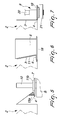
- the first rotating element 7 has a substantially circular shape, with a perimetric edge 13 which forms at least two substantially straight portions 14 and 15 which have an appropriate inclination and are suitable to engage, in the rotation of the first rotating element 7 (concordantly with the advancement of the boxes) on the complementary flap 4, folding it at right angles with respect to the flap 3.
- the first rotating element 7 conveniently has a vertical position which can be adjusted along the first shaft 10 in relation to the dimensions of the box 2 and also in relation to the shape of the box 2, i.e., to the position of the flap 3 with respect to said box.
- the first rotating element 7 is associated with a contrast element 15a which has a substantially triangular transverse cross-section and allows to fold correctly the complementary flap 4 with respect to the flap of each box, as can be deduced intuitively from Figure 5.
- the second rotating element 8 is keyed rigidly along a respective second shaft 16 by means of a second key 16a, the second shaft 16 being supported so that it can rotate, with a substantially vertical axis, in the footing B of the device, laterally to the advancement direction A of the boxes, and being associated with the actuation means 11.
- the second rotating element 8 has a substantially cylindrical contoured shape, in which the lateral surface forms planes 17 which are suitably inclined with respect to the axis of said element, said inclination being studied in relation to the relative motion between the device and each box, suitable to engage, as a consequence of the rotation which is concordant with the advancement of the boxes, against the flap 3, providing such a pressure as to insert the complementary flap 4 in the mouth of the box 2.
- the second rotating element 8 of course can have a lateral surface which forms several planes 17, each having respective areas and inclinations with respect to the axis, or even one or more sectors having a reduced diameter in relation to the specific requirements and the geometries of the boxes, so as to determine a sort of cam-like contact which, by rotation, guides the flap 3, inserting the complementary flap 4 in the mouth.
- the second rotating element 8 is associated advantageously, on one of the faces, with at least one circular plate 18 (see in particular Figure 6), which is suitable to be inserted partially in the mouth of the box 2 so as to keep it sufficiently divaricated to ensure correct insertion of the complementary flap 4 inside it, without sliding which might compromise the correct closure of the boxes.
- the plate 18 is affected by at least one recess 18a which, adjusted with the appropriate phase with respect to the advancement motion of the boxes, allows to avoid interference with the side wall of the box 2.
- the second rotating element 8 can be fixed adjustably with respect to the second shaft 16 by means of slots so as to adapt the phase of said element in relation to the mechanical and dimensional characteristics of the boxes.
- the third rotating element 9 (shown in Figure 7) comprises a disk 19 which is rigidly keyed, by means of a third key 19a, on a third shaft 20, which is supported so that it can rotate in the footing B and is controlled by the actuation means 11.
- the disk 19 is conveniently adapted, in its rotation concordantly with the advancement of the boxes 2, to apply an appropriate pressure to the flap 3 of each box so as to provide the interlocking of the complementary flap 4 with the lateral tabs 5 and achieve complete closure of said box.
- the disk 19 is affected by a recess 20a which, adjusted in appropriate phase with respect to the advancement motion of the boxes, allows to avoid interference with the side wall of the box 2.
- the embodiment described here relates in particular to the closure of boxes with so-called "alternating" flaps; for this purpose, the first rotating element 7, the second rotating element 8 and the third rotating element 9 are arranged, on one side (the right side with respect to the advancement direction), very close to the surface of the footing B, and on the other side (right side with respect to the advancement direction of the boxes) are positioned at an appropriate height in relation to the dimensions of the box.
- the second rotating element 8 and the third rotating element 9 are, along this last side, mounted on a plate-like support 21 with bearings (Figure 3), said support being mounted at an adjustable height by means of a clamp on a rod 22 which is rigidly coupled to the footing B.
- each of the belts 23 is suitable to extract the closed boxes 2 from the respective toothed receptacles D in order to then convey them to the outlet of the box packaging machine.
- the folding means 6 and the first rotating element 7 are associated, for each of their sides, with removable supporting means 27, which allow to replace rapidly and monolithically the parts for each of the formats being produced without having to perform adjustments and fine tuning.
- the supporting means 27 comprise a longitudinal member 28, which is parallel to the advancement direction of the boxes 2 and is fixed adjustably to the footing B in a slot by means of a lever 29 with quick opening and closing; a first arm 30, a second arm 32 and a third arm 34 are fixed adjustably by means of slots to the longitudinal member 28; a first slotted column 31 for vertical adjustable support of the contrast element 15a is rigidly coupled to the first arm 30; a second slotted column 33 for vertical adjustable support of the contoured bar S is rigidly coupled to the second arm 32; a third slotted column 35 is rigidly coupled to the third arm 34.
- the third slotted column 35 supports, so that it can be adjusted vertically, a plate 36 with which the first element 7 is advantageously associated so that it can rotate.
- the contoured bar A, the contrast element 15a and the first rotating element 7 are removed monolithically; this allows to pass rapidly from one format to another in a short time and without further adjustments, since said parts have been fine-tuned beforehand in the correct positions and phases.
- the second rotating element 8 and the third rotating element 9 also can be removed rapidly (slid off their supporting shafts) and replaced with the ones related to the specific format being produced.
- the actuation means 11 comprise at least one pair of bevel gears 37, 38, which mesh together and are adapted to transmit motion from at least one motor, for example an electric motor (supported in the footing B and not shown for the sake of simplicity in the figures, but of a substantially traditional type), to a motor shaft 39, on which the driving roller 24 is mounted.
- at least one motor for example an electric motor (supported in the footing B and not shown for the sake of simplicity in the figures, but of a substantially traditional type), to a motor shaft 39, on which the driving roller 24 is mounted.
- a first toothed pulley 40 is rigidly keyed on the motor shaft 39, while on the first shaft 10 and on the second shaft 16 a second toothed pulley 41 and a third toothed pulley 42 are rigidly coupled respectively; the first pulley 40, the second pulley 41 and the third pulley 42 mesh with a toothed belt 43, which is adjusted by means of a tensioning roller 44 which is fixed adjustably to the footing.
- a lower plate 45 which is fixed below the surface of the footing B, rotatably supports a first gear 46, a second gear 47 and a third gear 48, which constitute a gear system which transmits motion from the second rotating element 8 to the third rotating element 9.
- the first toothed gear 46 is in fact rigidly keyed along the second shaft 16, while the third toothed gear 48 is rigidly keyed along the third shaft 20; the second gear 47 is instead idle.
- Each box 2 advances along the direction A and encounters first the folding means 6, which by passive contrast of the contoured bar 6a fold the flap 3 with respect to the side of the box 2.
- the rotation of the first rotating element 7 subsequently determines, by way of the contact of its portions 14, 15 against the complementary flap 4 and in cooperation with the contrast element 15a, the folding of said contrast element with respect to the flap 3.
- the rotation of the second element 8, in association with the plate 18, subsequently allows insertion of the complementary flap 4 in the mouth of the box; finally, the third rotating element 9 provides the permanent interlocking of the complementary flap 4 with the lateral tabs 5, closing the box 2.
- This sequence of operations occurs of course simultaneously for both sides of the device, i.e., for both mouths of the boxes 2.
- the device allows to close boxes of any size without having to perform mechanical adjustments but merely by performing quick and simple replacements of parts which are already preadjusted in their positions and rotation phases.
- the device allows to increase significantly the speed of the production line, since there are no large oscillating masses, which are typically characterized by vibration problems.
Landscapes
- Engineering & Computer Science (AREA)
- Mechanical Engineering (AREA)
- Closing Of Containers (AREA)
- Making Paper Articles (AREA)
- Folding Of Thin Sheet-Like Materials, Special Discharging Devices, And Others (AREA)
- Supplying Of Containers To The Packaging Station (AREA)
- Cartons (AREA)
Applications Claiming Priority (1)
| Application Number | Priority Date | Filing Date | Title |
|---|---|---|---|
| IT000501A ITBO20060501A1 (it) | 2006-06-30 | 2006-06-30 | Dispositivo per effettuare la chiusura di astucci e simili |
Publications (3)
| Publication Number | Publication Date |
|---|---|
| EP1873063A2 true EP1873063A2 (de) | 2008-01-02 |
| EP1873063A3 EP1873063A3 (de) | 2009-03-25 |
| EP1873063B1 EP1873063B1 (de) | 2011-07-27 |
Family
ID=38541923
Family Applications (1)
| Application Number | Title | Priority Date | Filing Date |
|---|---|---|---|
| EP07102867A Active EP1873063B1 (de) | 2006-06-30 | 2007-02-22 | Vorrichtung zum Verschließen von Schachteln und dergleichen |
Country Status (9)
| Country | Link |
|---|---|
| US (1) | US7328546B2 (de) |
| EP (1) | EP1873063B1 (de) |
| JP (1) | JP5123562B2 (de) |
| KR (1) | KR101333098B1 (de) |
| CN (1) | CN101096226B (de) |
| AT (1) | ATE517814T1 (de) |
| BR (1) | BRPI0701986A (de) |
| ES (1) | ES2370208T3 (de) |
| IT (1) | ITBO20060501A1 (de) |
Cited By (3)
| Publication number | Priority date | Publication date | Assignee | Title |
|---|---|---|---|---|
| CN103057734A (zh) * | 2013-02-04 | 2013-04-24 | 福州大学 | 一种变胞式纸浆包装作角机构 |
| CN103359327A (zh) * | 2013-07-30 | 2013-10-23 | 苏州经贸职业技术学院 | 一种纸箱撑开封口系统 |
| IT201600094659A1 (it) * | 2016-09-21 | 2018-03-21 | S P Automation S R L A Socio Unico | Sistema e procedimento di chiusura di scatole |
Families Citing this family (10)
| Publication number | Priority date | Publication date | Assignee | Title |
|---|---|---|---|---|
| PL2419334T3 (pl) * | 2009-04-15 | 2020-08-24 | Packsize, Llc | Środek pomocniczy do ustawiania do pozycji pionowej |
| CN102556388B (zh) * | 2011-01-19 | 2013-10-02 | 上海龙腾机械制造有限公司 | 一种封盒机构 |
| CN103434667B (zh) * | 2013-08-23 | 2015-08-19 | 中山市恒鑫聚诚工业设备有限公司 | 一种用于包装箱底部自动折盒机 |
| GB201319551D0 (en) * | 2013-11-05 | 2013-12-18 | Elopak Systems | Improvements in or relating to packaging |
| CN103935540A (zh) * | 2014-04-24 | 2014-07-23 | 江苏凯特莉包装科技有限公司 | 一种自动包装机药盒关盒装置 |
| CN106081194B (zh) * | 2016-06-30 | 2024-01-26 | 上海金谦机械技术有限公司 | 镜片装盒设备的镜盒合盖机构 |
| CN111434486A (zh) * | 2019-01-11 | 2020-07-21 | 广东鸿铭智能股份有限公司 | 一种全自动整形贴卡机的气动抱盒机构 |
| CN111792109B (zh) * | 2019-03-13 | 2022-04-26 | 楼玲燕 | 一种纸箱包装机构 |
| CN115008835B (zh) * | 2022-06-15 | 2025-06-20 | 河北喜之郎食品有限公司 | 一种单杯纸托的自动折托设备 |
| WO2026033431A1 (en) * | 2024-08-08 | 2026-02-12 | Marchesini Group S.P.A. | A folding unit for folding a tuck-in closing flap of a head of boxes in tubular configuration |
Family Cites Families (19)
| Publication number | Priority date | Publication date | Assignee | Title |
|---|---|---|---|---|
| US2625778A (en) * | 1951-05-21 | 1953-01-20 | Sutherland Paper Co | Machine for closing cartons while the cartons are being translated |
| US2669167A (en) * | 1952-12-03 | 1954-02-16 | Sutherland Paper Co | Machine for erecting double side walls on double walled cartons |
| US2948094A (en) * | 1956-01-11 | 1960-08-09 | Diamond National Corp | Packaging |
| US3421288A (en) * | 1965-01-14 | 1969-01-14 | Bivans Corp | Carton-closing machine |
| JPS491797Y1 (de) * | 1970-06-12 | 1974-01-17 | ||
| JPS4996895A (de) * | 1973-01-20 | 1974-09-13 | ||
| DE2500392A1 (de) * | 1975-01-07 | 1976-07-15 | Wilhelm Ing Grad Schuster | Verpackungsmaschine |
| US4441303A (en) * | 1982-02-03 | 1984-04-10 | H. J. Langen & Sons Limited | Carton-closing machine |
| US4805375A (en) * | 1987-12-16 | 1989-02-21 | H. J. Langen & Sons Limited | Carton end closure |
| JPH02102304U (de) * | 1989-01-31 | 1990-08-15 | ||
| JPH0786004B2 (ja) * | 1990-06-11 | 1995-09-20 | 澁谷工業株式会社 | フラップ差し込み装置 |
| IT1257844B (it) * | 1992-06-24 | 1996-02-13 | Amrp Handels Ag | Meccanismo per snervare, piegare e introdurre il lembo di chiusura di una scatola nell'apertura corrispondente di tale scatola |
| US5595043A (en) * | 1994-11-14 | 1997-01-21 | R.A. Jones & Co., Inc. | Cartoner with selectively interchangeable tucking and gluing modules |
| JP3508297B2 (ja) * | 1995-05-18 | 2004-03-22 | 澁谷工業株式会社 | 箱体のフラップ折込み装置 |
| JPH09249201A (ja) * | 1996-03-14 | 1997-09-22 | Kanebo Ltd | カートンの蓋閉装置 |
| IT1285814B1 (it) * | 1996-07-22 | 1998-06-24 | Baumer Srl | Dispositivo incollatore - piegatore per piegare i e per applicare collante sui lembi di chiusura dei fustellati nelle incartonatrici |
| US6067773A (en) * | 1997-07-15 | 2000-05-30 | 3M Innovative Properties Company | Semi-automatic random box sealer |
| ITBO20010098A1 (it) * | 2001-02-23 | 2002-08-23 | Ima Spa | Metodo per la chiusura di un astuccio mediante piegatura di una relativa aletta laterale di chiusura, e dispositivo che attua tale metodo |
| DE102005019894B4 (de) * | 2005-04-29 | 2010-07-08 | Mediseal Gmbh | Verfahren und Vorrichtung zum Schließen einer Faltschachtel während ihrer kontinuierlichen Förderung |
-
2006
- 2006-06-30 IT IT000501A patent/ITBO20060501A1/it unknown
-
2007
- 2007-02-22 EP EP07102867A patent/EP1873063B1/de active Active
- 2007-02-22 US US11/709,088 patent/US7328546B2/en active Active
- 2007-02-22 AT AT07102867T patent/ATE517814T1/de not_active IP Right Cessation
- 2007-02-22 ES ES07102867T patent/ES2370208T3/es active Active
- 2007-02-28 KR KR1020070020338A patent/KR101333098B1/ko active Active
- 2007-03-01 CN CN2007100876167A patent/CN101096226B/zh active Active
- 2007-03-30 BR BRPI0701986-6A patent/BRPI0701986A/pt not_active IP Right Cessation
- 2007-05-18 JP JP2007132726A patent/JP5123562B2/ja active Active
Cited By (4)
| Publication number | Priority date | Publication date | Assignee | Title |
|---|---|---|---|---|
| CN103057734A (zh) * | 2013-02-04 | 2013-04-24 | 福州大学 | 一种变胞式纸浆包装作角机构 |
| CN103359327A (zh) * | 2013-07-30 | 2013-10-23 | 苏州经贸职业技术学院 | 一种纸箱撑开封口系统 |
| IT201600094659A1 (it) * | 2016-09-21 | 2018-03-21 | S P Automation S R L A Socio Unico | Sistema e procedimento di chiusura di scatole |
| EP3299302A1 (de) * | 2016-09-21 | 2018-03-28 | S.P. Automation S.r.l. a Socio Unico | Schachtelverschliesssystem und -verfahren |
Also Published As
| Publication number | Publication date |
|---|---|
| ATE517814T1 (de) | 2011-08-15 |
| EP1873063A3 (de) | 2009-03-25 |
| ES2370208T3 (es) | 2011-12-13 |
| US7328546B2 (en) | 2008-02-12 |
| JP5123562B2 (ja) | 2013-01-23 |
| CN101096226A (zh) | 2008-01-02 |
| ITBO20060501A1 (it) | 2008-01-01 |
| BRPI0701986A (pt) | 2008-02-19 |
| CN101096226B (zh) | 2013-04-24 |
| US20080000197A1 (en) | 2008-01-03 |
| KR101333098B1 (ko) | 2013-11-26 |
| JP2008013260A (ja) | 2008-01-24 |
| KR20080003194A (ko) | 2008-01-07 |
| EP1873063B1 (de) | 2011-07-27 |
Similar Documents
| Publication | Publication Date | Title |
|---|---|---|
| EP1873063B1 (de) | Vorrichtung zum Verschließen von Schachteln und dergleichen | |
| US3325977A (en) | Packing machine | |
| EP3015373B1 (de) | Automatische schliessgruppe für durch stanzung geformte deckel von pappkartons | |
| US5671593A (en) | Semiautomatic package wrapping machine | |
| EP2829481B1 (de) | Verpackungsverfahren und Einheit zur Zuführung eines Zuschnitts in einer Verpackungsmaschine | |
| EP0576404B1 (de) | Vorrichtung zum Falzen eines Verschlusslappens einer Schachtel und zum Einstecken des Verschlusslappens in eine entsprechende Öffnung der Schachtel | |
| EP0995682B1 (de) | Antriebsmechanismus für Faltaggregat in einer Verpackungsmachine | |
| CN204415788U (zh) | 一种用于硬币成卷的包装机 | |
| JP2017504531A (ja) | マガジンからキャリアへカートンブランクを搬送するための装置及び方法 | |
| US4085569A (en) | Device for preparing pieces of wrapping material for use as the inner wrap in hinge lid cigarette packs | |
| EP0569340B1 (de) | Schachtelgreifvorrichtung in einer automatischen Verpackungsmaschine | |
| ITBO20060056A1 (it) | Dispositivo di taglio per articoli da fumo. | |
| EP1584455B1 (de) | Vorrichtung zum Herstellen von Schachteln | |
| US4167994A (en) | Conveyor for feeding preshaped cardboard pieces | |
| EP0978449B1 (de) | Maschine zum Verpacken von Artikeln in Schachteln | |
| EP1868896B1 (de) | Maschine mit drehkopf zur verpackung von produkten in versiegelter folie | |
| CN103723305A (zh) | 全自动封装机 | |
| EP1300088B1 (de) | Abgabeeinheit für eine Zigarettenherstellungsmaschine | |
| WO2013088405A1 (en) | A device for making a longitudinal fin on a corresponding product wrapper | |
| US2189087A (en) | Continuous motion wrapping machine | |
| EP2441690A1 (de) | Kartoniermaschine | |
| GB2058706A (en) | Carton Erecting Machines | |
| CS199261B2 (en) | Equipment for manufacture of packing pieces dimension g | |
| EP1533232B1 (de) | Verpackungsvorrichtung | |
| CN213832350U (zh) | 一种封合出料装置 |
Legal Events
| Date | Code | Title | Description |
|---|---|---|---|
| PUAI | Public reference made under article 153(3) epc to a published international application that has entered the european phase |
Free format text: ORIGINAL CODE: 0009012 |
|
| AK | Designated contracting states |
Kind code of ref document: A2 Designated state(s): AT BE BG CH CY CZ DE DK EE ES FI FR GB GR HU IE IS IT LI LT LU LV MC NL PL PT RO SE SI SK TR |
|
| AX | Request for extension of the european patent |
Extension state: AL BA HR MK YU |
|
| PUAL | Search report despatched |
Free format text: ORIGINAL CODE: 0009013 |
|
| AK | Designated contracting states |
Kind code of ref document: A3 Designated state(s): AT BE BG CH CY CZ DE DK EE ES FI FR GB GR HU IE IS IT LI LT LU LV MC NL PL PT RO SE SI SK TR |
|
| AX | Request for extension of the european patent |
Extension state: AL BA HR MK RS |
|
| 17P | Request for examination filed |
Effective date: 20090917 |
|
| AKX | Designation fees paid |
Designated state(s): AT BE BG CH CY CZ DE DK EE ES FI FR GB GR HU IE IS IT LI LT LU LV MC NL PL PT RO SE SI SK TR |
|
| GRAP | Despatch of communication of intention to grant a patent |
Free format text: ORIGINAL CODE: EPIDOSNIGR1 |
|
| GRAS | Grant fee paid |
Free format text: ORIGINAL CODE: EPIDOSNIGR3 |
|
| GRAA | (expected) grant |
Free format text: ORIGINAL CODE: 0009210 |
|
| AK | Designated contracting states |
Kind code of ref document: B1 Designated state(s): AT BE BG CH CY CZ DE DK EE ES FI FR GB GR HU IE IS IT LI LT LU LV MC NL PL PT RO SE SI SK TR |
|
| REG | Reference to a national code |
Ref country code: GB Ref legal event code: FG4D |
|
| REG | Reference to a national code |
Ref country code: CH Ref legal event code: EP |
|
| REG | Reference to a national code |
Ref country code: DE Ref legal event code: R096 Ref document number: 602007016030 Country of ref document: DE Effective date: 20110929 |
|
| REG | Reference to a national code |
Ref country code: NL Ref legal event code: VDEP Effective date: 20110727 |
|
| REG | Reference to a national code |
Ref country code: ES Ref legal event code: FG2A Ref document number: 2370208 Country of ref document: ES Kind code of ref document: T3 Effective date: 20111213 |
|
| REG | Reference to a national code |
Ref country code: AT Ref legal event code: MK05 Ref document number: 517814 Country of ref document: AT Kind code of ref document: T Effective date: 20110727 |
|
| PG25 | Lapsed in a contracting state [announced via postgrant information from national office to epo] |
Ref country code: FI Free format text: LAPSE BECAUSE OF FAILURE TO SUBMIT A TRANSLATION OF THE DESCRIPTION OR TO PAY THE FEE WITHIN THE PRESCRIBED TIME-LIMIT Effective date: 20110727 Ref country code: LT Free format text: LAPSE BECAUSE OF FAILURE TO SUBMIT A TRANSLATION OF THE DESCRIPTION OR TO PAY THE FEE WITHIN THE PRESCRIBED TIME-LIMIT Effective date: 20110727 Ref country code: BE Free format text: LAPSE BECAUSE OF FAILURE TO SUBMIT A TRANSLATION OF THE DESCRIPTION OR TO PAY THE FEE WITHIN THE PRESCRIBED TIME-LIMIT Effective date: 20110727 Ref country code: SE Free format text: LAPSE BECAUSE OF FAILURE TO SUBMIT A TRANSLATION OF THE DESCRIPTION OR TO PAY THE FEE WITHIN THE PRESCRIBED TIME-LIMIT Effective date: 20110727 Ref country code: NL Free format text: LAPSE BECAUSE OF FAILURE TO SUBMIT A TRANSLATION OF THE DESCRIPTION OR TO PAY THE FEE WITHIN THE PRESCRIBED TIME-LIMIT Effective date: 20110727 Ref country code: PT Free format text: LAPSE BECAUSE OF FAILURE TO SUBMIT A TRANSLATION OF THE DESCRIPTION OR TO PAY THE FEE WITHIN THE PRESCRIBED TIME-LIMIT Effective date: 20111128 Ref country code: IS Free format text: LAPSE BECAUSE OF FAILURE TO SUBMIT A TRANSLATION OF THE DESCRIPTION OR TO PAY THE FEE WITHIN THE PRESCRIBED TIME-LIMIT Effective date: 20111127 |
|
| PG25 | Lapsed in a contracting state [announced via postgrant information from national office to epo] |
Ref country code: PL Free format text: LAPSE BECAUSE OF FAILURE TO SUBMIT A TRANSLATION OF THE DESCRIPTION OR TO PAY THE FEE WITHIN THE PRESCRIBED TIME-LIMIT Effective date: 20110727 Ref country code: CY Free format text: LAPSE BECAUSE OF FAILURE TO SUBMIT A TRANSLATION OF THE DESCRIPTION OR TO PAY THE FEE WITHIN THE PRESCRIBED TIME-LIMIT Effective date: 20110727 Ref country code: SI Free format text: LAPSE BECAUSE OF FAILURE TO SUBMIT A TRANSLATION OF THE DESCRIPTION OR TO PAY THE FEE WITHIN THE PRESCRIBED TIME-LIMIT Effective date: 20110727 Ref country code: GR Free format text: LAPSE BECAUSE OF FAILURE TO SUBMIT A TRANSLATION OF THE DESCRIPTION OR TO PAY THE FEE WITHIN THE PRESCRIBED TIME-LIMIT Effective date: 20111028 Ref country code: AT Free format text: LAPSE BECAUSE OF FAILURE TO SUBMIT A TRANSLATION OF THE DESCRIPTION OR TO PAY THE FEE WITHIN THE PRESCRIBED TIME-LIMIT Effective date: 20110727 Ref country code: LV Free format text: LAPSE BECAUSE OF FAILURE TO SUBMIT A TRANSLATION OF THE DESCRIPTION OR TO PAY THE FEE WITHIN THE PRESCRIBED TIME-LIMIT Effective date: 20110727 |
|
| PG25 | Lapsed in a contracting state [announced via postgrant information from national office to epo] |
Ref country code: CZ Free format text: LAPSE BECAUSE OF FAILURE TO SUBMIT A TRANSLATION OF THE DESCRIPTION OR TO PAY THE FEE WITHIN THE PRESCRIBED TIME-LIMIT Effective date: 20110727 Ref country code: SK Free format text: LAPSE BECAUSE OF FAILURE TO SUBMIT A TRANSLATION OF THE DESCRIPTION OR TO PAY THE FEE WITHIN THE PRESCRIBED TIME-LIMIT Effective date: 20110727 |
|
| PG25 | Lapsed in a contracting state [announced via postgrant information from national office to epo] |
Ref country code: EE Free format text: LAPSE BECAUSE OF FAILURE TO SUBMIT A TRANSLATION OF THE DESCRIPTION OR TO PAY THE FEE WITHIN THE PRESCRIBED TIME-LIMIT Effective date: 20110727 Ref country code: RO Free format text: LAPSE BECAUSE OF FAILURE TO SUBMIT A TRANSLATION OF THE DESCRIPTION OR TO PAY THE FEE WITHIN THE PRESCRIBED TIME-LIMIT Effective date: 20110727 |
|
| PLBE | No opposition filed within time limit |
Free format text: ORIGINAL CODE: 0009261 |
|
| STAA | Information on the status of an ep patent application or granted ep patent |
Free format text: STATUS: NO OPPOSITION FILED WITHIN TIME LIMIT |
|
| PG25 | Lapsed in a contracting state [announced via postgrant information from national office to epo] |
Ref country code: DK Free format text: LAPSE BECAUSE OF FAILURE TO SUBMIT A TRANSLATION OF THE DESCRIPTION OR TO PAY THE FEE WITHIN THE PRESCRIBED TIME-LIMIT Effective date: 20110727 |
|
| 26N | No opposition filed |
Effective date: 20120502 |
|
| REG | Reference to a national code |
Ref country code: DE Ref legal event code: R097 Ref document number: 602007016030 Country of ref document: DE Effective date: 20120502 |
|
| PG25 | Lapsed in a contracting state [announced via postgrant information from national office to epo] |
Ref country code: MC Free format text: LAPSE BECAUSE OF NON-PAYMENT OF DUE FEES Effective date: 20120229 |
|
| REG | Reference to a national code |
Ref country code: CH Ref legal event code: PL |
|
| PG25 | Lapsed in a contracting state [announced via postgrant information from national office to epo] |
Ref country code: LI Free format text: LAPSE BECAUSE OF NON-PAYMENT OF DUE FEES Effective date: 20120229 Ref country code: CH Free format text: LAPSE BECAUSE OF NON-PAYMENT OF DUE FEES Effective date: 20120229 |
|
| REG | Reference to a national code |
Ref country code: IE Ref legal event code: MM4A |
|
| PG25 | Lapsed in a contracting state [announced via postgrant information from national office to epo] |
Ref country code: IE Free format text: LAPSE BECAUSE OF NON-PAYMENT OF DUE FEES Effective date: 20120222 |
|
| PG25 | Lapsed in a contracting state [announced via postgrant information from national office to epo] |
Ref country code: BG Free format text: LAPSE BECAUSE OF FAILURE TO SUBMIT A TRANSLATION OF THE DESCRIPTION OR TO PAY THE FEE WITHIN THE PRESCRIBED TIME-LIMIT Effective date: 20111027 |
|
| PG25 | Lapsed in a contracting state [announced via postgrant information from national office to epo] |
Ref country code: LU Free format text: LAPSE BECAUSE OF NON-PAYMENT OF DUE FEES Effective date: 20120222 |
|
| PGFP | Annual fee paid to national office [announced via postgrant information from national office to epo] |
Ref country code: TR Payment date: 20140210 Year of fee payment: 8 |
|
| PG25 | Lapsed in a contracting state [announced via postgrant information from national office to epo] |
Ref country code: HU Free format text: LAPSE BECAUSE OF FAILURE TO SUBMIT A TRANSLATION OF THE DESCRIPTION OR TO PAY THE FEE WITHIN THE PRESCRIBED TIME-LIMIT Effective date: 20070222 |
|
| REG | Reference to a national code |
Ref country code: FR Ref legal event code: PLFP Year of fee payment: 10 |
|
| REG | Reference to a national code |
Ref country code: FR Ref legal event code: PLFP Year of fee payment: 11 |
|
| PG25 | Lapsed in a contracting state [announced via postgrant information from national office to epo] |
Ref country code: TR Free format text: LAPSE BECAUSE OF NON-PAYMENT OF DUE FEES Effective date: 20150222 |
|
| REG | Reference to a national code |
Ref country code: FR Ref legal event code: PLFP Year of fee payment: 12 |
|
| PGFP | Annual fee paid to national office [announced via postgrant information from national office to epo] |
Ref country code: GB Payment date: 20260210 Year of fee payment: 20 |
|
| PGFP | Annual fee paid to national office [announced via postgrant information from national office to epo] |
Ref country code: ES Payment date: 20260306 Year of fee payment: 20 |
|
| PGFP | Annual fee paid to national office [announced via postgrant information from national office to epo] |
Ref country code: DE Payment date: 20260211 Year of fee payment: 20 |
|
| PGFP | Annual fee paid to national office [announced via postgrant information from national office to epo] |
Ref country code: IT Payment date: 20260127 Year of fee payment: 20 |
|
| PGFP | Annual fee paid to national office [announced via postgrant information from national office to epo] |
Ref country code: FR Payment date: 20260210 Year of fee payment: 20 |