EP1873542A1 - Appareil et méthode pour évaluer l'état de charge d'une pile - Google Patents
Appareil et méthode pour évaluer l'état de charge d'une pile Download PDFInfo
- Publication number
- EP1873542A1 EP1873542A1 EP07111015A EP07111015A EP1873542A1 EP 1873542 A1 EP1873542 A1 EP 1873542A1 EP 07111015 A EP07111015 A EP 07111015A EP 07111015 A EP07111015 A EP 07111015A EP 1873542 A1 EP1873542 A1 EP 1873542A1
- Authority
- EP
- European Patent Office
- Prior art keywords
- state
- battery
- soc
- charge
- charging
- Prior art date
- Legal status (The legal status is an assumption and is not a legal conclusion. Google has not performed a legal analysis and makes no representation as to the accuracy of the status listed.)
- Granted
Links
Images


Classifications
-
- G—PHYSICS
- G01—MEASURING; TESTING
- G01R—MEASURING ELECTRIC VARIABLES; MEASURING MAGNETIC VARIABLES
- G01R31/00—Arrangements for testing electric properties; Arrangements for locating electric faults; Arrangements for electrical testing characterised by what is being tested not provided for elsewhere
- G01R31/36—Arrangements for testing, measuring or monitoring the electrical condition of accumulators or electric batteries, e.g. capacity or state of charge [SoC]
- G01R31/382—Arrangements for monitoring battery or accumulator variables, e.g. SoC
- G01R31/3842—Arrangements for monitoring battery or accumulator variables, e.g. SoC combining voltage and current measurements
-
- H—ELECTRICITY
- H02—GENERATION; CONVERSION OR DISTRIBUTION OF ELECTRIC POWER
- H02J—ELECTRIC POWER NETWORKS; CIRCUIT ARRANGEMENTS OR SYSTEMS FOR SUPPLYING OR DISTRIBUTING ELECTRIC POWER; SYSTEMS FOR STORING ELECTRIC ENERGY
- H02J7/00—Circuit arrangements for charging or discharging batteries or for supplying loads from batteries
-
- B—PERFORMING OPERATIONS; TRANSPORTING
- B60—VEHICLES IN GENERAL
- B60L—PROPULSION OF ELECTRICALLY-PROPELLED VEHICLES; SUPPLYING ELECTRIC POWER FOR AUXILIARY EQUIPMENT OF ELECTRICALLY-PROPELLED VEHICLES; ELECTRODYNAMIC BRAKE SYSTEMS FOR VEHICLES IN GENERAL; MAGNETIC SUSPENSION OR LEVITATION FOR VEHICLES; MONITORING OPERATING VARIABLES OF ELECTRICALLY-PROPELLED VEHICLES; ELECTRIC SAFETY DEVICES FOR ELECTRICALLY-PROPELLED VEHICLES
- B60L58/00—Methods or circuit arrangements for monitoring or controlling batteries or fuel cells, specially adapted for electric vehicles
- B60L58/10—Methods or circuit arrangements for monitoring or controlling batteries or fuel cells, specially adapted for electric vehicles for monitoring or controlling batteries
- B60L58/12—Methods or circuit arrangements for monitoring or controlling batteries or fuel cells, specially adapted for electric vehicles for monitoring or controlling batteries responding to state of charge [SoC]
- B60L58/15—Preventing overcharging
-
- G—PHYSICS
- G01—MEASURING; TESTING
- G01R—MEASURING ELECTRIC VARIABLES; MEASURING MAGNETIC VARIABLES
- G01R31/00—Arrangements for testing electric properties; Arrangements for locating electric faults; Arrangements for electrical testing characterised by what is being tested not provided for elsewhere
- G01R31/36—Arrangements for testing, measuring or monitoring the electrical condition of accumulators or electric batteries, e.g. capacity or state of charge [SoC]
-
- H—ELECTRICITY
- H02—GENERATION; CONVERSION OR DISTRIBUTION OF ELECTRIC POWER
- H02J—ELECTRIC POWER NETWORKS; CIRCUIT ARRANGEMENTS OR SYSTEMS FOR SUPPLYING OR DISTRIBUTING ELECTRIC POWER; SYSTEMS FOR STORING ELECTRIC ENERGY
- H02J7/00—Circuit arrangements for charging or discharging batteries or for supplying loads from batteries
- H02J7/14—Circuit arrangements for charging or discharging batteries or for supplying loads from batteries for charging batteries from dynamo-electric generators driven at varying speed, e.g. on vehicle
-
- B—PERFORMING OPERATIONS; TRANSPORTING
- B60—VEHICLES IN GENERAL
- B60L—PROPULSION OF ELECTRICALLY-PROPELLED VEHICLES; SUPPLYING ELECTRIC POWER FOR AUXILIARY EQUIPMENT OF ELECTRICALLY-PROPELLED VEHICLES; ELECTRODYNAMIC BRAKE SYSTEMS FOR VEHICLES IN GENERAL; MAGNETIC SUSPENSION OR LEVITATION FOR VEHICLES; MONITORING OPERATING VARIABLES OF ELECTRICALLY-PROPELLED VEHICLES; ELECTRIC SAFETY DEVICES FOR ELECTRICALLY-PROPELLED VEHICLES
- B60L2240/00—Control parameters of input or output; Target parameters
- B60L2240/40—Drive Train control parameters
- B60L2240/54—Drive Train control parameters related to batteries
- B60L2240/545—Temperature
-
- B—PERFORMING OPERATIONS; TRANSPORTING
- B60—VEHICLES IN GENERAL
- B60L—PROPULSION OF ELECTRICALLY-PROPELLED VEHICLES; SUPPLYING ELECTRIC POWER FOR AUXILIARY EQUIPMENT OF ELECTRICALLY-PROPELLED VEHICLES; ELECTRODYNAMIC BRAKE SYSTEMS FOR VEHICLES IN GENERAL; MAGNETIC SUSPENSION OR LEVITATION FOR VEHICLES; MONITORING OPERATING VARIABLES OF ELECTRICALLY-PROPELLED VEHICLES; ELECTRIC SAFETY DEVICES FOR ELECTRICALLY-PROPELLED VEHICLES
- B60L2240/00—Control parameters of input or output; Target parameters
- B60L2240/40—Drive Train control parameters
- B60L2240/54—Drive Train control parameters related to batteries
- B60L2240/549—Current
-
- B—PERFORMING OPERATIONS; TRANSPORTING
- B60—VEHICLES IN GENERAL
- B60L—PROPULSION OF ELECTRICALLY-PROPELLED VEHICLES; SUPPLYING ELECTRIC POWER FOR AUXILIARY EQUIPMENT OF ELECTRICALLY-PROPELLED VEHICLES; ELECTRODYNAMIC BRAKE SYSTEMS FOR VEHICLES IN GENERAL; MAGNETIC SUSPENSION OR LEVITATION FOR VEHICLES; MONITORING OPERATING VARIABLES OF ELECTRICALLY-PROPELLED VEHICLES; ELECTRIC SAFETY DEVICES FOR ELECTRICALLY-PROPELLED VEHICLES
- B60L2260/00—Operating Modes
- B60L2260/40—Control modes
- B60L2260/44—Control modes by parameter estimation
-
- Y—GENERAL TAGGING OF NEW TECHNOLOGICAL DEVELOPMENTS; GENERAL TAGGING OF CROSS-SECTIONAL TECHNOLOGIES SPANNING OVER SEVERAL SECTIONS OF THE IPC; TECHNICAL SUBJECTS COVERED BY FORMER USPC CROSS-REFERENCE ART COLLECTIONS [XRACs] AND DIGESTS
- Y02—TECHNOLOGIES OR APPLICATIONS FOR MITIGATION OR ADAPTATION AGAINST CLIMATE CHANGE
- Y02T—CLIMATE CHANGE MITIGATION TECHNOLOGIES RELATED TO TRANSPORTATION
- Y02T10/00—Road transport of goods or passengers
- Y02T10/60—Other road transportation technologies with climate change mitigation effect
- Y02T10/70—Energy storage systems for electromobility, e.g. batteries
Definitions
- the present invention relates to a device and method for determining a state of charge (SOC) of a battery. More particularly, the present invention relates to a battery management system for estimating a state such as a SOC using an adaptive filter, and a driving method thereof.
- SOC state of charge
- a vehicle using an internal combustion engine using gasoline or heavy oil as its principle fuel has serious influence on the generation of environmental pollution such as air pollution.
- environmental pollution such as air pollution.
- much effort is made to develop an electric vehicle or a hybrid vehicle so as to reduce the generation of the environmental pollution.
- the electric vehicle refers to a vehicle using a battery engine that operates by an electrical energy outputted from a battery.
- the electric vehicle uses a battery in which a plurality of rechargeable secondary cells is provided as one pack, as the main power source for the electric vehicle.
- the electric vehicle has an advantage in that there is no discharge gas and the noise of the electric vehicle is very small.
- the hybrid vehicle refers to an intermediary vehicle between the vehicle using the internal combustion engine and the electric vehicle.
- the hybrid vehicle uses two or more power sources, for example, the internal combustion engine and the battery engine.
- the hybrid vehicle using the internal combustion engine and a fuel cell for continuously supplying hydrogen and oxygen while inducing a chemical reaction to directly obtain an electrical energy is being developed.
- each battery cell should not only have an excellent performance, but also a battery management system (BMS) for measuring the voltage of each battery cell and the voltage and the current of the whole battery. Therefore, effectively managing a charge and discharge of each battery cell is seriously required.
- BMS battery management system
- the contemporary battery management system uses a method for estimating the state of charge (SOC) by ampere counting. Also, the contemporary battery management system uses a method for previously recognizing a relationship between the SOC and elements such as an open circuit voltage (OCV), a discharge voltage, an internal resistance, a temperature, or a discharge current, detecting at least two elements, and subsequently detecting the SOC associated with the detected elements based on the recognized relationship between the SOC and the detected elements.
- OCV open circuit voltage
- a discharge voltage an internal resistance
- a temperature a temperature
- discharge current detecting at least two elements, and subsequently detecting the SOC associated with the detected elements based on the recognized relationship between the SOC and the detected elements.
- An exemplary embodiment of the present invention provides a battery management system using a measurement model for modeling a battery, and estimating a SOC (state of charge) of the battery.
- the system includes a sensor, a predictor, a data rejection unit, and a measurement unit.
- the sensor is adapted to sense a charging and discharging current flowing through the battery, a temperature of the battery, and a terminal voltage of the battery.
- the predictor is adapted to count the charging and discharging current, and to estimate the SOC of the battery.
- the data rejection unit is adapted to generate an error information associated with an error generated from the measurement model, as a function of at least one of the battery temperature, the charging and discharging current, the SOC, and a dynamic of the charging and discharging current.
- the measurement unit is adapted to correct the estimated SOC of the battery by using the measurement model and the error information.
- the measurement model may include an internal resistor, a diffusion impedance, and an open circuit voltage (OCV).
- the predictor may set the SOC as a first state variable and set a diffusion impedance voltage applied to the diffusion impedance as a second state variable, and predict the first and second state variables on a per-constant time basis by using the charging and discharging current.
- the predictor may count the charging and discharging current of an earlier state for a certain time to predict the first and second state variables of a present state.
- the data rejection unit may generate the information associated with the error, as a first gain.
- the measurement unit may predict the battery terminal voltage, using the OCV associated with the SOC estimated in the predictor, a voltage applied to an internal resistor of the measurement model, and the diffusion impedance voltage, and generate a second gain using the first gain and a comparison result of the predicted battery terminal voltage and the measured terminal voltage.
- the measurement unit may correct the first and second state variables predicted in the predictor, using the second gain, and transmit the corrected first and second state variables to the predictor.
- the data rejection unit may fix the first gain as a constant value.
- the data rejection unit may control the first gain as a function of the SOC.
- the first region and the second region may be distinguished as a function of the SOC.
- the first region may be a region of a SOC of more than 20%.
- the second region may be a region of a SOC of less than 20%.
- the data rejection unit may fix the first gain as a constant value.
- the data rejection unit may control the first gain as a function of the absolute value of the charge and discharge value.
- the reference value may be equal to 5 amperes (A).
- the data rejection unit may fix the first gain as a constant value.
- the data rejection unit may control the first gain in correspondence with a period for generating the dynamic of the charging and discharging current.
- H k 1 is the linearized matrix generated by differentiating an output equation by a state variable
- H k [ 1 ] T is the inverse matrix of a linearized matrix
- P k (-) is the prediction covariance for the estimation error of the state variable.
- Another embodiment of the present invention provides a method for estimating a SOC (state of charge) of the battery by using the measurement model for the battery.
- the method includes measuring a charging and discharging current flowing through the battery, a temperature of the battery, and a terminal voltage of the battery; counting the charging and discharging current, and estimating the SOC of the battery; generating information associated with an error generated from the measurement model, as a function of at least one of the battery temperature, the charging and discharging current, the SOC, and a dynamic of the charging and discharging current; and correcting the estimated SOC of the battery, using the measurement model and the information associated with the error.
- the measurement model may include an internal resistor, a diffusion impedance, and an open circuit voltage (OCV).
- the counting and estimating may further include estimating the SOC and a diffusion impedance voltage applied to the diffusion impedance on a per-constant time basis by using the charging and discharging current.
- the generation of the information may further include generating the information associated with the error, as a first gain.
- the correction of the SOC may also include predicting the battery terminal voltage, using the OCV associated with the estimated SOC, a voltage applied to an internal resistor of the measurement model, and the diffusion impedance voltage, and generating a second gain using the first gain and a comparison result of the predicted battery terminal voltage and the measured terminal voltage.
- the generation of the information may further include fixing the first gain as a constant value when the SOC is in a first region and controlling the first gain as a function of the SOC when the SOC is in a second region, and distinguishing the first region and the second region as a function of the SOC.
- the generation of the information may further include fixing the first gain as a constant value when an absolute value of the charging and discharging current is less than a reference value, and controlling the first gain as a function of the absolute value of the charge and discharge value when the absolute value of the charging and discharging current is more than the reference value.
- the generation of the information may further include fixing the first gain as a constant value when a dynamic of the charging and discharging current is not sensed, and controlling the first gain in correspondence with to a period for generating the dynamic of the charging and discharging current when the dynamic of the charging and discharging current is sensed.
- the present invention is to provide a method for more accurately estimating a state of charge (SOC) of a battery, a battery management system, and a driving method thereof.
- SOC state of charge
- connecting any part with another part not only includes “direct connecting”, but also includes “electrically connecting” with a different constituent element interposed between the two parts. Also, “including” a constituent element in a part signifies further including, not excluding, another constituent element if it is no specific reference to the contrary.
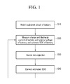
- FIG. 1 is a flowchart illustrating a method for estimating a state of charge (SOC) of a battery according to an exemplary embodiment of the principles of the present invention.
- the method for estimating the SOC of the battery uses an adaptive filter and a data rejection method.
- the battery including at least two packs having a plurality of cells is modeled using an equivalent circuit (Step 10).
- a charging and discharging current of the battery, a battery terminal voltage, and a battery temperature are measured, and the SOC of the battery is estimated (Step 20).
- the data rejection is decided using the measured charging and discharging current of the battery and the estimated SOC of the battery (Step 30).
- the equivalent circuit of the battery modeled in Step 10 is set as a measurement model, and a gain corresponding to a variance of an error generated from the measurement model is generated.
- the estimated SOC of Step 20 is corrected using the gain generated in Step 30 corresponding to the variance of the error of the measurement model (Step 40).
- the correction of the estimated SOC is performed using an adaptive filter, particularly, using a Kalman filter.
- Kalman gain is generated using the gain generated in Step 30 corresponding to the variance of the error of the measurement model, and the SOC estimated in Step 20 is corrected using the generated Kalman gain.
- Step 20 the SOC of the battery is again estimated using the corrected SOC and the charging and discharging current of the battery.
- FIG. 2 is a schematic diagram illustrating the electric vehicle system using the method for estimating the SOC of the battery according to an exemplary embodiment of the principles of the present invention.
- the vehicle system includes a battery management system (BMS) 1, a battery 2, an electric current sensor 3, a cooling fan 4, a fuse 5, a main switch 6, an engine controller unit (ECU) 7, an inverter 8, and a motor generator 9.
- BMS battery management system
- ECU engine controller unit
- Battery 2 includes a plurality of sub-packs 2a to 2h in which a plurality of battery cells are coupled in series, output terminals 2_OUT1 and 2_OUT2, and a safety switch 2_SW provided between sub-pack 2d and sub-pack 2e.
- Sub-packs 2a to 2h are exemplarily provided in a number of eight, and each sub-pack is exemplarily illustrated to merely indicate the plurality of battery cells by one group, and is not intended to limit a scope of the present invention.
- Safety switch 2_SW refers to a switch provided between sub-pack 2d and sub-pack 2e. Safety switch 2_SW can be manually switched on/off for the sake of worker's safety when the battery is replaced or a work is executed for the battery.
- safety switch 2_SW is provided between sub-pack 2d and sub-pack 2e, but it is not intended to limit a scope of the present invention.
- Both output terminal 2_OUT1 and output terminal 2_OUT2 connect to inverter 8.
- Electric current sensor 3 measures an amount of electric current outputted from battery 2, and outputs the measured current amount to a sensor 10 of BMS 1.
- Electric current sensor 3 can be a Hall current transformer (CT) for measuring the current by using a Hall device, and outputting an analog current signal associated with the measured current.
- CT Hall current transformer
- Cooling fan 4 dissipates a heat generated during the charge and discharge of battery 2 on the basis of a control signal of BMS 1, thereby preventing battery 2 from being degenerated due to an increase of temperature, and preventing an efficiency of the charge and discharge from being reduced.
- Fuse 5 either disconnects or short-circuits battery 2, thereby preventing an overcurrent from being transmitted to battery 2. In other words, when the overcurrent is generated, fuse 5 disconnects battery 2, thereby preventing the overcurrent from being transmitted to battery 2.
- main switch 6 switches off battery 2 on the basis of the control signal of BMS 1 or ECU 7 of the vehicle.
- BMS 1 includes sensor 10, a main control unit (MCU) 20, an internal power supplying unit 30, a cell balancing unit 40, a storage unit 50, a communication unit 60, a protective circuit 70, a power-on reset unit 80, and an external interface 90.
- MCU main control unit
- Sensor 10 senses and transmits the battery charging and discharging current, the battery terminal voltage, the voltage across each cell, a cell temperature, and a peripheral temperature, to MCU 20.
- MCU 20 generates information for estimating the SOC and a state of health (SOH) of battery 2 on the basis of the battery charging and discharging current, the battery terminal voltage, each cell voltage, the cell temperature, and the peripheral temperature received from sensor 10, and for informing a state of battery 2, and transmits the generated information to ECU 7 of the vehicle.
- ECU 7 of the vehicle charges and discharge battery 2 on the basis of the SOC and the SOH received from MCU 20.
- MCU 20 uses a method for modeling the battery by the equivalent circuit, predicting the SOC to be estimated, and correcting the predicted SOC.
- the equivalent circuit modeling the battery is set as the measurement model, and uses the data rejection method to correct the predicted SOC in consideration of the variance of the error generated from the measurement model. A detailed description will be made with reference to FIGS. 3 to 5 below.
- Internal power supplying unit 30 supplies a power source to BMS 1 using a sub battery.
- Cell balancing unit 40 balances the state of charge of each cell. In other words, cell balancing unit 40 can discharge a cell of a relatively high charged state, and can charge a cell of a relatively low charged state.
- Storage unit 50 stores data of the SOC and SOH when BMS 1 is powered off.
- Storage unit 50 can be a nonvolatile storage unit that is an electrically erasable programmable read only memory (EEPROM).
- Communication unit 60 communicates with ECU 7 of the vehicle.
- Protective circuit 70 protects battery 2 from external impact, overcurrent, and low voltage, using a firmware.
- Power-on reset unit 80 resets an entire system when BMS 1 is powered on.
- External interface 90 connects sub devices of BMS 1, such as cooling fan 4 and main switch 6, to MCU 20. In the exemplary embodiment of the present invention illustrated in FIG. 2, only cooling fan 4 and main switch 6 are shown but are not intended to limit a scope
- ECU 7 determines a degree of a torque of the vehicle on the basis of the information of a component of the vehicle, such as an accelerator, a brake, and a speed of the vehicle, and controls motor generator 9 to have an output based on torque information. In other words, ECU 7 controls the switching of inverter 8, and controls motor generator 9 to have the output based on the torque information. ECU 7 receives the SOC of battery 2 from MCU 20 through communication unit 60 of BMS 1, and controls the SOC of battery 2 to reach a target value (e.g., 55%).
- a target value e.g., 55%).
- ECU 7 For example, if ECU 7 receives the SOC of 55% or less from MCU 20, ECU 7 controls a switch of inverter 8 to output a power toward battery 2, thereby charging battery 2; if ECU 7 receives the SOC of 55% or more, ECU 7 controls the switch of inverter 8 to output the power toward motor generator 9, thereby discharging battery 2.
- Inverter 8 enables battery 2 to be charged or discharged on the basis of the control signal of ECU 7.
- Motor generator 9 drives the vehicle on the basis of the torque information received from the ECU 7, using the electrical energy of battery 2.
- ECU 7 charges and discharges battery 2 as much as a rechargeable power on the basis of the SOC, thereby preventing battery 2 from being overcharged and overdischarged and making it possible to efficiently use battery 2 for a long time.
- BMS 1 should accurately estimate the SOC, using the pack current and the pack voltage sensed in sensor 10, and transmit the estimated SOC to ECU 7.
- BMS 1 according to an exemplary embodiment of the present invention will be described with reference to FIGS. 3 to 5 below.
- FIG. 3 is the equivalent circuit of the battery according to an exemplary embodiment of the present invention.
- the equivalent circuit of the battery includes a diffusion impedance, an internal resistance R i , and the OCV.
- the diffusion impedance can be expressed using a resistor R diff and a capacitor C diff
- the OCV can be expressed using a function of the SOC.
- resistor R diff and capacitor C diff are set unchanged as a function of an external element like the SOC, the temperature, and the charging and discharging current i flowing through the battery.
- Internal resistance R i varies as a function of the battery temperature like the cell temperature or the ambient temperature of the cell. A relationship between the internal resistance and the temperature is established by an experiment method.
- Error caused by the variation of resistor R diff and capacitor C diff can be corrected using the data rejection method based on the error variance.
- the data rejection method will be described later in detail.
- the equivalent circuit of the battery according to an exemplary embodiment of the present invention will be briefly described by the measurement model below.
- MCU 20 according to an exemplary embodiment of the present invention will be in detail described with reference to FIG. 4 below.
- FIG. 4 is a diagram illustrating MCU 20 according to an exemplary embodiment of the present invention.
- MCU 20 includes a predictor 21, a measurement unit 22, and a data rejection unit 23.
- Predictor 21 predicts a parameter for indicating the state of the battery using the ampere counting method.
- the SOC and capacitance C diff of the diffusion impedance Z diff are provided as the parameter for indicating the state.
- Predictor 21 receives the charging and discharging current i flowing through the battery from sensor 10, performs the measurement using the ampere counting method, and predicts the SOC that is a present state of the battery.
- Predictor 21 predicts a voltage V diff applied between both terminals of the diffusion impedance Z diff by using the charging and discharging current i flowing through the battery.
- measurement unit 22 corrects the predicted parameters to indicate the battery state by using a measurable parameter associated with a state to be estimated.
- Measurement unit 22 receives battery terminal voltage V t measured by sensor 10 in the measurement model, calculates the SOC predicted in predictor 21 and the OCV associated with temperature T that is received from sensor 10, calculates a voltage V r applied across internal resistance R i by using the internal resistance and the charging and discharging current i received form sensor 10, estimates the battery terminal voltage V t by using the calculated OCV and voltage V r and diffusion impedance voltage V diff predicted in predictor 21, compares the estimated battery terminal voltage V t with the measured battery terminal voltage V t , and corrects the predicted SOC and the like on the basis of the comparison result.
- Data rejection unit 23 controls measurement unit 22 to correct the predicted parameters of the battery considering the variance of the error generated from the measurement model.
- MCU 20 stores information of the variance of the error generated from the measurement model as a function of the SOC of the battery, the charging and discharging current flowing through the battery, the temperature, and a dynamic of the current.
- MCU 20 can further include a database (not shown) for constructing and storing the information by a data table. The information can be generated in the experiment method.
- Data rejection unit 23 detects the variance of the measurement error as a function of the present state from the data table by using the data table, and transmits the detected error variance to measurement unit 22.
- Measurement unit 22 decides a degree of correction of the predicted parameter of the battery as a function of the detected error variance.
- the battery management system in which a prediction is performed, a prediction error is corrected using the adaptive filter, the SOC of the battery is estimated, and the error generated between an actual battery and the measurement model of the battery is prevented using the data rejection method, will be described below.
- Predictor 21 and estimator (i.e., measurement unit) 22 of MCU 20 employ algorithm that is similar with an extended Kalman filter (EKF), a kind of the adaptive filter.
- EKF extended Kalman filter
- Predictor 21 predicts state variables x, which are the SOC of the battery and voltage V Diff applied across the diffusion impedance, using a state equation (a) in Equation 1.
- Predictor 21 uses a nonlinear matrix equation (b) as a state equation (a) in Equation 1. In equation (b), the ampere counting is performed for a certain time, and the SOC and voltage V Diff are discretely predicted.
- SOC K and V DiffK correspond to state variable X k ( - ) .
- SOC K denotes a SOC predicted in the present state
- SOC K-1 denotes a value obtained by correcting a SOC predicted in an earlier state and correcting an error in measurement unit 22.
- V DiffK denotes voltage V Diff applied to the diffusion impedance of the present state
- V DiffK- 1 denotes a value obtained by correcting voltage V Diff applied to the diffusion impedance predicted in the earlier state, and correcting the error in measurement unit 22.
- C Diff and R Diff denote the capacitance and the resistance of the diffusion impedance, respectively.
- Predictor 21 estimates the SOC by a discrete time, and ⁇ t is a temporal interval between the present state and earlier state.
- i K-1 denotes the electric current flowing through the battery in the earlier state.
- C n denotes a constant value corresponding to a rating capacitance of the battery, and does not vary as a function of the state.
- 1 0 0 1 - ⁇ ⁇ t C Diff ⁇ R Diff corresponds to f k -1 in Equation 1(a).
- ⁇ ⁇ t C n ⁇ ⁇ t C Diff ⁇ i K - 1 corresponds to W k- 1 in Equation 1(a), and is inputted in each state.
- Predictor 21 predicts a covariance P k (-) for the estimation error of state variable x on a per-discrete time basis, using Equation 2, and transmits predicted covariance P k (-) to measurement unit 22.
- P k - A k - 1 1 ⁇ P k - 1 + ⁇ A k - 1 [ 1 ] T + Q k - 1 , A k - 1 1 ⁇ ⁇ f k ⁇ x ⁇
- x x ⁇ k - 1 -
- a k - 1 1 denotes a value obtained by differentiating and linearizing nonlinear matrix equation f k -1 by the state variable, and Q k denotes a variance value of the state variable based on each state.
- Predictor 21 generates and transmits the predicted state variable x ⁇ k (-), and covariance P k (-) for the estimation of the error of the state variable, to measurement unit 22.
- Vr denotes a voltage drop occurring when current i flows through internal resistor Ri .
- Measurement unit 22 uses a differential equation like Equation 4, for generating a Kalman gain to solve a nonlinearity between the SOC and the OCV and use the Kalman filter.
- Equation 4 can define the OCV as the function of the SOC, and equation 4 is of a type in which the output equation is differentiated by the state variable (SOC).
- Measurement unit 22 generates Kalman gain to correct the predicted SOC and voltage Vdiff. Equation 5 is to calculate the Kalman gain.
- K ⁇ k P k - ⁇ H k [ 1 ] T [ H k 1 ⁇ P k - ⁇ H k [ 1 ] T + R k ⁇ ] - 1 , H k 1 ⁇ ⁇ h k ⁇ x ⁇
- x x ⁇ k -
- H k 1 denotes Equation 4 showing a differential matrix to linearize a function of predicted state variable x and output variable y.
- H k 1 ⁇ T denotes an inverse matrix of H k 1
- R k denotes the variance of the error generated from the measurement model.
- R k can be set as a function of the SOC, an intensity of the electric current, the temperature, and the dynamic of the electric current.
- Measurement unit 22 can detect and use R k corresponding to at least two elements among the SOC, the intensity of the electric current, the temperature, and the dynamic of the electric current.
- Measurement unit 22 corrects the predicted state variable x, using the generated Kalman gain, as in Equation 6.
- x ⁇ k + x ⁇ k - + K ⁇ k ⁇ z k - z ⁇ k
- Variable x corresponds to the SOC and voltage V Diff
- variable z corresponds to battery terminal voltage V t
- x ⁇ k (+) denotes variable x obtained by error correcting the predicted SOC by using the Kalman gain
- x ⁇ k (-) denotes variable x predicted in predictor 21
- z k denotes an average of battery terminal voltage V t
- ⁇ k denotes battery terminal voltage V t currently measured in the measurement model.
- Measurement unit 22 generates covariance P k (+) for the estimation of the error of corrected state variable x ⁇ k (+), using the Kalman gain, as in Equation 7.
- P k + I - K ⁇ k ⁇ H k 1 ⁇ P k -
- P k (+) denotes the covariance for the estimation error of each of the corrected SOC and the corrected voltage V Diff that are state variable x ⁇ k (+) .
- Measurement unit 22 corrects predicted SOC (i.e., x ⁇ k (-)) and covariance P k (-) using the Kalman gain, and generates SOC (i.e., x ⁇ k (+)) and covariance P k (+) .
- SOC (i.e., x ⁇ k (+)) and covariance P k (+) are transmitted to predictor 21, and are set as initial values for predicting a next state.
- measurement unit 22 generates and transmits corrected voltage V Diff and covariance even for predicted voltage V Diff , to predictor 21. Then, they are set as initial values for predicting the next state.
- Data rejection unit 23 detects variance R k of the error of the measurement model corresponding to the present state, from the data table, corrects the error variance R k as a function of the present state, and transmits the corrected variance R k to measurement unit 22.
- data rejection unit 23 uses the variance of the error caused by an inaccuracy of the measurement model in deciding how much it corrects the predicted state using the measurement model.
- the Kalman gain varies as a function of error variance R k
- error variance R k is decided as a function of the error of the measurement model. Accordingly, the Kalman gain is decided as a function of the error generated from the measurement model, and the prediction SOC is corrected as in Equation 6.
- data rejection unit 23 sets a reliable section and an unreliable section for temperature T, SOC, the dynamic of the electric current, and the intensity of the electric current, and controls error variance R k as a function of the section.
- Temperature T can be received from the sensor, and the SOC can use the information received from predictor 21. They are not intended, however, to limit a scope of the present invention.
- Variance R k is fixed as a preset constant value in the reliable section, and is changed by data rejection unit 23 in the unreliable section.
- the battery cell temperature or the cell peripheral temperature is detected.
- error variance R k is fixed as the preset value, and the Kalman gain is generated.
- error variance R k is changed using a relationship between the temperature and error variance R k through the experiment, and the Kalman gain is generated.
- the battery has a complex measurement model due to diffusion at both terminals of the SOC and other complicated elements. Therefore, the measurement model can be also differently constructed on a per-SOC region basis. This, however, makes a process of estimating the SOC complex. Therefore, as described above, MCU 20 uses the measurement model having the equivalent circuit of FIG. 2, and uses the error generated from the measurement model, thereby determining a degree of data rejection and estimating the SOC.
- FIG. 6 shows a graph illustrating an impedance of the measurement model on a per-SOC region basis.
- the impedance follows an impedance curve different from those of other SOC regions, although the difference depends on the OCV.
- Equation 8 R k denotes the error variance controlled as a function of the present state, and R k -1 denotes the error variance in the earlier state.
- G SOC denotes a variable for deciding a data rejection effect, and is measured through the experiment. According to an exemplary embodiment of the present invention, G SOC is equal to "10".
- the accuracy of estimating the SOC of the battery can be varied as a function of the current flowing through the battery, that is, the intensity of the charging and discharging current. This happens due to not only a nonlinear characteristic of the battery but also the error generated from the measurement model.
- FIG. 7 shows a graph illustrating a relationship between the SOC and a total resistance of the battery as a function of the intensity of the discharge current of the battery.
- R k denotes the error variance controlled as a function of the present state
- R k -1 denotes the error variance in the earlier state
- G i denotes a constant value obtained through experiment, and G i is equal to "2" in an exemplary embodiment of the present invention.
- the accuracy of estimating the SOC of the battery can be varied as a function of the dynamic of the charging and discharging current.
- the dynamic of the electric current refers to an amount of variation of the electric current dependent on time. In other words, the dynamic of the current is large when the variation of the current per unitary time is large, and the dynamic of the current is small when the variation of the current per unitary time is small.
- a capacitor component is simplified and modeled, and the error occurs when the dynamic of the current is generated.
- FIG. 8 shows a graph illustrating a degree of the error generated as a function of the dynamic of the current.
- R k denotes a variance of an error controlled as a function of a present state
- R k -1 denotes a variance of an error in an earlier state
- T steptime denotes a period for varying the current
- G step denotes a constant obtained through experiment.
- a driving method of the BMS using the method for estimating the SOC of the battery according to an exemplary embodiment of the principles of the present invention will be described with reference to FIG. 5.
- FIG. 5 is a flowchart illustrating the driving method of the BMS according to an exemplary embodiment of the present invention.
- Sensor 10 measures the charging and discharging current i and battery terminal voltage Vt , and transmits the measured charging and discharging current i and battery terminal voltage Vt to MCU 20 (Step 100).
- Predictor 21 generates the prediction SOC and prediction voltage V diff , using the charging and discharging current received from sensor 10 (Step 200).
- Data rejection unit 23 receives the prediction SOC from predictor 21, and determines whether or not the prediction SOC is in the reliable section (Step 300). When the prediction SOC is out of the reliable section, data rejection unit 23 changes error variance R k using Equation 8 (Step 310).
- Data rejection unit 23 temporarily stores error variance R k when it is determined that the SOC is in the reliable section in Step 300, and temporarily stores changed variance R k when error variance R k is changed (Step 320).
- data rejection unit 23 determines whether or not the intensity of the charging and discharging current is in the reliable section (Step 400). When it is determined that the intensity of the charging and discharging current is out of the reliable section, data rejection unit 23 changes error variance R k using Equation 9 (Step 410). Data rejection unit 23 temporarily stores error variance R k (S410).
- Data rejection unit 23 temporarily stores error variance R k when it is determined that the intensity of the charging and discharging current is in the reliable section in Step 400, and temporarily stores changed variance R k when error variance R k is changed (Step 420).
- Data rejection unit 23 determines whether or not the dynamic of the charging and discharging current is sensed (Step 500). When it is determined that the dynamic of the charging and discharging current is sensed in Step 500, data rejection unit 23 changes error variance R k using Equation 10 (Step 510).
- Data rejection unit 23 temporarily stores error variance R k when it is determined that the dynamic of the charging and discharging current is not sensed in Step 500, and temporarily stores changed variance R k when error variance R k is changed (Step 520).
- Data rejection unit 23 transmits stored error variance R k to measurement unit 22 (Step 600).
- Measurement unit 22 generates the Kalman gain using the received error variance R k (Step 610). Measurement unit 22 corrects the prediction SOC, prediction voltage V diff , and the covariance as a function of the generated Kalman gain, and transmits the prediction SOC, prediction voltage V diff , and the covariance to be transmitted predictor 21 (Step 620).
- Predictor 21 receives and uses the corrected SOC and voltage V diff to predict a next state. Predictor 21 generates the prediction SOC and voltage V diff of the present state, using the charging and discharging current and the battery terminal voltage received from the sensor in the present state and the SOC and the voltage V diff corrected in the earlier state. The above process is repeated.
- the state of the battery is estimated considering the error of the measurement model using the data rejection method. Accordingly, the battery state, that is, the SOC more accurate than in a contemporary art can be estimated.
- the battery is modeled using a complex model, and its SOC is estimated, there is a disadvantage in which it needs a complex calculation.
- calculation can be reduced, and the accuracy of the SOC estimated using the data rejection method can be improved.
- error variance R k is set correspondingly to the SOC, the dynamic of the current, and the intensity of the current. But, variance R k of the error caused by the temperature can be set. Error variance R k can be set considering at least one of the temperature, the current dynamic, and the current intensity.
- the present invention provides the method for estimating the SOC of the battery using the data rejection method and adaptive filter methods.
- the present invention provides the battery management system and the driving method thereof, for estimating the state of the battery using the data rejection method and adaptive filter methods.
- the present invention provides the method for estimating the SOC, the battery rejection system, and the driving method thereof, for reducing the calculation using the simple battery model, and estimating more accurate SOC using the data rejection method.
- the present invention provides the battery management system and the driving method thereof, for estimating the more accurate SOC considering the variance of the error of the measurement model.
Landscapes
- Engineering & Computer Science (AREA)
- Power Engineering (AREA)
- Physics & Mathematics (AREA)
- General Physics & Mathematics (AREA)
- Life Sciences & Earth Sciences (AREA)
- Sustainable Development (AREA)
- Sustainable Energy (AREA)
- Transportation (AREA)
- Mechanical Engineering (AREA)
- Secondary Cells (AREA)
- Tests Of Electric Status Of Batteries (AREA)
Applications Claiming Priority (1)
| Application Number | Priority Date | Filing Date | Title |
|---|---|---|---|
| KR1020060057521A KR100804698B1 (ko) | 2006-06-26 | 2006-06-26 | 배터리 soc 추정 방법 및 이를 이용하는 배터리 관리시스템 및 구동 방법 |
Publications (2)
| Publication Number | Publication Date |
|---|---|
| EP1873542A1 true EP1873542A1 (fr) | 2008-01-02 |
| EP1873542B1 EP1873542B1 (fr) | 2010-09-01 |
Family
ID=38446048
Family Applications (1)
| Application Number | Title | Priority Date | Filing Date |
|---|---|---|---|
| EP07111015A Active EP1873542B1 (fr) | 2006-06-26 | 2007-06-26 | Appareil et méthode pour évaluer l'état de charge d'une pile |
Country Status (6)
| Country | Link |
|---|---|
| US (1) | US8008891B2 (fr) |
| EP (1) | EP1873542B1 (fr) |
| JP (1) | JP5074830B2 (fr) |
| KR (1) | KR100804698B1 (fr) |
| CN (1) | CN100547849C (fr) |
| DE (1) | DE602007008793D1 (fr) |
Cited By (18)
| Publication number | Priority date | Publication date | Assignee | Title |
|---|---|---|---|---|
| EP2001074A1 (fr) * | 2007-06-07 | 2008-12-10 | Peugeot Citroen Automobiles SA | Système et procédé de détermination de la perte de capacité et de l'énergie d'une batterie |
| WO2010029355A3 (fr) * | 2008-09-09 | 2010-05-06 | Ricardo Uk Limited | Estimation de l’état de charge |
| FR2941053A1 (fr) * | 2009-01-15 | 2010-07-16 | Peugeot Citroen Automobiles Sa | Dispositif et procede d'estimation rapide de l'etat de charge d'une batterie d'un engin a moteur, a partir d'equations non lineaires |
| EP2400313A1 (fr) * | 2010-06-17 | 2011-12-28 | Volvo Car Corporation | Procédé et agencement pour assurer une alimentation électrique suffisante pour différents systèmes de véhicules électriques |
| CN102590749A (zh) * | 2011-01-14 | 2012-07-18 | 朴昌浩 | 一种电池荷电状态预测内核设计方法 |
| FR2975501A1 (fr) * | 2011-05-20 | 2012-11-23 | Renault Sas | Procede d'estimation de l'etat de charge d'une batterie electrique |
| US8751086B2 (en) | 2012-08-21 | 2014-06-10 | Ford Global Technologies, Llc | Online battery capacity estimation |
| US8901892B2 (en) | 2005-08-03 | 2014-12-02 | California Institute Of Technology | Methods and systems for thermodynamic evaluation of battery state of health |
| US9065292B2 (en) | 2010-08-23 | 2015-06-23 | California Institute Of Technology | Methods and systems for charging electrochemical cells |
| EP2700966A4 (fr) * | 2012-03-16 | 2015-11-11 | Lg Chemical Ltd | Dispositif et procédé d'estimation de l'état d'une batterie |
| WO2015180743A1 (fr) * | 2014-05-28 | 2015-12-03 | Volvo Truck Corporation | Procédé pour déterminer la fiabilité de valeurs de paramètres d'état de santé |
| EP3045925A1 (fr) * | 2015-01-14 | 2016-07-20 | Corvus Energy Ltd. | Procédé et système pour déterminer un état de charge de manière itérative d'une cellule de batterie |
| US10556510B2 (en) | 2012-04-27 | 2020-02-11 | California Institute Of Technology | Accurate assessment of the state of charge of electrochemical cells |
| EP3588115A4 (fr) * | 2017-09-07 | 2020-04-29 | LG Chem, Ltd. | Dispositif et procédé pour estimer l'état de charge d'une batterie |
| EP3745151A1 (fr) * | 2019-05-24 | 2020-12-02 | Contemporary Amperex Technology Co., Limited | Procédé et appareil pour la correction de l'état de charge, système de gestion de batterie et support d'enregistrement |
| EP3565731B1 (fr) | 2017-01-09 | 2022-10-19 | Volvo Truck Corporation | Procédé et configuration de détermination de l'état de charge d'un bloc-batterie |
| JP2022549136A (ja) * | 2019-09-30 | 2022-11-24 | ルノー エス.ア.エス. | 電気自動車またはハイブリッド自動車内の高電圧回路の絶縁抵抗を推定するための方法 |
| DE102015107930B4 (de) | 2014-06-09 | 2023-05-17 | Ford Global Technologies, Llc | Schätzung und Ausgleich von Batteriemessungen |
Families Citing this family (154)
| Publication number | Priority date | Publication date | Assignee | Title |
|---|---|---|---|---|
| US8103485B2 (en) * | 2004-11-11 | 2012-01-24 | Lg Chem, Ltd. | State and parameter estimation for an electrochemical cell |
| KR100814883B1 (ko) * | 2006-10-16 | 2008-03-20 | 삼성에스디아이 주식회사 | 배터리 관리 시스템 및 그의 구동 방법 |
| KR100916441B1 (ko) | 2007-06-11 | 2009-09-07 | 현대자동차주식회사 | 인버터 스위칭을 이용한 배터리 임피던스 측정 및 이를통한 배터리 충전상태의 추정방법 |
| EP2160616A1 (fr) * | 2007-07-02 | 2010-03-10 | ABB Research LTD | Détermination de l'état de charge |
| KR100928727B1 (ko) * | 2007-12-18 | 2009-11-27 | 자동차부품연구원 | 울트라 커패시터의 잔존용량 산출방법 |
| US7994755B2 (en) | 2008-01-30 | 2011-08-09 | Lg Chem, Ltd. | System, method, and article of manufacture for determining an estimated battery cell module state |
| DE102008009970A1 (de) * | 2008-02-20 | 2009-08-27 | Li-Tec Vermögensverwaltungs GmbH | Batteriemanagementsystem |
| KR100986357B1 (ko) * | 2008-07-15 | 2010-10-08 | 현대자동차주식회사 | 하이브리드 차량의 배터리 잔존용량 추정 방법 |
| KR101187766B1 (ko) | 2008-08-08 | 2012-10-05 | 주식회사 엘지화학 | 배터리 셀의 전압 변화 거동을 이용한 셀 밸런싱 장치 및 방법 |
| KR100927541B1 (ko) * | 2008-08-14 | 2009-11-17 | 주식회사 엘지화학 | 배터리 전압 거동을 이용한 배터리 저항 특성 추정 장치 및방법 |
| JP4649682B2 (ja) * | 2008-09-02 | 2011-03-16 | 株式会社豊田中央研究所 | 二次電池の状態推定装置 |
| JP5349250B2 (ja) * | 2008-12-01 | 2013-11-20 | カルソニックカンセイ株式会社 | 電池モデル同定方法 |
| US8116998B2 (en) | 2009-01-30 | 2012-02-14 | Bae Systems Controls, Inc. | Battery health assessment estimator |
| FR2948771B1 (fr) * | 2009-07-28 | 2011-08-26 | Commissariat Energie Atomique | Procede de caracterisation d'une batterie electrique |
| DE102009045526A1 (de) * | 2009-10-09 | 2011-04-14 | SB LiMotive Company Ltd., Suwon | Verfahren zur Initialisierung und des Betriebs eines Batteriemanagementsystems |
| DE102009049320A1 (de) * | 2009-10-14 | 2011-04-21 | Bayerische Motoren Werke Aktiengesellschaft | Verfahren zur Bestimmung und/oder Vorhersage der Hochstrombelastbarkeit einer Batterie |
| KR101277733B1 (ko) * | 2010-01-27 | 2013-06-24 | 주식회사 엘지화학 | 배터리의 soc를 추정하는 장치 및 방법 |
| EP2562514B1 (fr) * | 2010-04-19 | 2019-02-27 | Nissan Motor Co., Ltd | Dispositif de fourniture d'informations et procédé de fourniture d'informations |
| CN102279365B (zh) * | 2010-06-09 | 2015-09-09 | 南京德朔实业有限公司 | 电动工具控制电路及其操作方法 |
| DE102010038646A1 (de) * | 2010-07-29 | 2012-02-02 | Robert Bosch Gmbh | Verfahren und Anordnung zum Abschätzen der Leistungsfähigkeit mindestens einer Batterieeinheit einer wiederaufladbaren Batterie |
| US20120053871A1 (en) * | 2010-08-31 | 2012-03-01 | Michael Sirard | Integrated Intelligent Battery Management System and Monitoring System |
| AU2011316798B2 (en) | 2010-10-22 | 2017-02-02 | Nucleus Scientific, Inc. | Apparatus and method for rapidly charging batteries |
| US8525519B2 (en) * | 2010-11-30 | 2013-09-03 | GM Global Technology Operations LLC | Algorithm for determining the capacity of a battery while in service |
| TW201224485A (en) | 2010-12-02 | 2012-06-16 | Ind Tech Res Inst | State-of-charge estimation method and battery control unit |
| CN102540081B (zh) * | 2010-12-29 | 2015-01-21 | 上海汽车集团股份有限公司 | 用于确定车载蓄电池荷电状态的方法 |
| KR101238478B1 (ko) * | 2011-01-16 | 2013-03-04 | 김득수 | 배터리 잔존 용량 측정 방법 |
| JP5616464B2 (ja) * | 2011-01-17 | 2014-10-29 | プライムアースEvエナジー株式会社 | 二次電池の充電状態推定装置 |
| US20130030738A1 (en) * | 2011-01-19 | 2013-01-31 | Sendyne Corporation | Converging algorithm for real-time battery prediction |
| US20120203421A1 (en) * | 2011-02-07 | 2012-08-09 | GM Global Technology Operations LLC | Data association for vehicles |
| KR101201811B1 (ko) * | 2011-03-15 | 2012-11-15 | 삼성에스디아이 주식회사 | 충방전 장치 |
| DE102011007884A1 (de) * | 2011-04-21 | 2012-10-25 | Sb Limotive Company Ltd. | Verfahren zur Bestimmung eines maximal verfügbaren Konstantstroms einer Batterie |
| US8449998B2 (en) | 2011-04-25 | 2013-05-28 | Lg Chem, Ltd. | Battery system and method for increasing an operational life of a battery cell |
| KR20120134415A (ko) * | 2011-06-02 | 2012-12-12 | 에스케이이노베이션 주식회사 | Ess의 배터리 수명 예측 시스템 및 그 방법 |
| US10234512B2 (en) | 2011-06-11 | 2019-03-19 | Sendyne Corporation | Current-based cell modeling |
| US8706333B2 (en) * | 2011-06-28 | 2014-04-22 | Ford Global Technologies, Llc | Nonlinear observer for battery state of charge estimation |
| US8880253B2 (en) | 2011-06-28 | 2014-11-04 | Ford Global Technologies, Llc | Nonlinear adaptive observation approach to battery state of charge estimation |
| CN102861726B (zh) * | 2011-07-05 | 2014-07-30 | 广州丰江电池新技术股份有限公司 | 一种锂二次电池一致性筛选方法 |
| JP5595361B2 (ja) * | 2011-09-27 | 2014-09-24 | プライムアースEvエナジー株式会社 | 二次電池の充電状態推定装置 |
| US20140232411A1 (en) * | 2011-09-30 | 2014-08-21 | KPIT Cummins Infosytems Ltd | System and method for battery monitoring |
| US8918300B2 (en) * | 2011-10-07 | 2014-12-23 | Calsonic Kansei Corporation | Apparatus and method for battery state of charge estimation |
| US9157966B2 (en) * | 2011-11-25 | 2015-10-13 | Honeywell International Inc. | Method and apparatus for online determination of battery state of charge and state of health |
| DE102012202077A1 (de) * | 2012-02-13 | 2013-08-14 | Robert Bosch Gmbh | Verfahren zum Bestimmen eines Stroms, Batteriemanagementeinheit, Batterie und Kraftfahrzeug |
| JP5798067B2 (ja) | 2012-03-13 | 2015-10-21 | プライムアースEvエナジー株式会社 | 二次電池の状態推定装置 |
| JP6040724B2 (ja) * | 2012-03-13 | 2016-12-07 | 日産自動車株式会社 | バッテリの残存容量算出装置及びバッテリの残存容量算出方法 |
| CN102608542B (zh) * | 2012-04-10 | 2013-12-11 | 吉林大学 | 动力电池荷电状态估计方法 |
| JP5783122B2 (ja) * | 2012-04-11 | 2015-09-24 | トヨタ自動車株式会社 | 電池状態推定装置 |
| CN104471415B (zh) * | 2012-04-27 | 2017-09-01 | 加州理工学院 | 用于电池应用的嵌入式芯片 |
| US8890484B2 (en) * | 2012-05-08 | 2014-11-18 | GM Global Technology Operations LLC | Battery state-of-charge estimator using robust H∞ observer |
| DE102012207806A1 (de) * | 2012-05-10 | 2013-11-14 | Robert Bosch Gmbh | Verfahren zum Betreiben eines Batteriesystems, Batteriesystem und Kraftfahrzeug |
| US9869725B2 (en) * | 2012-05-16 | 2018-01-16 | Robert Bosch Gmbh | Battery system and method with capacity estimator |
| CN102721933A (zh) * | 2012-06-29 | 2012-10-10 | 国家电网公司 | 一种锂离子电池的soc估算方法和系统 |
| US20140095089A1 (en) * | 2012-10-02 | 2014-04-03 | Zhijian James Wu | System and method for estimated battery state of charge |
| JP5944291B2 (ja) * | 2012-10-05 | 2016-07-05 | カルソニックカンセイ株式会社 | バッテリのパラメータ等推定装置およびその推定方法 |
| US9658291B1 (en) * | 2012-10-06 | 2017-05-23 | Hrl Laboratories, Llc | Methods and apparatus for dynamic estimation of battery open-circuit voltage |
| KR101398465B1 (ko) * | 2012-11-23 | 2014-05-27 | 한국기술교육대학교 산학협력단 | 배터리 상태 판단 장치 및 그 판단 방법 |
| DE102012224060A1 (de) * | 2012-12-20 | 2014-06-26 | Robert Bosch Gmbh | Verfahren zur Datenübertragung für ein Batteriemanagementsystem |
| US9417270B2 (en) | 2013-01-08 | 2016-08-16 | GM Global Technology Operations LLC | Systems and methods to capture and utilize temperature information in a battery system |
| CN103077291B (zh) * | 2013-01-25 | 2016-05-18 | 华北电力大学 | 可设置初始荷电状态的电池充放电过程数字仿真方法 |
| US8935043B2 (en) * | 2013-01-29 | 2015-01-13 | Ford Global Technologies, Llc | Temperature compensated battery parameter estimation |
| US9244129B2 (en) * | 2013-01-29 | 2016-01-26 | Mitsubishi Electronic Research Laboratories, Inc. | Method for estimating a state of charge of batteries |
| US10664562B2 (en) * | 2013-02-24 | 2020-05-26 | Fairchild Semiconductor Corporation and University of Connecticut | Battery state of charge tracking, equivalent circuit selection and benchmarking |
| CN104007390B (zh) * | 2013-02-24 | 2018-03-20 | 快捷半导体(苏州)有限公司 | 电池电荷状态跟踪、等效电路选择及基准测试方法及系统 |
| CN103197251B (zh) * | 2013-02-27 | 2016-02-03 | 山东省科学院自动化研究所 | 一种动力锂电池二阶rc等效模型的辨识方法 |
| US20140272653A1 (en) * | 2013-03-14 | 2014-09-18 | Robert Bosch Gmbh | Flow Battery System and Method of SOC Determination |
| WO2014191794A1 (fr) * | 2013-05-29 | 2014-12-04 | Freescale Semiconductor, Inc. | Appareil de surveillance de cellules, appareil de surveillance de batterie, circuit intégré et procédé permettant de surveiller une cellule rechargeable |
| FR3007531B1 (fr) * | 2013-06-25 | 2016-12-30 | Commissariat Energie Atomique | Procede d'evaluation de l'etat de charge d'une batterie |
| CN103401534B (zh) * | 2013-07-24 | 2015-12-23 | 中达电通股份有限公司 | 基于rc电路充放电最终电压快速预测的方法 |
| JP6376777B2 (ja) * | 2013-07-30 | 2018-08-22 | 住友重機械工業株式会社 | 作業機械 |
| EP3033798B1 (fr) * | 2013-08-15 | 2020-01-22 | Robert Bosch GmbH | Système de batterie lithium/métal à température élevée |
| JP6130275B2 (ja) * | 2013-09-05 | 2017-05-17 | カルソニックカンセイ株式会社 | 推定装置及び推定方法 |
| KR102079038B1 (ko) * | 2013-09-30 | 2020-02-19 | 현대모비스 주식회사 | 지능형 배터리 센서 장치 및 그 동작 방법 |
| JP6421411B2 (ja) * | 2013-11-29 | 2018-11-14 | 富士通株式会社 | 電池の充電率を推定する推定プログラム、電池の充電率を推定する推定方法、および、電池の充電率を推定する推定装置 |
| CN104714181B (zh) * | 2013-12-11 | 2017-10-27 | 广州汽车集团股份有限公司 | 一种获取电压与电池荷电状态关系的方法和系统 |
| CN103713264A (zh) * | 2013-12-20 | 2014-04-09 | 中国北方车辆研究所 | 一种电池管理系统soc估算精度测试系统及测试方法 |
| CN103760495A (zh) * | 2014-01-24 | 2014-04-30 | 哈尔滨工业大学 | 一种用于bms检测的soc源产生方法及soc估计精度测试方法 |
| US9539912B2 (en) | 2014-02-20 | 2017-01-10 | Ford Global Technologies, Llc | Battery capacity estimation using state of charge initialization-on-the-fly concept |
| US9381825B2 (en) * | 2014-02-20 | 2016-07-05 | Ford Global Technologies, Llc | State of charge quality based cell balancing control |
| CN104113311A (zh) * | 2014-02-28 | 2014-10-22 | 中国电子科技集团公司第十四研究所 | 一种开关电容型比较器的失调校正电路及其控制方法 |
| JP6213333B2 (ja) * | 2014-03-25 | 2017-10-18 | 富士通株式会社 | 推定プログラム、推定方法および推定装置 |
| JP6221884B2 (ja) * | 2014-03-25 | 2017-11-01 | 富士通株式会社 | 推定プログラム、推定方法および推定装置 |
| FR3019308B1 (fr) * | 2014-03-26 | 2017-08-25 | Renault Sas | Procede d'estimation d'une erreur de mesure de l'intensite du courant traversant une batterie d'accumulateurs |
| US10288691B2 (en) * | 2014-06-05 | 2019-05-14 | Ford Global Technologies, Llc | Method and system for estimating battery model parameters to update battery models used for controls |
| DE102014215849A1 (de) * | 2014-08-11 | 2016-02-11 | Robert Bosch Gmbh | Steuerung und/oder Regelung für eine wenigstens zwei elektrisch in Reihe zueinander schaltbare Batteriezellen aufweisende Sekundärbatterie |
| JP6429994B2 (ja) | 2014-08-14 | 2018-11-28 | シーメンス アクチエンゲゼルシヤフトSiemens Aktiengesellschaft | 熱シールドを備える多機能燃料ノズル |
| US9987942B2 (en) | 2014-09-03 | 2018-06-05 | Ford Global Technologies, Llc | Method of operating vehicle powertrain based on prediction of how different chemical type batteries connected in parallel will operate to output demanded current |
| KR101767635B1 (ko) * | 2014-10-24 | 2017-08-14 | 주식회사 엘지화학 | 이차 전지의 충전 상태 추정 장치 및 그 방법 |
| JP6555773B2 (ja) * | 2014-11-18 | 2019-08-07 | 学校法人立命館 | 蓄電残量推定装置、蓄電池の蓄電残量を推定する方法、及びコンピュータプログラム |
| FR3029297B1 (fr) * | 2014-11-28 | 2016-12-30 | Renault Sa | Procede automatique d'estimation de l'etat de charge d'une cellule d'une batterie |
| KR102335296B1 (ko) | 2014-11-28 | 2021-12-06 | 로베르트 보쉬 게엠베하 | 무선 네트워크 기반 배터리 관리 시스템 |
| FR3029296B1 (fr) * | 2014-11-28 | 2016-12-30 | Renault Sa | Procede automatique d'estimation de l'etat de charge d'une cellule d'une batterie |
| CN104833921B (zh) * | 2014-12-01 | 2017-11-03 | 北京车和家信息技术有限公司 | 电池包荷电状态的计算方法和计算装置 |
| CN104569835B (zh) * | 2014-12-16 | 2017-11-17 | 北京理工大学 | 一种估计电动汽车的动力电池的荷电状态的方法 |
| CN104865536B (zh) * | 2015-06-16 | 2018-01-02 | 天津力神电池股份有限公司 | 一种锂离子电池性能衰减原因的测试及诊断方法 |
| JP6383704B2 (ja) * | 2015-07-02 | 2018-08-29 | 日立オートモティブシステムズ株式会社 | 電池制御装置 |
| JP6274166B2 (ja) * | 2015-08-06 | 2018-02-07 | 株式会社デンソー | 電池温度推定装置 |
| JP6354700B2 (ja) * | 2015-08-07 | 2018-07-11 | 株式会社デンソー | 電池の充電状態推定装置 |
| KR102574257B1 (ko) * | 2015-10-30 | 2023-09-01 | 삼성전자주식회사 | Soh 추정 장치 및 방법과, soh 추정 모델 생성 장치 및 방법 |
| CN105425153B (zh) * | 2015-11-02 | 2017-12-05 | 北京理工大学 | 一种估计电动车辆的动力电池的荷电状态的方法 |
| KR102533878B1 (ko) * | 2015-12-07 | 2023-05-23 | 현대모비스 주식회사 | 배터리 관리 시스템의 측정값 오차 보정 장치 및 그 방법 |
| KR102325681B1 (ko) * | 2015-12-07 | 2021-11-15 | 현대모비스 주식회사 | 배터리 관리 시스템의 측정값 오차 보정 장치 및 그 방법 |
| US10224579B2 (en) | 2015-12-31 | 2019-03-05 | Robert Bosch Gmbh | Evaluating capacity fade in dual insertion batteries using potential and temperature measurements |
| JP6657967B2 (ja) | 2016-01-06 | 2020-03-04 | 株式会社Gsユアサ | 状態推定装置、状態推定方法 |
| JP6830318B2 (ja) * | 2016-01-15 | 2021-02-17 | 株式会社Gsユアサ | 蓄電素子管理装置、蓄電素子モジュール、車両および蓄電素子管理方法 |
| US10686321B2 (en) | 2016-01-29 | 2020-06-16 | Robert Bosch Gmbh | Secondary battery management |
| US10263447B2 (en) * | 2016-01-29 | 2019-04-16 | Robert Bosch Gmbh | Secondary battery management system |
| US10243385B2 (en) | 2016-01-29 | 2019-03-26 | Robert Bosch Gmbh | Secondary battery management system |
| KR101880195B1 (ko) * | 2016-02-05 | 2018-07-20 | 한국과학기술원 | 배터리의 열역학적 정보에 기반한 배터리의 최적 충전 방법 |
| US10040366B2 (en) | 2016-03-10 | 2018-08-07 | Ford Global Technologies, Llc | Battery terminal voltage prediction |
| US10023064B2 (en) | 2016-03-10 | 2018-07-17 | Ford Global Technologies, Llc | Power capability estimation for vehicle battery systems |
| US9960625B2 (en) | 2016-03-31 | 2018-05-01 | Robert Bosch Gmbh | Battery management system with multiple observers |
| US10447046B2 (en) | 2016-09-22 | 2019-10-15 | Robert Bosch Gmbh | Secondary battery management system with remote parameter estimation |
| CN106443480B (zh) * | 2016-11-04 | 2019-11-22 | 天津市捷威动力工业有限公司 | 一种锂离子电池系统soc估算方法 |
| KR102634815B1 (ko) * | 2016-11-22 | 2024-02-07 | 삼성전자주식회사 | 오차 보정에 기초한 배터리 상태 추정 방법 및 장치 |
| KR102035679B1 (ko) * | 2016-11-29 | 2019-10-23 | 주식회사 엘지화학 | 배터리 노화상태 산출 방법 및 시스템 |
| CN106785237B (zh) * | 2016-11-30 | 2023-09-08 | 惠州市蓝微新源技术有限公司 | 一种动力电池热管理方法及系统 |
| CN106786958B (zh) | 2017-01-13 | 2019-06-14 | Oppo广东移动通信有限公司 | 充电方法、装置及终端 |
| KR102179677B1 (ko) | 2017-04-12 | 2020-11-17 | 주식회사 엘지화학 | 노이즈를 반영한 배터리 잔존 용량 산출 장치 및 방법 |
| JP6834757B2 (ja) * | 2017-04-28 | 2021-02-24 | トヨタ自動車株式会社 | 電池システム |
| CN107425563A (zh) * | 2017-06-07 | 2017-12-01 | 南京中感微电子有限公司 | 一种充电电路及电池 |
| WO2019003377A1 (fr) * | 2017-06-29 | 2019-01-03 | 株式会社東芝 | Dispositif d'estimation de quantité restante de batterie d'accumulateurs, procédé d'estimation de quantité restante de batterie d'accumulateurs et programme |
| KR102200550B1 (ko) * | 2017-10-10 | 2021-01-07 | 주식회사 엘지화학 | 이차 전지의 충전 상태를 추정하기 위한 장치 |
| US20190170826A1 (en) * | 2017-12-06 | 2019-06-06 | Cadex Electronics Inc. | Battery state-of-health determination upon charging |
| CN109917298A (zh) * | 2017-12-13 | 2019-06-21 | 北京创昱科技有限公司 | 一种电池荷电状态预测方法和系统 |
| KR102102970B1 (ko) * | 2018-02-12 | 2020-04-21 | 주식회사 알아이파워 | 전기 자전거 제어 장치 및 그 방법 |
| JP7393102B2 (ja) * | 2018-03-16 | 2023-12-06 | 株式会社半導体エネルギー研究所 | 二次電池の異常検出装置 |
| KR102002859B1 (ko) * | 2018-03-26 | 2019-07-23 | 숭실대학교산학협력단 | 배터리 진단 기능을 갖는 충전기 및 그 제어방법 |
| WO2020100707A1 (fr) * | 2018-11-16 | 2020-05-22 | 株式会社Gsユアサ | Dispositif de gestion, procédé de gestion et véhicule |
| EP3828566B1 (fr) * | 2018-12-21 | 2025-02-12 | LG Energy Solution, Ltd. | Procédé pour estimer l'état de charge d'une batterie |
| KR102392399B1 (ko) * | 2018-12-21 | 2022-04-28 | 주식회사 엘지에너지솔루션 | 이차 전지의 스텝 충전 제어 장치 및 방법 |
| KR102465294B1 (ko) * | 2019-01-23 | 2022-11-08 | 주식회사 엘지에너지솔루션 | 배터리 관리 장치, 배터리 관리 방법 및 배터리팩 |
| KR102722271B1 (ko) | 2019-02-07 | 2024-10-24 | 주식회사 엘지에너지솔루션 | 배터리 관리 장치, 배터리 관리 방법 및 배터리팩 |
| KR102757388B1 (ko) * | 2019-02-22 | 2025-01-20 | 주식회사 엘지에너지솔루션 | 배터리 관리 시스템, 배터리 관리 방법, 배터리 팩 및 전기 차량 |
| KR102832250B1 (ko) * | 2019-06-24 | 2025-07-08 | 삼성에스디아이 주식회사 | 이상 배터리 셀 검출 방법 |
| KR102871419B1 (ko) | 2019-10-22 | 2025-10-15 | 삼성전자주식회사 | 배터리 상태 추정 방법 및 장치 |
| CN111044908B (zh) * | 2019-12-24 | 2022-06-14 | 苏州正力新能源科技有限公司 | 一种基于微片段数据和电压滤波的ocv在线计算方法 |
| US11498446B2 (en) * | 2020-01-06 | 2022-11-15 | Ford Global Technologies, Llc | Plug-in charge current management for battery model-based online learning |
| CN111931325B (zh) * | 2020-06-05 | 2024-09-06 | 西安理工大学 | 一种融合环境温度的车用动力电池soc估算方法 |
| DE102020130732A1 (de) | 2020-11-20 | 2022-05-25 | Audi Aktiengesellschaft | Verfahren zum Ermitteln eines Werts eines Parameters einer Batteriezelle, Steuereinrichtung und Kraftfahrzeug |
| KR20220085395A (ko) | 2020-12-15 | 2022-06-22 | 현대자동차주식회사 | 빅데이터를 이용한 차량 배터리 충전 시간 예측 시스템 및 방법 |
| CN115236514B (zh) * | 2021-04-25 | 2025-07-25 | 广汽埃安新能源汽车股份有限公司 | 电池健康状态分析方法及系统、电池管理系统、存储介质 |
| KR102307096B1 (ko) * | 2021-06-11 | 2021-09-30 | 주식회사 메가셀 | 선택적인 정전보상이 가능한 무정전 전원장치 및 정전보상방법 |
| JP7771565B2 (ja) * | 2021-08-26 | 2025-11-18 | 株式会社Gsユアサ | 補正方法、コンピュータプログラム、補正装置及び蓄電デバイス |
| DE102021209542A1 (de) | 2021-08-31 | 2023-03-02 | Robert Bosch Gesellschaft mit beschränkter Haftung | Verfahren zur Bestimmung eines Ladezustands eines elektrischen Energiespeichers, elektrischer Energiespeicher und Vorrichtung |
| CN113917348B (zh) * | 2021-09-29 | 2025-02-14 | 一汽解放汽车有限公司 | 一种电池soc修正方法、装置、计算机设备和存储介质 |
| KR102416009B1 (ko) * | 2022-02-10 | 2022-06-30 | 이중휘 | 배터리의 soc 추정 장치 및 방법 |
| CN114660467B (zh) * | 2022-03-29 | 2023-04-07 | 无锡凌博电子技术股份有限公司 | 一种采用电压动态补偿优化的soc修正方法 |
| CN114883680B (zh) * | 2022-05-26 | 2025-08-19 | 西北工业大学 | 一种锂离子电池温熵系数测量方法 |
| CN115856720A (zh) * | 2022-11-23 | 2023-03-28 | 湖南银杏可靠性技术研究所有限公司 | Bms产品线束接触不良故障在线监测的安全修复方法 |
| KR102666899B1 (ko) | 2023-05-12 | 2024-05-17 | 주식회사 비엘비 | 전압의 특성 변화를 기반으로 하는 배터리 내적 상태 정밀 진단시스템 및 방법 |
| US12344121B2 (en) * | 2023-05-30 | 2025-07-01 | Ford Global Technologies, Llc | Traction battery controller having state-of-charge compensated estimator gain calibration |
| WO2024262783A1 (fr) * | 2023-06-20 | 2024-12-26 | 주식회사 엘지에너지솔루션 | Procédé d'étalonnage pour un état de charge, et système de batterie l'utilisant |
| KR20250038375A (ko) * | 2023-09-12 | 2025-03-19 | 주식회사 엘지에너지솔루션 | 배터리 관리 장치 및 배터리 관리 방법 |
| CN118539572B (zh) * | 2024-07-26 | 2024-11-19 | 浙江艾罗网络能源技术股份有限公司 | 数据处理方法及储能设备 |
| FR3165726A1 (fr) * | 2024-08-26 | 2026-02-27 | Stellantis Auto Sas | Estimation contrôlée de l’état de charge d’une batterie cellulaire d’un système |
Citations (2)
| Publication number | Priority date | Publication date | Assignee | Title |
|---|---|---|---|---|
| US20020036481A1 (en) | 2000-09-25 | 2002-03-28 | Nec Mobile Energy Corporation | Battery pack |
| US20050057255A1 (en) | 2003-09-17 | 2005-03-17 | Tate Edward D. | Generalized electrochemical cell state and parameter estimator |
Family Cites Families (7)
| Publication number | Priority date | Publication date | Assignee | Title |
|---|---|---|---|---|
| US7243945B2 (en) * | 1992-05-05 | 2007-07-17 | Automotive Technologies International, Inc. | Weight measuring systems and methods for vehicles |
| KR100673036B1 (ko) * | 2001-11-09 | 2007-01-22 | 현대중공업 주식회사 | 전기자동차용 전지관리시스템의 배터리 충전상태 추정 방법 |
| JP4228760B2 (ja) * | 2002-07-12 | 2009-02-25 | トヨタ自動車株式会社 | バッテリ充電状態推定装置 |
| US7181572B2 (en) * | 2002-12-02 | 2007-02-20 | Silverbrook Research Pty Ltd | Cache updating method and apparatus |
| JP2006105821A (ja) | 2004-10-06 | 2006-04-20 | Toyota Motor Corp | 二次電池の充電容量推定装置およびその方法 |
| US8103485B2 (en) | 2004-11-11 | 2012-01-24 | Lg Chem, Ltd. | State and parameter estimation for an electrochemical cell |
| JP5058814B2 (ja) * | 2004-11-29 | 2012-10-24 | エルジー・ケム・リミテッド | バッテリーの状態及びパラメーターの推定システム及び方法 |
-
2006
- 2006-06-26 KR KR1020060057521A patent/KR100804698B1/ko active Active
-
2007
- 2007-05-07 US US11/797,766 patent/US8008891B2/en active Active
- 2007-06-01 CN CNB2007101054812A patent/CN100547849C/zh active Active
- 2007-06-08 JP JP2007152766A patent/JP5074830B2/ja active Active
- 2007-06-26 EP EP07111015A patent/EP1873542B1/fr active Active
- 2007-06-26 DE DE602007008793T patent/DE602007008793D1/de active Active
Patent Citations (2)
| Publication number | Priority date | Publication date | Assignee | Title |
|---|---|---|---|---|
| US20020036481A1 (en) | 2000-09-25 | 2002-03-28 | Nec Mobile Energy Corporation | Battery pack |
| US20050057255A1 (en) | 2003-09-17 | 2005-03-17 | Tate Edward D. | Generalized electrochemical cell state and parameter estimator |
Cited By (22)
| Publication number | Priority date | Publication date | Assignee | Title |
|---|---|---|---|---|
| US8901892B2 (en) | 2005-08-03 | 2014-12-02 | California Institute Of Technology | Methods and systems for thermodynamic evaluation of battery state of health |
| EP2001074A1 (fr) * | 2007-06-07 | 2008-12-10 | Peugeot Citroen Automobiles SA | Système et procédé de détermination de la perte de capacité et de l'énergie d'une batterie |
| WO2010029355A3 (fr) * | 2008-09-09 | 2010-05-06 | Ricardo Uk Limited | Estimation de l’état de charge |
| FR2941053A1 (fr) * | 2009-01-15 | 2010-07-16 | Peugeot Citroen Automobiles Sa | Dispositif et procede d'estimation rapide de l'etat de charge d'une batterie d'un engin a moteur, a partir d'equations non lineaires |
| EP2400313A1 (fr) * | 2010-06-17 | 2011-12-28 | Volvo Car Corporation | Procédé et agencement pour assurer une alimentation électrique suffisante pour différents systèmes de véhicules électriques |
| US9065292B2 (en) | 2010-08-23 | 2015-06-23 | California Institute Of Technology | Methods and systems for charging electrochemical cells |
| CN102590749A (zh) * | 2011-01-14 | 2012-07-18 | 朴昌浩 | 一种电池荷电状态预测内核设计方法 |
| CN102590749B (zh) * | 2011-01-14 | 2016-09-28 | 朴昌浩 | 一种电池荷电状态预测内核设计方法 |
| FR2975501A1 (fr) * | 2011-05-20 | 2012-11-23 | Renault Sas | Procede d'estimation de l'etat de charge d'une batterie electrique |
| WO2012160301A1 (fr) * | 2011-05-20 | 2012-11-29 | Renault S.A.S. | Procede d'estimation de l'etat de charge d'une batterie electrique |
| EP2700966A4 (fr) * | 2012-03-16 | 2015-11-11 | Lg Chemical Ltd | Dispositif et procédé d'estimation de l'état d'une batterie |
| US10556510B2 (en) | 2012-04-27 | 2020-02-11 | California Institute Of Technology | Accurate assessment of the state of charge of electrochemical cells |
| US8751086B2 (en) | 2012-08-21 | 2014-06-10 | Ford Global Technologies, Llc | Online battery capacity estimation |
| WO2015180743A1 (fr) * | 2014-05-28 | 2015-12-03 | Volvo Truck Corporation | Procédé pour déterminer la fiabilité de valeurs de paramètres d'état de santé |
| US10365331B2 (en) | 2014-05-28 | 2019-07-30 | Volvo Truck Corporation | Method for determining the reliability of state of health parameter values |
| DE102015107930B4 (de) | 2014-06-09 | 2023-05-17 | Ford Global Technologies, Llc | Schätzung und Ausgleich von Batteriemessungen |
| EP3045925A1 (fr) * | 2015-01-14 | 2016-07-20 | Corvus Energy Ltd. | Procédé et système pour déterminer un état de charge de manière itérative d'une cellule de batterie |
| EP3565731B1 (fr) | 2017-01-09 | 2022-10-19 | Volvo Truck Corporation | Procédé et configuration de détermination de l'état de charge d'un bloc-batterie |
| EP3588115A4 (fr) * | 2017-09-07 | 2020-04-29 | LG Chem, Ltd. | Dispositif et procédé pour estimer l'état de charge d'une batterie |
| EP3745151A1 (fr) * | 2019-05-24 | 2020-12-02 | Contemporary Amperex Technology Co., Limited | Procédé et appareil pour la correction de l'état de charge, système de gestion de batterie et support d'enregistrement |
| US10871521B2 (en) | 2019-05-24 | 2020-12-22 | Contemporary Amperex Technology Co., Limited | Method and apparatus for correcting SOC, battery management system and storage medium |
| JP2022549136A (ja) * | 2019-09-30 | 2022-11-24 | ルノー エス.ア.エス. | 電気自動車またはハイブリッド自動車内の高電圧回路の絶縁抵抗を推定するための方法 |
Also Published As
| Publication number | Publication date |
|---|---|
| CN101098029A (zh) | 2008-01-02 |
| US8008891B2 (en) | 2011-08-30 |
| US20070299620A1 (en) | 2007-12-27 |
| DE602007008793D1 (de) | 2010-10-14 |
| CN100547849C (zh) | 2009-10-07 |
| JP5074830B2 (ja) | 2012-11-14 |
| JP2008010420A (ja) | 2008-01-17 |
| KR100804698B1 (ko) | 2008-02-18 |
| EP1873542B1 (fr) | 2010-09-01 |
| KR20080000160A (ko) | 2008-01-02 |
Similar Documents
| Publication | Publication Date | Title |
|---|---|---|
| EP1873542B1 (fr) | Appareil et méthode pour évaluer l'état de charge d'une pile | |
| EP1897772B1 (fr) | Système de gestion de batterie et son procédé de commande | |
| US7652449B2 (en) | Battery management system and driving method thereof | |
| US5606243A (en) | Battery state judging apparatus | |
| US10955479B2 (en) | Battery control device | |
| EP1801604B1 (fr) | Procédé pour compenser l'état de charge d'une batterie et système de gestion de batterie l'utilisant | |
| EP1777794B1 (fr) | Système de gestion de batterie et méthode pour la détermination de l'état de charge d'une batterie | |
| EP1688754B1 (fr) | Appareil de gestion de batterie | |
| EP2700966B1 (fr) | Dispositif et procédé d'estimation de l'état d'une batterie | |
| EP3410139B1 (fr) | Procédé d'estimation du courant et de l'état de charge d'une batterie ou d'une cellule, sans détection directe du courant dans des conditions de fonctionnement | |
| US7800345B2 (en) | Battery management system and method of operating same | |
| EP2323238A2 (fr) | Procédé de calcul de courant de charge/décharge disponible et dispositif d'alimentation électrique | |
| EP1707974A1 (fr) | Dispositif et procédé de calcul de la capacité résiduelle pour le stockage d'énergie électrique | |
| EP1801947A2 (fr) | Procédé de compensation de l'état de charge d'une batterie et système de gestion de batterie | |
| KR20150019190A (ko) | 배터리 충전 상태 추정 방법 및 이를 위한 장치 | |
| EP3605123B1 (fr) | Dispositif de commande et procédé de commande de batterie rechargeable | |
| EP4194868B1 (fr) | Procédé de prédiction de graphe de tension de décharge et système de batterie l'utilisant | |
| US11125786B2 (en) | Method for detecting an internal short circuit in a first electrical energy storage unit of an electrical energy storage device | |
| US20240174129A1 (en) | Voltage measurement method and operating method for a vehicle on-board power supply system | |
| JP5886225B2 (ja) | 電池制御装置及び電池制御方法 | |
| KR20190102814A (ko) | 배터리 관리 장치 및 방법 | |
| JPH11317243A (ja) | 自動車用電池交換時の容量演算方法 | |
| EP4390416B1 (fr) | Estimation de capacité et d'état de charge pour un système de stockage d'énergie à batteries multiples | |
| KR100749476B1 (ko) | 배터리 관리 시스템 및 그의 구동 방법 | |
| KR101117636B1 (ko) | 배터리의 soc추정 방법 및 이를 이용한 배터리 관리시스템 |
Legal Events
| Date | Code | Title | Description |
|---|---|---|---|
| PUAI | Public reference made under article 153(3) epc to a published international application that has entered the european phase |
Free format text: ORIGINAL CODE: 0009012 |
|
| 17P | Request for examination filed |
Effective date: 20070626 |
|
| AK | Designated contracting states |
Kind code of ref document: A1 Designated state(s): AT BE BG CH CY CZ DE DK EE ES FI FR GB GR HU IE IS IT LI LT LU LV MC MT NL PL PT RO SE SI SK TR |
|
| AX | Request for extension of the european patent |
Extension state: AL BA HR MK YU |
|
| AKX | Designation fees paid |
Designated state(s): DE FR GB HU |
|
| GRAP | Despatch of communication of intention to grant a patent |
Free format text: ORIGINAL CODE: EPIDOSNIGR1 |
|
| RAP1 | Party data changed (applicant data changed or rights of an application transferred) |
Owner name: SAMSUNG SDI CO., LTD. Owner name: SNU R&DB FOUNDATION |
|
| GRAS | Grant fee paid |
Free format text: ORIGINAL CODE: EPIDOSNIGR3 |
|
| GRAA | (expected) grant |
Free format text: ORIGINAL CODE: 0009210 |
|
| AK | Designated contracting states |
Kind code of ref document: B1 Designated state(s): DE FR GB HU |
|
| REG | Reference to a national code |
Ref country code: GB Ref legal event code: FG4D |
|
| REF | Corresponds to: |
Ref document number: 602007008793 Country of ref document: DE Date of ref document: 20101014 Kind code of ref document: P |
|
| PLBE | No opposition filed within time limit |
Free format text: ORIGINAL CODE: 0009261 |
|
| STAA | Information on the status of an ep patent application or granted ep patent |
Free format text: STATUS: NO OPPOSITION FILED WITHIN TIME LIMIT |
|
| 26N | No opposition filed |
Effective date: 20110606 |
|
| REG | Reference to a national code |
Ref country code: DE Ref legal event code: R097 Ref document number: 602007008793 Country of ref document: DE Effective date: 20110606 |
|
| PG25 | Lapsed in a contracting state [announced via postgrant information from national office to epo] |
Ref country code: HU Free format text: LAPSE BECAUSE OF FAILURE TO SUBMIT A TRANSLATION OF THE DESCRIPTION OR TO PAY THE FEE WITHIN THE PRESCRIBED TIME-LIMIT Effective date: 20100901 |
|
| REG | Reference to a national code |
Ref country code: FR Ref legal event code: PLFP Year of fee payment: 10 |
|
| REG | Reference to a national code |
Ref country code: FR Ref legal event code: PLFP Year of fee payment: 11 |
|
| REG | Reference to a national code |
Ref country code: FR Ref legal event code: PLFP Year of fee payment: 12 |
|
| P01 | Opt-out of the competence of the unified patent court (upc) registered |
Effective date: 20230530 |
|
| PGFP | Annual fee paid to national office [announced via postgrant information from national office to epo] |
Ref country code: DE Payment date: 20250604 Year of fee payment: 19 |
|
| PGFP | Annual fee paid to national office [announced via postgrant information from national office to epo] |
Ref country code: GB Payment date: 20250529 Year of fee payment: 19 |
|
| PGFP | Annual fee paid to national office [announced via postgrant information from national office to epo] |
Ref country code: FR Payment date: 20250610 Year of fee payment: 19 |